Page 3231 of 4331
FL
NP
O
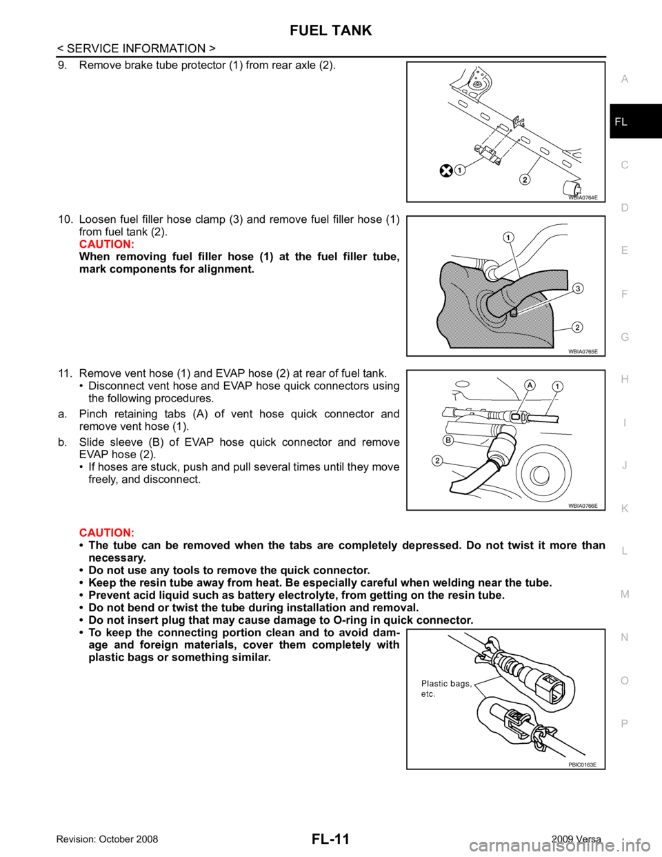
9. Remove brake tube protector (1) from rear axle (2).
10. Loosen fuel filler hose clamp (3) and remove fuel filler hose (1) from fuel tank (2).
CAUTION:
When removing fuel filler hose (1) at the fuel filler tube,
mark components for alignment.
11. Remove vent hose (1) and EVAP hose (2) at rear of fuel tank. • Disconnect vent hose and EVAP hose quick connectors usingthe following procedures.
a. Pinch retaining tabs (A) of vent hose quick connector and remove vent hose (1).
b. Slide sleeve (B) of EVAP hose quick connector and remove EVAP hose (2).
• If hoses are stuck, push and pull several times until they move freely, and disconnect.
CAUTION:
• The tube can be removed when the tabs are completely depressed. Do not twist it more than
necessary.
• Do not use any tools to remove the quick connector.
• Keep the resin tube away from heat. Be especi ally careful when welding near the tube.
• Prevent acid liquid such as battery elect rolyte, from getting on the resin tube.
• Do not bend or twist the tube during installation and removal.
• Do not insert plug that may cause dama ge to O-ring in quick connector.
• To keep the connecting portio n clean and to avoid dam-
age and foreign materials, cover them completely with
plastic bags or something similar. WBIA0765E
WBIA0766E
Page 3652 of 4331
OK >> Replace IPDM E/R. Refer to
PG-27, " Removal and
Installation of IPDM E/R " .
NG >> Repair harness or connector.
Aiming Adjustment INFOID:0000000004306569
The front fog lamp is a semi-sealed beam type which uses a replaceable halogen bulb. Before performing
aiming adjustment, make sure of the following.
• Keep all tires inflated to correct pressure.
• Place vehicle on level surface.
• Set that there is no-load in vehicle other than the driv er (or equivalent weight placed in driver’s position).
Coolant, engine oil filled up to correct level and full fuel tank, spare tire, jack and tools are properly stowed.
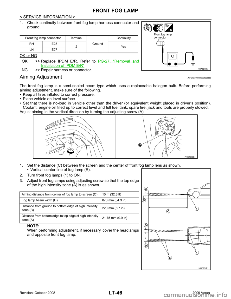
Adjust aiming in the vertical direct ion by turning the adjusting screw (A).
1. Set the distance (C) between the screen and the center of front fog lamp lens as shown. • Vertical center line of fog lamp (E).
2. Turn front fog lamps (1) to ON.
3. Adjust front fog lamps using adjusting screw so that the top edge of the high intensity zone (A) is as shown.
NOTE:
When performing adjustment, if necessary, cover the headlamps
and opposite front fog lamp.
Front fog lamp connector Terminal
Ground Continuity
RH E28 2 Yes
LH E27
Page 3768 of 4331
ENGINE MAINTENANCE (HR16DE)
MA-25
< SERVICE INFORMATION >
C
D E
F
G H
I
J
K
M A
B MA
N
O P
•
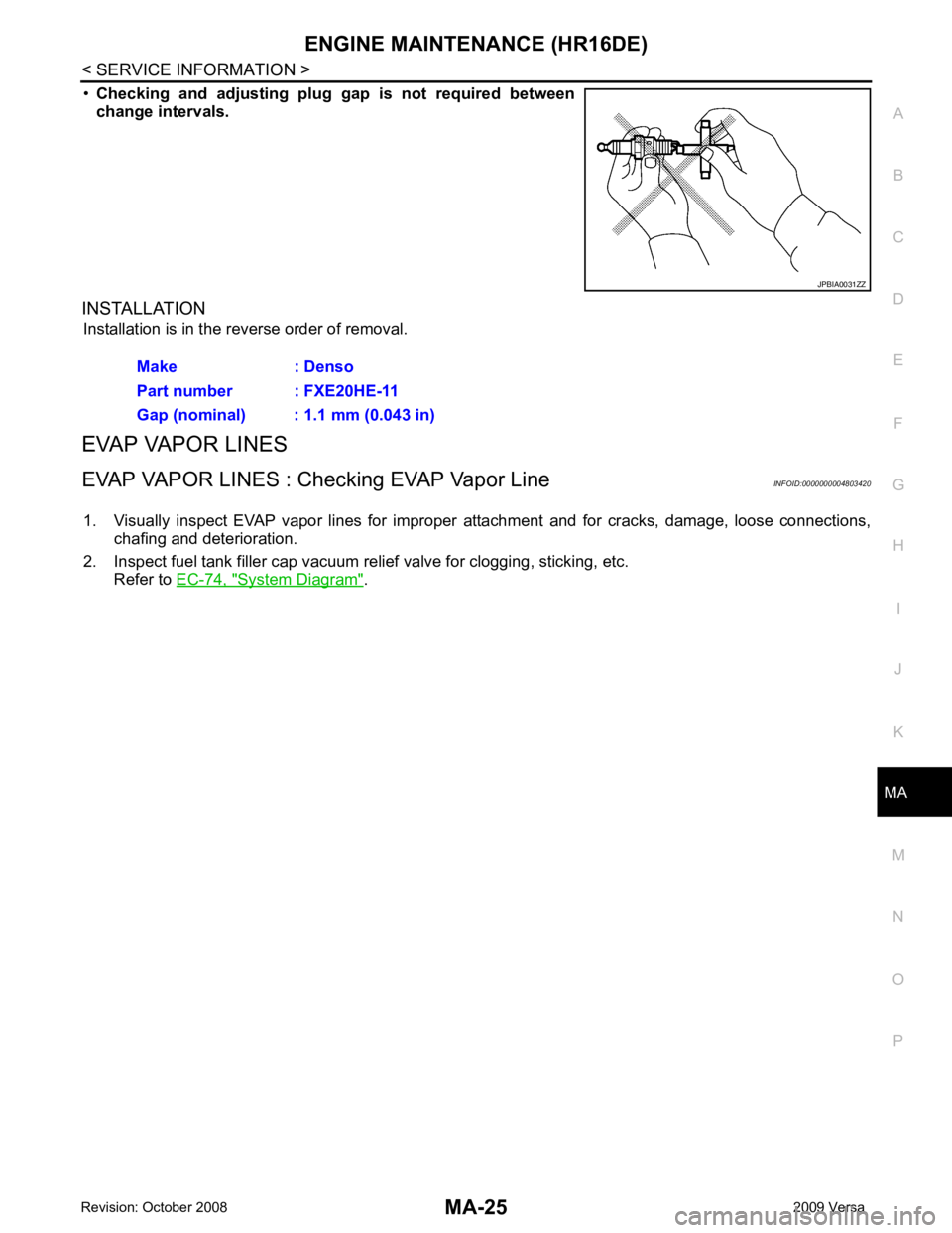
Checking and adjusting plug gap is not required between
change intervals.
INSTALLATION Installation is in the reverse order of removal.
EVAP VAPOR LINES
EVAP VAPOR LINES : Checking EVAP Vapor Line INFOID:0000000004803420
1. Visually inspect EVAP vapor lines for improper attachment and for cracks, damage, loose connections,
chafing and deterioration.
2. Inspect fuel tank filler cap vacuum relief valve for clogging, sticking, etc.
Refer to EC-74, " System Diagram " . JPBIA0031ZZ
Make : Denso
Part number : FXE20HE-11
Gap (nominal) : 1.1 mm (0.043 in)
Page:
< prev 1-8 9-16 17-24