2009 NISSAN LATIO bulb
[x] Cancel search: bulbPage 2425 of 4331
![NISSAN LATIO 2009 Service Repair Manual ON BOARD DIAGNOSTIC (OBD) SYSTEM
EC-1069
< SERVICE INFOMATION >
[MR TYPE 2] C
D E
F
G H
I
J
K L
M A EC
NP
O
4. Touch "ERASE". (The DTC in the ECM will be erased.)
With GST
NOTE:
If the ignition switc NISSAN LATIO 2009 Service Repair Manual ON BOARD DIAGNOSTIC (OBD) SYSTEM
EC-1069
< SERVICE INFOMATION >
[MR TYPE 2] C
D E
F
G H
I
J
K L
M A EC
NP
O
4. Touch "ERASE". (The DTC in the ECM will be erased.)
With GST
NOTE:
If the ignition switc](/manual-img/5/57359/w960_57359-2424.png)
ON BOARD DIAGNOSTIC (OBD) SYSTEM
EC-1069
< SERVICE INFOMATION >
[MR TYPE 2] C
D E
F
G H
I
J
K L
M A EC
NP
O
4. Touch "ERASE". (The DTC in the ECM will be erased.)
With GST
NOTE:
If the ignition switch stays ON after repair work, be sure to turn ignition switch OFF once. Wait at least 10 sec-
onds and then turn it ON (engine stopped) again.
1. Select Service $04 with GST.
No Tools
NOTE:
If the ignition switch stays ON after repair work, be sure to turn ignition switch OFF once. Wait at least 10 sec-
onds and then turn it ON (engine stopped) again.
1. Erase DTC in ECM. Refer to How to Erase Diagnostic Test Mode II (Self-diagnostic Results).
• If the battery is disconnected, the emission-relate d diagnostic information will be lost within 24
hours.
• The following data are cleared when the ECM memory is erased.
- Diagnostic trouble codes
- 1st trip diagnostic trouble codes
- Freeze frame data
- 1st trip freeze frame data
- System readiness test (SRT) codes
- Test values
Malfunction Indicator Lamp (MIL) INFOID:0000000004499927
DESCRIPTION The MIL is located on the instrument panel.
1. The MIL will light up when the ignition switch is turned ON with- out the engine running. This is a bulb check.
If the MIL does not light up, refer to DI-20 or see
EC-1532 .
2. When the engine is start ed, the MIL should go off.
If the MIL remains on, the on board diagnostic system has
detected an engine system malfunction.
ON BOARD DIAGNOSTIC SYSTEM FUNCTION The on board diagnostic system has the following three functions. SEF217U
Page 2426 of 4331
Emission-
related Diagnostic Information " .
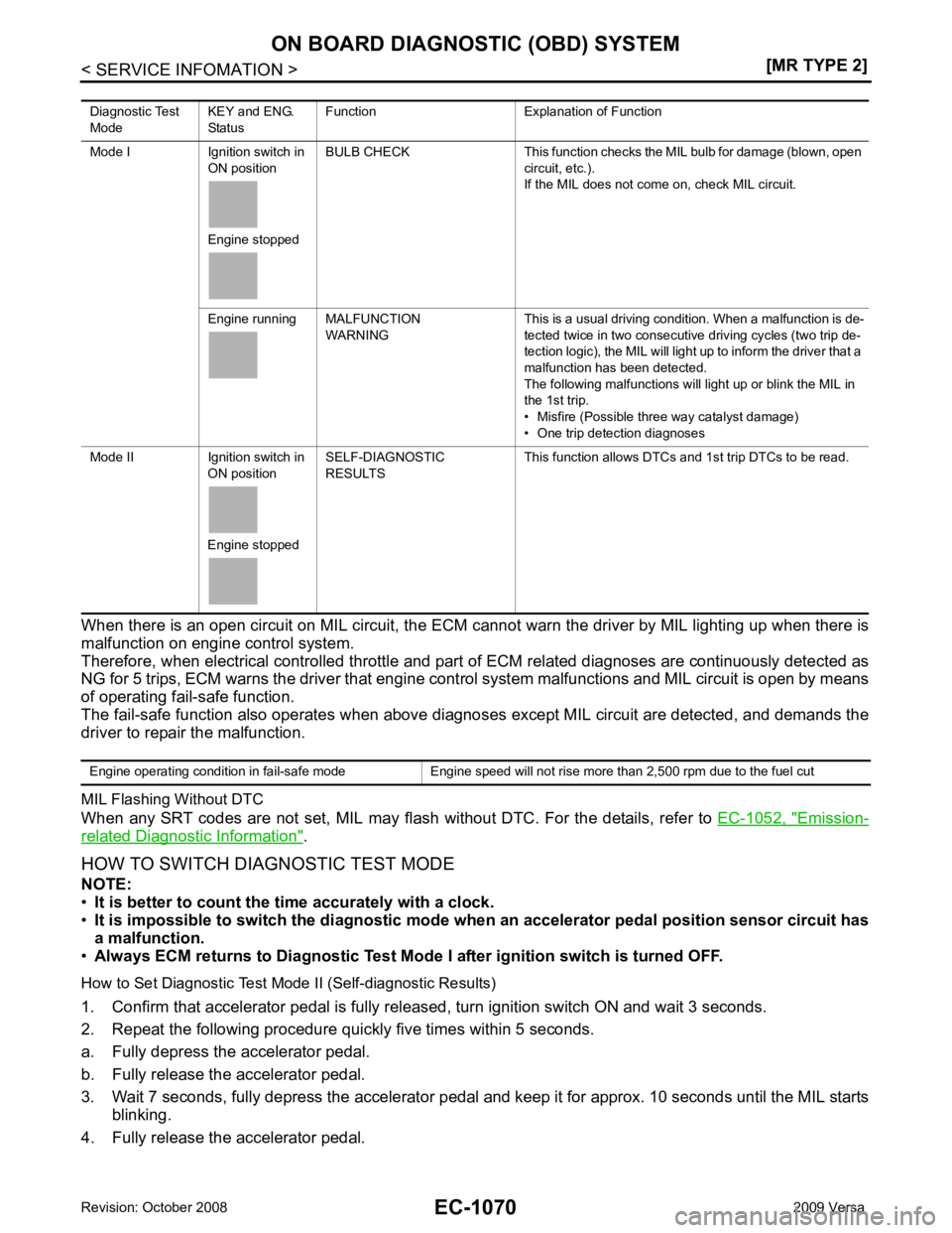
HOW TO SWITCH DIAGNOSTIC TEST MODE
NOTE:
• It is better to count the ti me accurately with a clock.
• It is impossible to switch the di agnostic mode when an accelerator pedal position sensor circuit has
a malfunction.
• Always ECM returns to Diagnostic Test Mode I after ignition switch is turned OFF.
How to Set Diagnostic Test Mode II (Self-diagnostic Results)
1. Confirm that accelerator pedal is fully releas ed, turn ignition switch ON and wait 3 seconds.
2. Repeat the following procedure quickly five times within 5 seconds.
a. Fully depress the accelerator pedal.
b. Fully release the accelerator pedal.
3. Wait 7 seconds, fully depress the accelerator pedal and keep it for approx. 10 seconds until the MIL starts blinking.
4. Fully release the accelerator pedal. Diagnostic Test
Mode KEY and ENG.
Status Function Explanation of Function
Mode I Ignition switch in ON position
Engine stopped BULB CHECK This function checks the MIL bulb for damage (blown, open
circuit, etc.).
If the MIL does not come on, check MIL circuit.
Engine running MALFUNCTION WARNING This is a usual driving condition. When a malfunction is de-
tected twice in two consecutive driving cycles (two trip de-
tection logic), the MIL will light up to inform the driver that a
malfunction has been detected.
The following malfunctions will light up or blink the MIL in
the 1st trip.
• Misfire (Possible three way catalyst damage)
• One trip detection diagnoses
Mode II Ignition switch in ON position
Engine stopped SELF-DIAGNOSTIC
RESULTS This function allows DTCs an
d 1st trip DTCs to be read.
Page 2427 of 4331
![NISSAN LATIO 2009 Service Repair Manual ON BOARD DIAGNOSTIC (OBD) SYSTEM
EC-1071
< SERVICE INFOMATION >
[MR TYPE 2] C
D E
F
G H
I
J
K L
M A EC
NP
O
ECM has entered to Diagnostic Test Mode II (Self-diagnostic results).
How to Erase Diagnosti NISSAN LATIO 2009 Service Repair Manual ON BOARD DIAGNOSTIC (OBD) SYSTEM
EC-1071
< SERVICE INFOMATION >
[MR TYPE 2] C
D E
F
G H
I
J
K L
M A EC
NP
O
ECM has entered to Diagnostic Test Mode II (Self-diagnostic results).
How to Erase Diagnosti](/manual-img/5/57359/w960_57359-2426.png)
ON BOARD DIAGNOSTIC (OBD) SYSTEM
EC-1071
< SERVICE INFOMATION >
[MR TYPE 2] C
D E
F
G H
I
J
K L
M A EC
NP
O
ECM has entered to Diagnostic Test Mode II (Self-diagnostic results).
How to Erase Diagnostic Test Mode II (Self-diagnostic Results) 1. Set ECM in Diagnostic Test Mode II (Self-diagnostic results). Refer to "How to Set Diagnostic Test Mode II (Self-diagnostic Results)".
2. Fully depress the accelerator pedal and keep it for more than 10 seconds. The emission-related diagnostic information has been erased from the backup memory in the ECM.
3. Fully release the accelerator pedal, and confirm the DTC 0000 is displayed.
DIAGNOSTIC TEST MODE I — BULB CHECK In this mode, the MIL on the instrument panel shoul d stay ON. If it remains OFF, check the bulb.
Refer to DI-20 or
EC-1532 .
DIAGNOSTIC TEST MODE I — MALFUNCTION WARNING
These DTC numbers are clarified in Diagnostic Test Mode II (SELF-DIAGNOSTIC RESULTS)
DIAGNOSTIC TEST MODE II — SELF-DIAGNOSTIC RESULTS In this mode, the DTC and 1st trip DTC are indicated by the number of blinks of the MIL as shown below.
The DTC and 1st trip DTC are displayed at the same time. If the MIL does not illuminate in diagnostic test
mode I (Malfunction warning), all displa yed items are 1st trip DTCs. If only one code is displayed when the MIL
illuminates in diagnostic test mode II (SELF-DIAGNOSTIC RESULTS), it is a DTC; if two or more codes are
displayed, they may be either DTCs or 1st trip DTCs. DTC No. is same as that of 1st trip DTC. These uniden- PBIB0092E
MIL Condition
ON When the malfunction is detected.
OFF No malfunction
Page 3284 of 4331
GI
N
O P
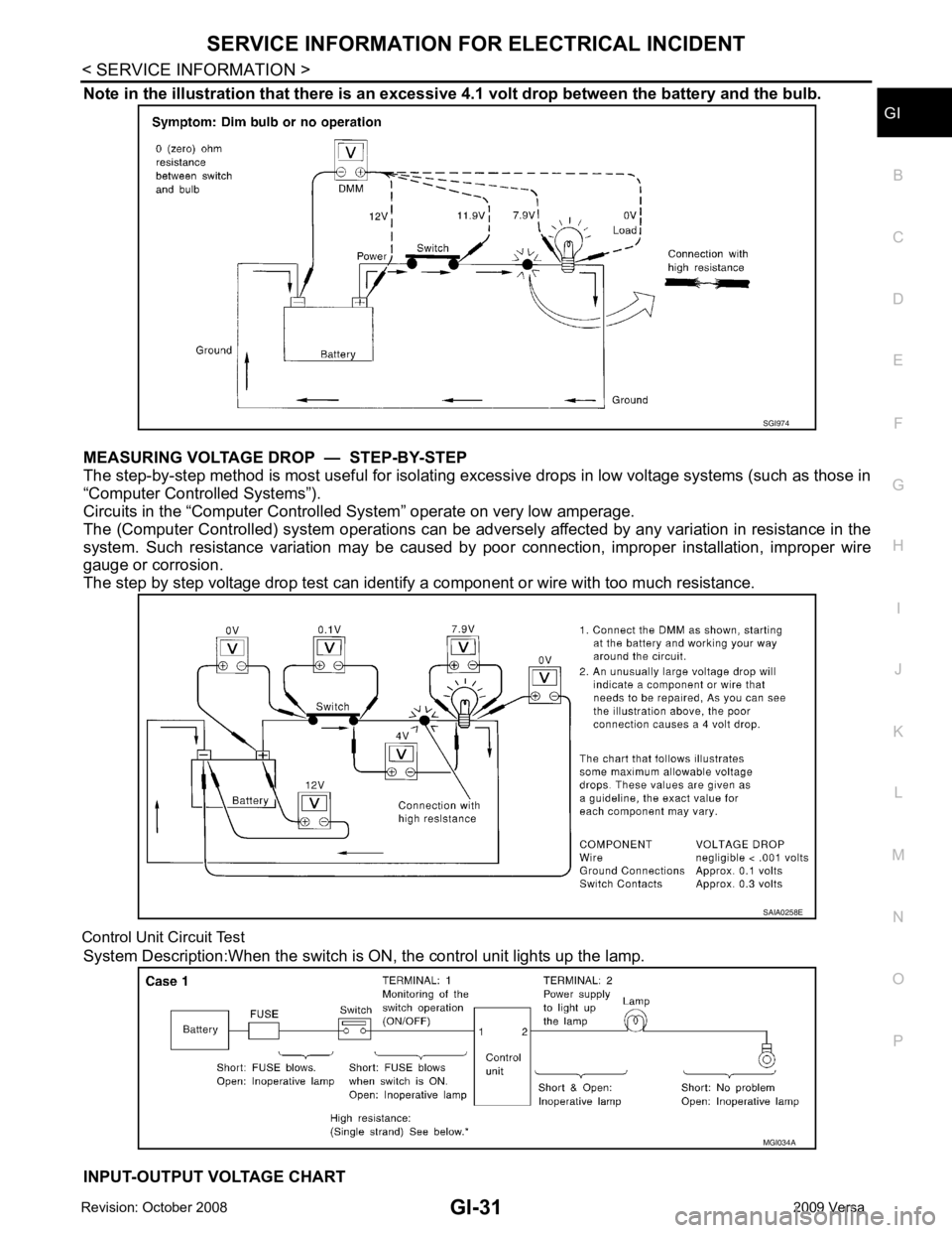
Note in the illustration that there is an excessi
ve 4.1 volt drop between the battery and the bulb.
MEASURING VOLTAGE DRO P — STEP-BY-STEP
The step-by-step method is most useful for isolating excessive drops in low voltage systems (such as those in
“Computer Controlled Systems”).
Circuits in the “Computer Controlled System” operate on very low amperage.
The (Computer Controlled) system oper ations can be adversely affected by any variation in resistance in the
system. Such resistance variation may be caused by poor connection, improper installation, improper wire
gauge or corrosion.
The step by step voltage drop test can identify a component or wire with too much resistance.
Control Unit Circuit Test System Description:When the switch is ON, the control unit lights up the lamp.
INPUT-OUTPUT VOLTAGE CHART
Page 3607 of 4331

LT
N
O P
CONTENTS
LIGHTING SYSTEM
SERVICE INFORMATION .. ..........................3
PRECAUTIONS .............................................. .....3
Precaution for Supplemental Restraint System
(SRS) "AIR BAG" and "SEAT BELT PRE-TEN-
SIONER" ............................................................. ......
3
Precaution Necessary fo r Steering Wheel Rota-
tion After Battery Disconnect ............................... ......
3
HEADLAMP (FOR USA) ................................ .....4
Component Parts and Harness Connector Loca-
tion ...................................................................... ......
4
System Description ............................................. ......4
CAN COMMUNICATION SYSTEM DESCRIP-
TION .................................................................... ......
5
Schematic ........................................................... ......6
Wiring Diagram ................................................... ......7
Terminal and Reference Value for BCM ............. ....10
Terminal and Reference Value for IPDM E/R ..... ....10
How to Perform Trouble Diagnosis ..................... ....11
Preliminary Check ............................................... ....11
CONSULT-III Function (BCM) ............................. ....11
CONSULT-III Function (IPDM E/R) ..................... ....12
Headlamp High Beam Does Not Illuminate (Both
Sides) .................................................................. ....
13
Headlamp High Beam Does Not Illuminate (One
Side) .................................................................... ....
15
High Beam Indicator Lamp Does Not Illuminate .....16
Headlamp Low Beam Does Not Illuminate (Both
Sides) .................................................................. ....
16
Headlamp Low Beam Does Not Illuminate (One
Side) .................................................................... ....
19
Headlamps Do Not Turn OFF ............................. ....20
Aiming Adjustment .............................................. ....21
Bulb Replacement ........ ...........................................22
Removal and Installation .........................................23
Disassembly and Assembly ................................ ....23
HEADLAMP (FOR CANADA) - DAYTIME
LIGHT SYSTEM - ........................................... ....25 Component Parts and Harness Connector Loca-
tion ....................................................................... ....
25
Page 3620 of 4331
OK >> GO TO 3.
NG >> GO TO 4. OK >> Replace IPDM E/R. Refer to
PG-27, " Removal and Installation of IPDM E/R " .
NG >> Replace BCM. Refer to BCS-18, " Removal and Installation of BCM " .
OK >> GO TO 5.
NG >> Repair harness. OK >> GO TO 6.
NG >> Replace headlamp bulb. LT-22, " Bulb Replacement " .
Auto Active Test " .
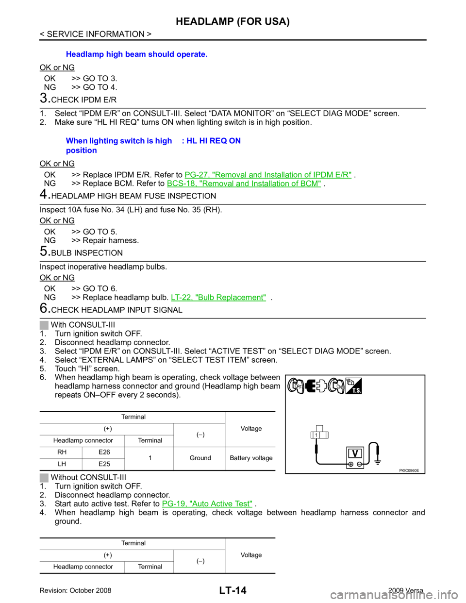
4. When headlamp high beam is operating, check voltage between headlamp harness connector and ground.Headlamp high beam should operate.
When lighting switch is high
position : HL HI REQ ON
Terminal Voltage
(+)
(− )
Headlamp connector Terminal
RH E26 1 Ground Battery voltage
LH E25
Terminal Voltage
(+)
(− )
Headlamp connector Terminal
Page 3621 of 4331
LT
N
O P
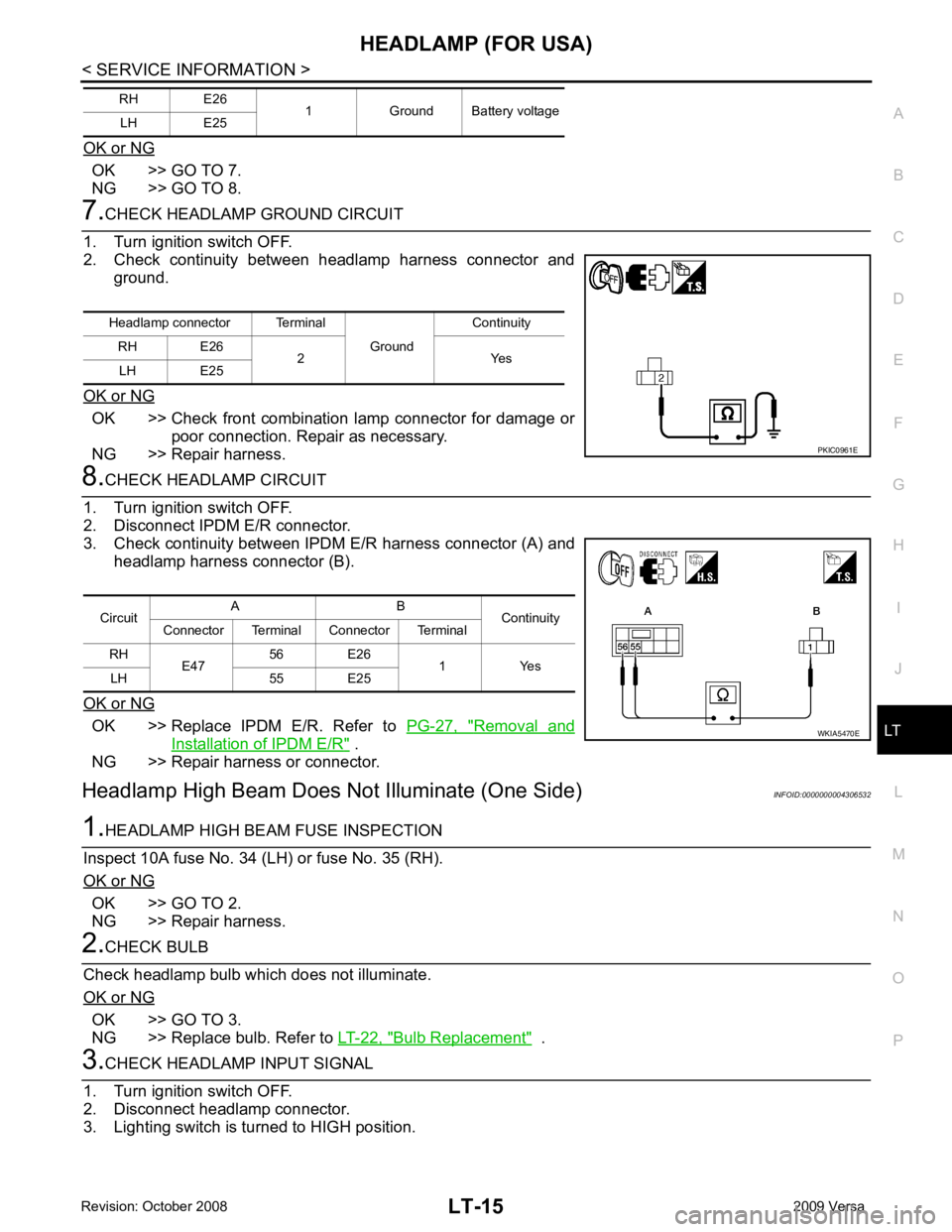
OK or NG OK >> GO TO 7.
NG >> GO TO 8. OK >> Check front combination lamp connector for damage or
poor connection. Repair as necessary.
NG >> Repair harness. OK >> Replace IPDM E/R. Refer to
PG-27, " Removal and
Installation of IPDM E/R " .
NG >> Repair harness or connector.
Headlamp High Beam Does No t Illuminate (One Side) INFOID:0000000004306532OK >> GO TO 2.
NG >> Repair harness. OK >> GO TO 3.
NG >> Replace bulb. Refer to LT-22, " Bulb Replacement " .Headlamp connector Terminal
Ground Continuity
RH E26 2 Yes
LH E25
Page 3622 of 4331
LT-16< SERVICE INFORMATION >
HEADLAMP (FOR USA)
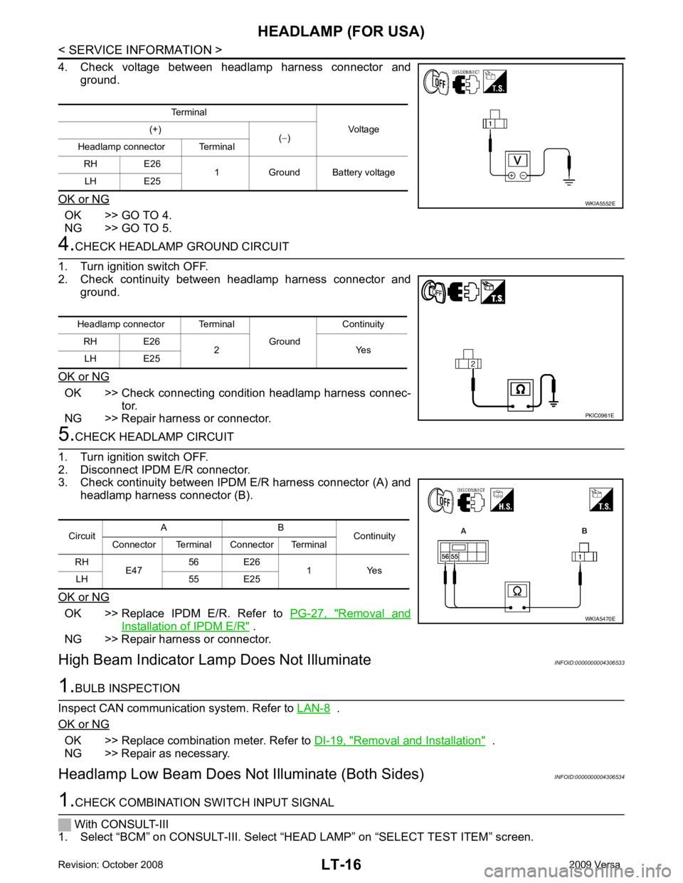
4. Check voltage between headlamp harness connector and ground.
OK or NG OK >> GO TO 4.
NG >> GO TO 5. 4.
CHECK HEADLAMP GROUND CIRCUIT
1. Turn ignition switch OFF.
2. Check continuity between headlamp harness connector and ground.
OK or NG OK >> Check connecting condition headlamp harness connec-
tor.
NG >> Repair harness or connector. 5.
CHECK HEADLAMP CIRCUIT
1. Turn ignition switch OFF.
2. Disconnect IPDM E/R connector.
3. Check continuity between IPDM E/R harness connector (A) and
headlamp harness connector (B).
OK or NG OK >> Replace IPDM E/R. Refer to
PG-27, " Removal and
Installation of IPDM E/R " .
NG >> Repair harness or connector.
High Beam Indicator Lam p Does Not Illuminate INFOID:00000000043065331.
BULB INSPECTION
Inspect CAN communication system. Refer to LAN-8 .
OK or NG OK >> Replace combination meter. Refer to
DI-19, " Removal and Installation " .
NG >> Repair as necessary.
Headlamp Low Beam Does Not Illuminate (Both Sides) INFOID:00000000043065341.
CHECK COMBINATION SWITCH INPUT SIGNAL
With CONSULT-III
1. Select “BCM” on CONSULT-III. Select “HEAD LAMP” on “SELECT TEST ITEM” screen.
Terminal
Voltage
(+)
(− )
Headlamp connector Terminal
RH E26 1 Ground Battery voltage
LH E25 WKIA5552E
Headlamp connector Terminal
Ground Continuity
RH E26 2 Yes
LH E25 PKIC0961E
Circuit
A B
Continuity
Connector Terminal Connector Terminal
RH E47 56 E26
1 Yes
LH 55 E25 WKIA5470E