2009 NISSAN LATIO ESP
[x] Cancel search: ESPPage 3000 of 4331
EM
NP
O
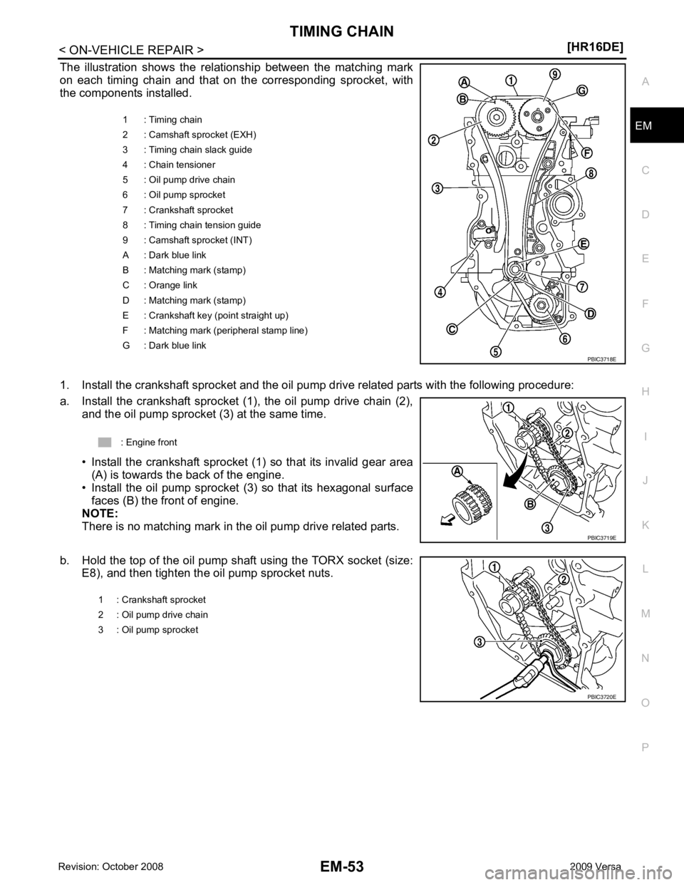
The illustration shows the relationship between the matching mark
on each timing chain and that on the corresponding sprocket, with
the components installed.
1. Install the crankshaft sprocket and the oil pump drive related parts with the following procedure:
a. Install the crankshaft sprocket (1), the oil pump drive chain (2), and the oil pump sprocket (3) at the same time.
• Install the crankshaft sprocket (1) so that its invalid gear area (A) is towards the back of the engine.
• Install the oil pump sprocket (3) so that its hexagonal surface
faces (B) the front of engine.
NOTE:
There is no matching mark in the oil pump drive related parts.
b. Hold the top of the oil pump shaft using the TORX socket (size: E8), and then tighten the oil pump sprocket nuts. 1 : Timing chain
2 : Camshaft sprocket (EXH)
3 : Timing chain slack guide
4 : Chain tensioner
5 : Oil pump drive chain
6 : Oil pump sprocket
7 : Crankshaft sprocket
8 : Timing chain tension guide
9 : Camshaft sprocket (INT)
A : Dark blue link
B : Matching mark (stamp)
C : Orange link
D : Matching mark (stamp)
E : Crankshaft key (point straight up)
F : Matching mark (peripheral stamp line)
G : Dark blue link
Page 3021 of 4331
Fluids and Lubricants " .
• Use procedure below to check for fuel leakage.
- Turn ignition switch “ON” (with engine stopped). With fuel pressure applied to fuel piping, check for fuel leak-
age at connection points.
- Start engine. With engine speed increased, che ck again for fuel leakage at connection points.
• Run engine to check for unusual noise and vibration. NOTE:
If hydraulic pressure inside timing chain tensioner drops after removal/installation, slack in the guide may
generate a pounding noise during and just after engine start. However, this is normal. Noise will stop after
hydraulic pressure rises.
• Warm up engine thoroughly to make sure there is no leakage of fuel, or any oil/fluids including engine oil and
engine coolant.
• Bleed air from lines and hoses of applicable lines, such as in cooling system.
• After cooling down engine, again check oil/fluid levels including engine oil and engine coolant. Refill to the
specified level, if necessary.
Summary of the inspection items:
*: Transmission/transaxle/CVT fluid, power steering fluid, brake fluid, etc.
Inspection of Camshaft Sprocket (INT) Oil Groove
CAUTION:
• Perform this inspection only when DTC P0011 is de tected in self-diagnostic results of CONSULT-III
and it is directed according to inspect ion procedure of EC section. Refer to EC-133, " Diagnosis Pro-
cedure " .
• Check when engine is cold so as to pr event burns from the splashing engine oil.
1. Check engine oil level. Refer to LU-7, " Inspection " .
2. Perform the following procedure so as to prevent the engine from being unintentionally started while
checking.
a. Release the fuel pressure. Refer to EC-498, " Inspection " .
b. Remove intake manifold. Refer to EM-28, " Exploded View " .
c. Disconnect ignition coil and injector harness connectors. Refer to EM-46, " Exploded View " .
3. Remove intake valve timing control solenoid valve. Refer to EM-49, " Exploded View " .
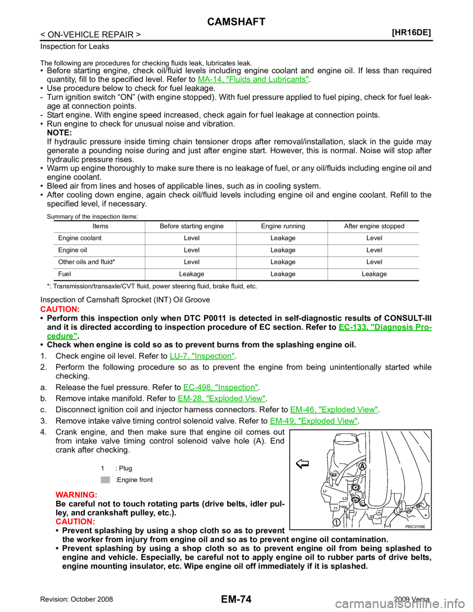
4. Crank engine, and then make sure that engine oil comes out from intake valve timing control solenoid valve hole (A). End
crank after checking.
WARNING:
Be careful not to touch rotating parts (drive belts, idler pul-
ley, and crankshaft pulley, etc.).
CAUTION:
• Prevent splashing by using a shop cloth so as to prevent
the worker from injury from engine oil an d so as to prevent engine oil contamination.
• Prevent splashing by using a shop cloth so as to prevent engine oil from being splashed to
engine and vehicle. Especially, be careful not to apply engine oil to rubber parts of drive belts,
engine mounting insulator, etc. Wipe engi ne oil off immediately if it is splashed.
Items Before starting engine Engine running After engine stopped
Engine coolant Level Leakage Level
Engine oil Level Leakage Level
Other oils and fluid* Level Leakage Level
Fuel Leakage Leakage Leakage 1 : Plug
:Engine front
Page 3043 of 4331
Removal and Installation " .
2. Remove knock sensor. CAUTION:
Carefully handle knock sensor avoiding shocks.
3. Remove crankshaft position sensor (POS) and cover. CAUTION:
• Avoid impacts such as a dropping.
• Never disassemble.
• Keep it away from metal particles.
• Never place the sensor where it is exposed to magnetism.
4. Remove piston and connecting rod assembly with the following procedure: • Before removing piston and connecting rod assembly, check the connecting rod side clearance. Refer to
EM-103, " Inspection " .
a. Position crankshaft pin corresponding to connecting rod to be removed onto the bottom dead center.
b. Remove connecting rod cap.
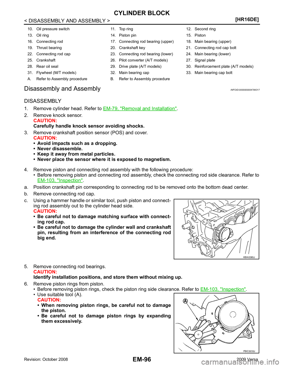
c. Using a hammer handle or similar tool, push piston and connect- ing rod assembly out to the cylinder head side.
CAUTION:
• Be careful not to damage matching surface with connect-
ing rod cap.
• Be careful not to damage the cylinder wall and crankshaft pin, resulting from an inte rference of the connecting rod
big end.
5. Remove connecting rod bearings. CAUTION:
Identify installation positions, and store them without mixing up.
6. Remove piston rings from piston. • Before removing piston rings, check the piston ring side clearance. Refer to EM-103, " Inspection " .
• Use suitable tool (A).
CAUTION:
• When removing piston rings, be careful not to damage the piston.
• Be careful not to damage piston rings by expanding
them excessively.
10. Oil pressure switch 11. Top ring 12. Second ring
13. Oil ring 14. Piston pin 15. Piston
16. Connecting rod 17. Connecting rod bearing (upper) 18. Main bearing (upper)
19. Thrust bearing 20. Crankshaft key 21. Connecting rod cap bolt
22. Connecting rod cap 23. Connecting rod bearing (lower) 24. Main bearing (lower)
25. Crankshaft 26. Pilot converter (A/T models) 27. Signal plate
28. Rear oil seal 29. Drive plate (A/T models) 30. Reinforcement plate (A/T models)
31. Flywheel (M/T models) 32. Main bearing cap 33. Main bearing cap bolt
A. Refer to Assembly procedure B. Refer to Assembly procedure PBIC3233J
Page 3060 of 4331
![NISSAN LATIO 2009 Service Repair Manual HOW TO SELECT PISTON AND BEARING
EM-113
< DISASSEMBLY AND ASSEMBLY >
[HR16DE] C
D E
F
G H
I
J
K L
M A EM
NP
O
In grinding crankshaft pin to
use undersize bearings, keep the
fillet R (A) [0.8 NISSAN LATIO 2009 Service Repair Manual HOW TO SELECT PISTON AND BEARING
EM-113
< DISASSEMBLY AND ASSEMBLY >
[HR16DE] C
D E
F
G H
I
J
K L
M A EM
NP
O
In grinding crankshaft pin to
use undersize bearings, keep the
fillet R (A) [0.8](/manual-img/5/57359/w960_57359-3059.png)
HOW TO SELECT PISTON AND BEARING
EM-113
< DISASSEMBLY AND ASSEMBLY >
[HR16DE] C
D E
F
G H
I
J
K L
M A EM
NP
O
In grinding crankshaft pin to
use undersize bearings, keep the
fillet R (A) [0.8 - 1.2 mm (0.031 - 0.047 in)].
Main Bearing INFOID:0000000004784321
HOW TO SELECT MAIN BEARING
When New Cylinder Block and Crankshaft Are Used
1. “Main Bearing Selection Table” rows correspond to main bearing housing grade on left side of cylinder block.
• If there is a corrected stamp mark (B) on cylinder block, use it as a correct reference.
2. Apply main journal diameter grade stamped on crankshaft front side to column in the “Main Bearing Selection Table”.
3. Read the symbol at the cross point of selected row and column in the “Main Bearing Selection Table”.
4. Apply the symbol obtained to the “Main B earing Grade Table” to select main bearing.
NOTE:
Service part is available as a set of both upper and lower.
When Cylinder Block and Crankshaft Are Reused 1. Measure the dimensions of the cylinder block ma in bearing housing inner diameter and crankshaft main
journal diameter individually. Refer to EM-103, " Inspection " .
2. Apply the measured dimension to t he “Main Bearing Selection Table”.
3. Read the symbol at the cross point of selected row and column in the “Main Bearing Selection Table”.
4. Apply the symbol obtained to the “Main B earing Grade Table” to select main bearing.
Bearing undersize table:
Refer to EM-124, " Connecting Rod Bearing " .
PBIC3263J
A : Basic stamp mark
: Engine front PBIC3760E
A : Main journal diameter grade (No. 1 to 5 from left)
B : Crankshaft pin journal diameter grade (No. 1 to 4 from left) PBIC3757E
Page 3104 of 4331
EM
NP
O
3. Disconnect fuel feed hose from hose clamp.
NOTE:
There is no fuel return path.
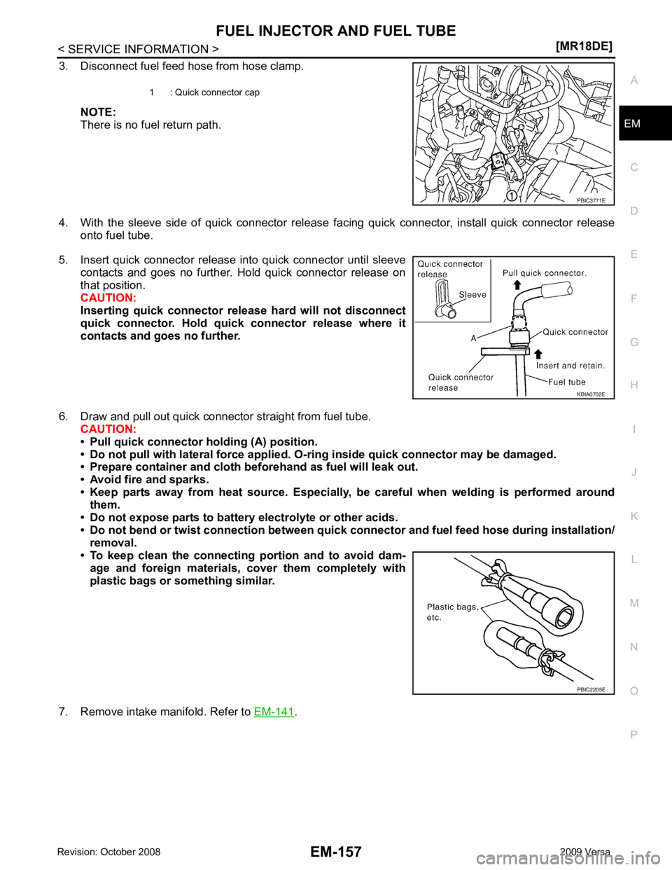
4. With the sleeve side of quick connector release facing quick connector, install quick connector release onto fuel tube.
5. Insert quick connector release into quick connector until sleeve contacts and goes no further. Hold quick connector release on
that position.
CAUTION:
Inserting quick connector re lease hard will not disconnect
quick connector. Hold qui ck connector release where it
contacts and goes no further.
6. Draw and pull out quick connector straight from fuel tube. CAUTION:
• Pull quick connector holding (A) position.
• Do not pull with lateral force applied. O-ring inside quick connector may be damaged.
• Prepare container and cloth be forehand as fuel will leak out.
• Avoid fire and sparks.
• Keep parts away from heat source. Especially, be careful when welding is performed around
them.
• Do not expose parts to battery electrolyte or other acids.
• Do not bend or twist connection between quick co nnector and fuel feed hose during installation/
removal.
• To keep clean the connecting portion and to avoid dam-
age and foreign materials, cover them completely with
plastic bags or something similar.
7. Remove intake manifold. Refer to EM-141 .
1 : Quick connector cap
KBIA0702E
PBIC2205E
Page 3112 of 4331
EM
NP
O
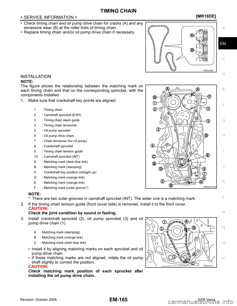
• Check timing chain and oil pump drive chain for cracks (A) and any
excessive wear (B) at the roller links of timing chain.
• Replace timing chain and/or oil pump drive chain if necessary.
INSTALLATION NOTE:
The figure shows the relationship between the matching mark on
each timing chain and that on the corresponding sprocket, with the
components installed.
1. Make sure that crankshaft key points are aligned.
NOTE:
*: There are two outer grooves in camshaft spro cket (INT). The wider one is a matching mark.
2. If the timing chain tension guide (front cover si de) is removed, install it to the front cover.
CAUTION:
Check the joint condition by sound or feeling.
3. Install crankshaft sprocket (2), oil pump sprocket (3) and oil pump drive chain (1).
• Install it by aligning matching marks on each sprocket and oil pump drive chain.
• If these matching marks are not aligned, rotate the oil pump
shaft slightly to correct the position.
CAUTION:
Check matching mark position of each sprocket after
installing the oil pump drive chain. PBIC3171J
Page 3125 of 4331
Component " .
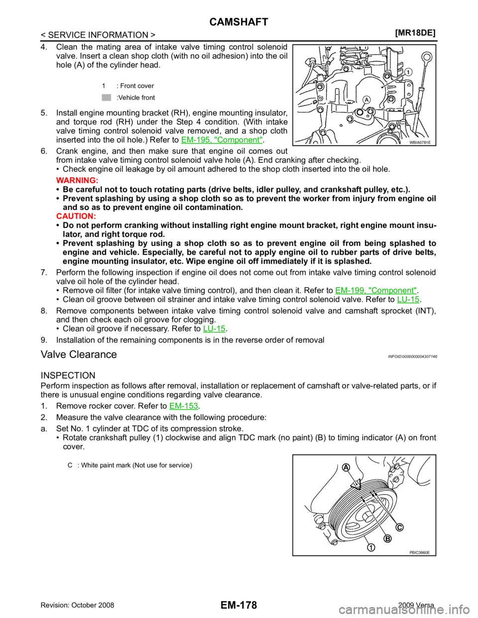
6. Crank engine, and then make sure that engine oil comes out from intake valve timing control solenoid valve hole (A). End cranking after checking.
• Check engine oil leakage by oil amount adhered to the shop cloth inserted into the oil hole.
WARNING:
• Be careful not to touch rotating parts (drive be lts, idler pulley, and crankshaft pulley, etc.).
• Prevent splashing by using a shop cloth so as to prevent the worker from injury from engine oil
and so as to prevent engi ne oil contamination.
CAUTION:
• Do not perform cranking without installing right engine mount bracket, right engine mount insu-
lator, and right torque rod.
• Prevent splashing by using a shop cloth so as to prevent engine oil from being splashed to
engine and vehicle. Especially, be careful not to apply engine oil to rubber parts of drive belts,
engine mounting insulator, etc. Wipe engi ne oil off immediately if it is splashed.
7. Perform the following inspection if engine oil does not come out from intake valve timing control solenoid valve oil hole of the cylinder head.
• Remove oil filter (for intake valve timing control), and then clean it. Refer to EM-199, " Component " .
• Clean oil groove between oil strainer and intake valve timing control solenoid valve. Refer to LU-15 .
8. Remove components between intake valve timing c ontrol solenoid valve and camshaft sprocket (INT),
and then check each oil groove for clogging.
• Clean oil groove if necessary. Refer to LU-15 .
9. Installation of the remaining components is in the reverse order of removal
Valve Clearance INFOID:0000000004307146
INSPECTION
Perform inspection as follows after removal, installation or replacement of camshaft or valve-related parts, or if
there is unusual engine conditions regarding valve clearance.
1. Remove rocker cover. Refer to EM-153 .
2. Measure the valve clearance with the following procedure:
a. Set No. 1 cylinder at TDC of its compression stroke. • Rotate crankshaft pulley (1) clockwise and align TDC mark (no paint) (B) to timing indicator (A) on front
cover. 1 : Front cover
:Vehicle front
Page 3148 of 4331
EM
NP
O
CAUTION:
• Avoid impacts such as a dropping.
• Never disassemble.
• Keep it away from metal particles.
• Never place sensor in a location wher e it is exposed to magnetism.
8. Remove oil filter (for intake valve timing control).
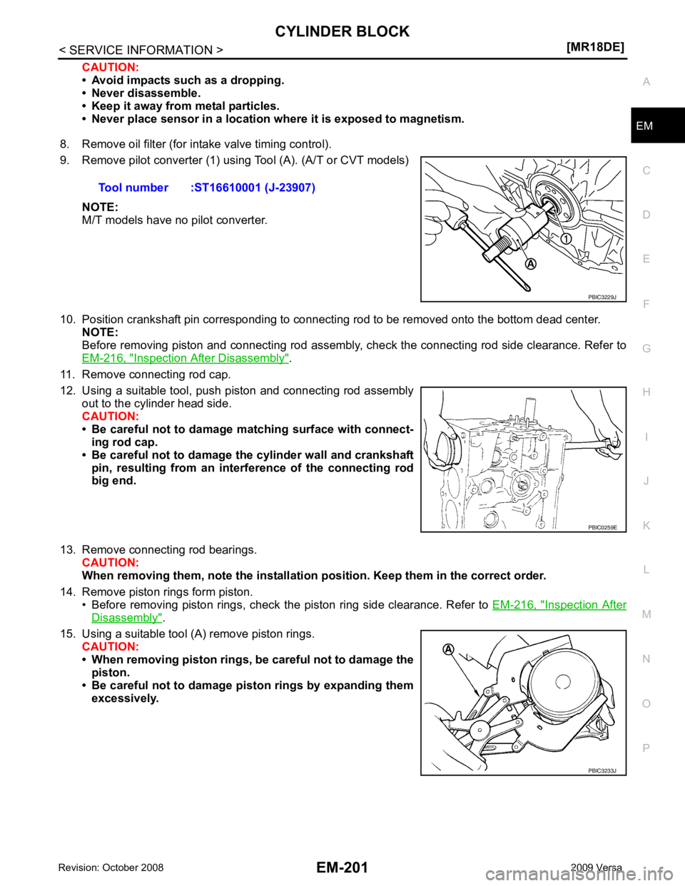
9. Remove pilot converter (1) using Tool (A). (A/T or CVT models)
NOTE:
M/T models have no pilot converter.
10. Position crankshaft pin corresponding to connecting rod to be removed onto the bottom dead center. NOTE:
Before removing piston and connecting rod assembly, check the connecting rod side clearance. Refer to
EM-216, " Inspection After Disassembly " .
11. Remove connecting rod cap.
12. Using a suitable tool, push piston and connecting rod assembly out to the cylinder head side.
CAUTION:
• Be careful not to damage matching surface with connect- ing rod cap.
• Be careful not to damage the cylinder wall and crankshaft pin, resulting from an inte rference of the connecting rod
big end.
13. Remove connecting rod bearings. CAUTION:
When removing them, note the installation position. Keep them in the correct order.
14. Remove piston rings form piston. • Before removing piston rings, check the piston ring side clearance. Refer to EM-216, " Inspection After
Disassembly " .
15. Using a suitable tool (A) remove piston rings. CAUTION:
• When removing piston rings, be careful not to damage the
piston.
• Be careful not to damage piston rings by expanding them excessively.Tool number :ST16610001 (J-23907)
PBIC0259E
PBIC3233J