2009 NISSAN LATIO ECU
[x] Cancel search: ECUPage 1455 of 4331
EC
NP
O
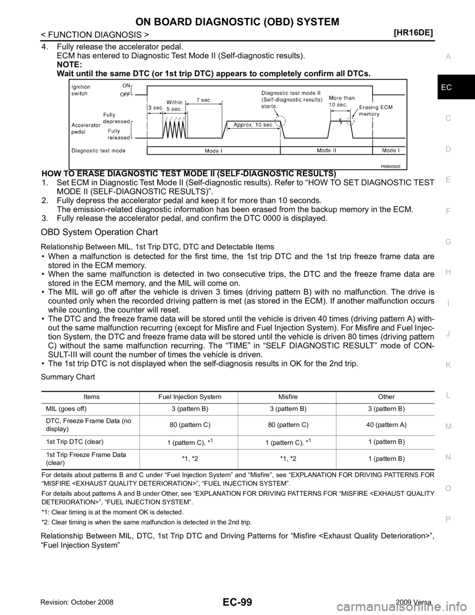
4. Fully release the accelerator pedal.
ECM has entered to Diagnostic Test Mode II (Self-diagnostic results).
NOTE:
Wait until the same DTC (or 1st trip DTC) appears to completely confirm all DTCs.
HOW TO ERASE DIAGNOSTIC TEST MO DE II (SELF-DIAGNOSTIC RESULTS)
1. Set ECM in Diagnostic Test Mode II (Self-diagnostic results). Refer to “HOW TO SET DIAGNOSTIC TEST
MODE II (SELF-DIAGNOSTIC RESULTS)”.
2. Fully depress the accelerator pedal and keep it for more than 10 seconds. The emission-related diagnostic information has been erased from the backup memory in the ECM.
3. Fully release the accelerator pedal, and confirm the DTC 0000 is displayed.
OBD System Operation Chart
Relationship Between MIL, 1st Trip DTC, DTC and Detectable Items
• When a malfunction is detected for the first time, the 1st trip DTC and the 1st trip freeze frame data are
stored in the ECM memory.
• When the same malfunction is detected in two consec utive trips, the DTC and the freeze frame data are
stored in the ECM memory, and the MIL will come on.
• The MIL will go off after the vehicle is driven 3 times (driving pattern B) with no malfunction. The drive is
counted only when the recorded driving pattern is met (as stored in the ECM). If another malfunction occurs
while counting, the counter will reset.
• The DTC and the freeze frame data will be stored until the v ehicle is driven 40 times (driving pattern A) with-
out the same malfunction recurring (except for Misfire and Fuel Injection System). For Misfire and Fuel Injec-
tion System, the DTC and freeze frame data will be stored until the vehicle is driven 80 times (driving pattern
C) without the same malfunction recurring. The “T IME” in “SELF DIAGNOSTIC RESULT” mode of CON-
SULT-III will count the number of times the vehicle is driven.
• The 1st trip DTC is not displayed when the self-diagnosis results in OK for the 2nd trip.
Summary Chart
For details about patterns B an d C under “Fuel Injection System” and “Misfire”, see “EXPLAN ATION FOR DRIVING PATTERNS FOR
“MISFIRE
For details about patterns A and B under Other, see “EXPLANATION FOR DRIVING PATTERNS FOR “MISFIRE
*1: Clear timing is at the moment OK is detected.
*2: Clear timing is when the same malfunction is detected in the 2nd trip.
Relationship Between MIL, DTC, 1st Tr ip DTC and Driving Patterns for “Misfire
“Fuel Injection System”
Page 1461 of 4331
EC
NP
O
*1: This item includes 1st trip DTCs.
*2: This mode includes 1st trip freeze frame data or freeze fr ame data. The items appear on CONSULT-III screen in freeze frame data
mode only if a 1st trip DTC or DTC is detected. For details, refer to EC-90, " Diagnosis Description " .
*3: Always “CMPLT ” is displayed.
WORK SUPPORT MODE
Work Item
*: This function is not necessary in the usual service procedure.
SELF DIAGNOSTIC RESULT MODE
Self Diagnostic Item Regarding items of DTC and 1st trip DTC, refer to EC-475, " DTC Index " .)
Freeze Frame Data and 1st Trip Freeze Frame Data WORK ITEM CONDITION USAGE
FUEL PRESSURE RELEASE • FUEL PUMP WILL STOP BY TOUCHING “START” DUR- ING IDLING.
CRANK A FEW TIMES AFTER ENGINE STALLS. When releasing fuel pressure from
fuel line
IDLE AIR VOL LEARN • THE IDLE AIR VOLUME THAT KEEPS THE ENGINE WITHIN THE SPECIFIED RANGE IS MEMORIZED IN
ECM. When learning the idle air volume
SELF-LEARNING CONT • THE COEFFICI ENT OF SELF-LEARNING CONTROL
MIXTURE RATIO RETURNS TO THE ORIGINAL COEF-
FICIENT. When clearing mixture ratio self-
learning value
EVAP SYSTEM CLOSE CLOSE THE EVAP CANISTER VENT CONTROL VALVE IN ORDER TO MAKE EVAP SYSTEM CLOSE UNDER THE
FOLLOWING CONDITIONS.
• IGN SW ON
• ENGINE NOT RUNNING
• AMBIENT TEMPERATURE IS ABOVE 0 °C (32 °F).
• NO VACUUM AND NO HIGH PRESSURE IN EVAP SYS- TEM
• FUEL TANK TEMP. IS MORE THAN 0 °C (32 °F).
• WITHIN 10 MINUTES AFTER STARTING “EVAP SYS- TEM CLOSE”
• WHEN TRYING TO EXECUTE “EVAP SYSTEM CLOSE”
UNDER THE CONDITION EXCEPT ABOVE, CONSULT-
II WILL DISCONTINUE IT AND DISPLAY APPROPRIATE
INSTRUCTION.
NOTE:
WHEN STARTING ENGINE, CONSULT-III MAY DIS-
PLAY “BATTERY VOLTAGE IS LOW. CHARGE BAT-
TERY”, EVEN IN USING CHARGED BATTERY. When detecting EVAP vapor leak
point of EVAP system
VIN REGISTRATION • IN THIS MODE, VIN IS REGIST ERED IN ECM. When registering VIN in ECM
TARGET IDLE RPM ADJ* • IDLE CONDITION When setting target idle speed
TARGET IGN TIM ADJ* • IDLE CONDITION When adjusting target ignition timingFreeze frame data
item* Description
DIAG TROUBLE
CODE
[PXXXX] • The engine control co
mponent part/control system has a trouble code, it is displayed as PXXXX. (Refer to
EC-475, " DTC Index " .)
FUEL SYS-B1 • “Fuel injection system status” at the moment a malfunction is detected is displayed.
• One mode in the following is displayed. Mode2: Open loop due to detected system malfunction
Mode3: Open loop due to driving conditions (power enrichment, deceleration enleanment)
Mode4: Closed loop - using oxygen sensor(s) as feedback for fuel control
Mode5: Open loop - has not yet satisfied condition to go to closed loop
Page 1476 of 4331
Diagnosis Description " , “DTC AND FREEZE FRAME DATA”, “How to Erase DTC and 1st Trip
DTC”.
>> GO TO 2. Ground Inspection " .
OK or NG OK >> GO TO 3.
NG >> Repair or replace malfunctioning part. How to Perform Efficient Diagnosis for an Electrical Incident " , “INCIDENT SIMULATION
TESTS”.
OK or NG OK >> GO TO 4.
NG >> Repair or replace malfunctioning part. How to Check Terminal " , “HOW TO PROBE CONNECTORS”, “How to Check Enlarged Con-
tact Spring of Terminal”.
OK or NG OK >>
INSPECTION END
NG >> Repair or replace connector. STEP in Work Flow Situation
2 The CONSULT-III is used. The SELF DIAGNOSTIC RESULT screen shows time data other than 0 or [1t].
3 or 4 The symptom described by the customer does not recur. 5 (1st trip) DTC does not appear during the DTC Confirmation Procedure.
10 The Diagnostic Procedure for PXXXX does not indicate the malfunctioning area.
Page 1481 of 4331
EC
NP
O
Refer to
EC-120, " Diagnosis Procedure " .
Is the inspection result normal? YES >> Replace IPDM E/R. Refer to
PG-27, " Removal and Installation of IPDM E/R " .
NO >> Repair open circuit or short to ground or short to power in harness or connectors.
Ground Inspection INFOID:0000000004784172
Ground connections are very important to the proper oper ation of electrical and electronic circuits. Ground
connections are often exposed to moisture, dirt and other corrosive elements. The corrosion (rust) can
become an unwanted resistance. This unwanted re sistance can change the way a circuit works.
Electronically controlled circuits are very sensitive to proper grounding. A loose or corroded ground can drasti-
cally affect an electronically controlled circuit. A poor or corroded ground can easily affect the circuit. Even
when the ground connection looks clean, there can be a thin film of rust on the surface.
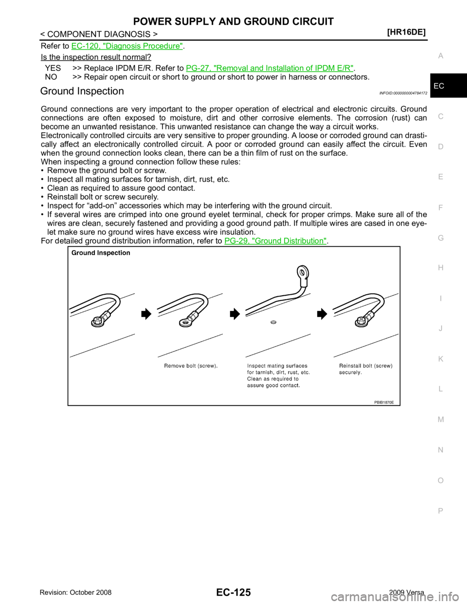
When inspecting a ground connection follow these rules:
• Remove the ground bolt or screw.
• Inspect all mating surfaces for tarnish, dirt, rust, etc.
• Clean as required to assure good contact.
• Reinstall bolt or screw securely.
• Inspect for “add-on” accessories which may be interfering with the ground circuit.
• If several wires are crimped into one ground eyelet terminal, check for proper crimps. Make sure all of the wires are clean, securely fastened and providing a good ground path. If multiple wires are cased in one eye-
let make sure no ground wires have excess wire insulation.
For detailed ground distribution information, refer to PG-29, " Ground Distribution " .
Page 1535 of 4331
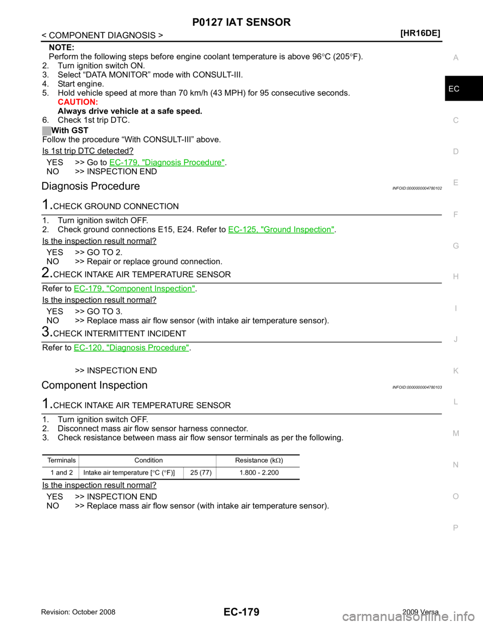
EC
NP
O
NOTE:
Perform the following steps before engine coolant temperature is above 96 °C (205 °F).
2. Turn ignition switch ON.
3. Select “DATA MONITOR” mode with CONSULT-III.
4. Start engine.
5. Hold vehicle speed at more than 70 km/h (43 MPH) for 95 consecutive seconds.
CAUTION:
Always drive vehicle at a safe speed.
6. Check 1st trip DTC.
With GST
Follow the procedure “With CONSULT-III” above.
Is 1st trip DTC detected? YES >> Go to
EC-179, " Diagnosis Procedure " .
NO >> INSPECTION END
Diagnosis Procedure INFOID:0000000004780102Ground Inspection " .
Is the inspection result normal? YES >> GO TO 2.
NO >> Repair or replace ground connection. Component Inspection " .
Is the inspection result normal? YES >> GO TO 3.
NO >> Replace mass air flow sensor ( with intake air temperature sensor).Diagnosis Procedure " .
>> INSPECTION END
Component Inspection INFOID:0000000004780103YES >> INSPECTION END
NO >> Replace mass air flow sensor ( with intake air temperature sensor).
Page 1817 of 4331
EC
NP
O
ECU DIAGNOSIS
ECM
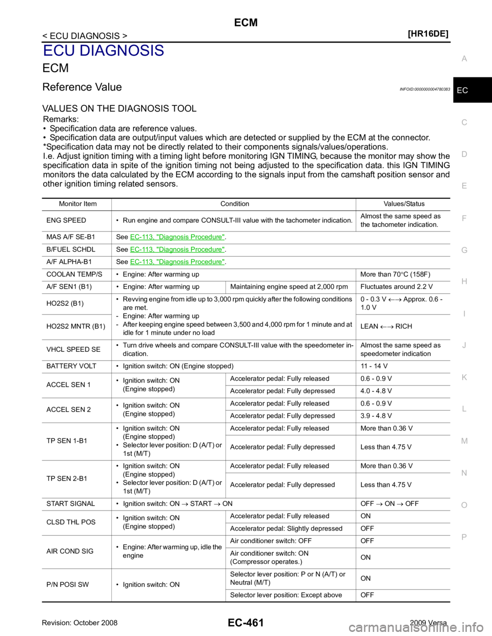
Reference Value INFOID:0000000004780383
VALUES ON THE DIAGNOSIS TOOL Remarks:
• Specification data are reference values.
• Specification data are output/input values which are detected or supplied by the ECM at the connector.
*Specification data may not be directly relat ed to their components signals/values/operations.
I.e. Adjust ignition timing with a timing light before m onitoring IGN TIMING, because the monitor may show the
specification data in spite of the ignition timing not bei ng adjusted to the specification data. this IGN TIMING
monitors the data calculated by the ECM according to the signals input from the camshaft position sensor and
other ignition timing related sensors.
Monitor Item Condition Values/Status
ENG SPEED • Run engine and compare CONSULT-III value with the tachometer indication. Almost the same speed as
the tachometer indication.
MAS A/F SE-B1 See EC-113, " Diagnosis Procedure " .
B/FUEL SCHDL See EC-113, " Diagnosis Procedure " .
A/F ALPHA-B1 See EC-113, " Diagnosis Procedure " .
COOLAN TEMP/S • Engine: After warming up More than 70 °C (158F)
A/F SEN1 (B1) • Engine: After warming up Maintaining engine speed at 2,000 rpm Fluctuates around 2.2 V
HO2S2 (B1) • Revving engine from idle up to 3,000 rpm quickly after the following conditions
are met.
- Engine: After warming up
- After keeping engine speed between 3,500 and 4,000 rpm for 1 minute and at
idle for 1 minute under no load 0 - 0.3 V
←→ Approx. 0.6 -
1.0 V
HO2S2 MNTR (B1) LEAN ←→ RICH
VHCL SPEED SE • Turn drive wheels and compare CONSULT-III value with the speedometer in-
dication. Almost the same speed as
speedometer indication
BATTERY VOLT • Ignition switch: ON (Engine stopped) 11 - 14 V
ACCEL SEN 1 • Ignition switch: ON
(Engine stopped) Accelerator pedal: Fully released 0.6 - 0.9 V
Accelerator pedal: Fully depressed 4.0 - 4.8 V
ACCEL SEN 2 • Ignition switch: ON
(Engine stopped) Accelerator pedal: Fully released 0.6 - 0.9 V
Accelerator pedal: Fully depressed 3.9 - 4.8 V
TP SEN 1-B1 • Ignition switch: ON
(Engine stopped)
• Selector lever position: D (A/T) or 1st (M/T) Accelerator pedal: Fully released More than 0.36 V
Accelerator pedal: Fully depressed Less than 4.75 V
TP SEN 2-B1 • Ignition switch: ON
(Engine stopped)
• Selector lever position: D (A/T) or 1st (M/T) Accelerator pedal: Fully released More than 0.36 V
Accelerator pedal: Fully depressed Less than 4.75 V
START SIGNAL • Ignition switch: ON → START → ON OFF → ON → OFF
CLSD THL POS • Ignition switch: ON
(Engine stopped) Accelerator pedal: Fully released ON
Accelerator pedal: Slightly depressed OFF
AIR COND SIG • Engine: After warming up, idle the
engine Air conditioner switch: OFF OFF
Air conditioner switch: ON
(Compressor operates.) ON
P/N POSI SW • Ignition switch: ON Selector lever position: P or N (A/T) or
Neutral (M/T) ON
Selector lever position: Except above OFF
Page 1848 of 4331
![NISSAN LATIO 2009 Service Repair Manual EC-492< PRECAUTION >
[HR16DE]
PRECAUTIONS
PRECAUTION
PRECAUTIONS
Precaution for Supplemental Restraint Syst em (SRS) "AIR BAG" and "SEAT BELT
PRE-TENSIONER" INFOID:0000000004786987
The Supplemental NISSAN LATIO 2009 Service Repair Manual EC-492< PRECAUTION >
[HR16DE]
PRECAUTIONS
PRECAUTION
PRECAUTIONS
Precaution for Supplemental Restraint Syst em (SRS) "AIR BAG" and "SEAT BELT
PRE-TENSIONER" INFOID:0000000004786987
The Supplemental](/manual-img/5/57359/w960_57359-1847.png)
EC-492< PRECAUTION >
[HR16DE]
PRECAUTIONS
PRECAUTION
PRECAUTIONS
Precaution for Supplemental Restraint Syst em (SRS) "AIR BAG" and "SEAT BELT
PRE-TENSIONER" INFOID:0000000004786987
The Supplemental Restraint System such as “A IR BAG” and “SEAT BELT PRE-TENSIONER”, used along
with a front seat belt, helps to reduce the risk or severi ty of injury to the driver and front passenger for certain
types of collision. This system includes seat belt switch inputs and dual stage front air bag modules. The SRS
system uses the seat belt switches to determine the front air bag deployment, and may only deploy one front
air bag, depending on the severity of a collision and w hether the front occupants are belted or unbelted.
Information necessary to service the system safely is included in the “SUPPLEMENTAL RESTRAINT SYS-
TEM” and “SEAT BELTS” of this Service Manual.
WARNING:
• To avoid rendering the SRS inopera tive, which could increase the risk of personal injury or death in
the event of a collision which would result in air bag inflation, all maintenance must be performed by
an authorized NISS AN/INFINITI dealer.
• Improper maintenance, including in correct removal and installation of the SRS, can lead to personal
injury caused by unintent ional activation of the system. For re moval of Spiral Cable and Air Bag
Module, see the “SUPPLEMEN TAL RESTRAINT SYSTEM”.
• Do not use electrical test equipmen t on any circuit related to the SRS unless instructed to in this
Service Manual. SRS wiring harn esses can be identified by yellow and/or orange harnesses or har-
ness connectors.
PRECAUTIONS WHEN USING POWER TOOLS (AIR OR ELECTRIC) AND HAMMERS
WARNING:
• When working near the Airbag Diagnosis Sensor Unit or other Airbag System sensors with the igni-
tion ON or engine running, DO NOT use air or electri c power tools or strike near the sensor(s) with a
hammer. Heavy vibration could activate the sensor( s) and deploy the air bag(s), possibly causing
serious injury.
• When using air or electric power tools or hammers , always switch the ignition OFF, disconnect the
battery, and wait at least 3 minu tes before performing any service.
Precaution for Procedure without Cowl Top Cover INFOID:0000000004786988
When performing the procedure after removing cowl top cover, cover
the lower end of windshield with urethane, etc.
On Board Diagnosis (OBD) S ystem of Engine and A/T INFOID:0000000004780394
The ECM has an on board diagnostic system. It will light up the malfunction indicator lamp (MIL) to warn the
driver of a malfunction causing emission deterioration.
CAUTION:
• Be sure to turn the ignition sw itch OFF and disconnect the negative battery cable before any repair
or inspection work. The open/short circuit of re lated switches, sensors, solenoid valves, etc. will
cause the MIL to light up.
• Be sure to connect and lock the connectors secure ly after work. A loose (unlocked) connector will
cause the MIL to light up due to the open circuit. (Be sure the connector is free from water, grease,
dirt, bent terminals, etc.)
• Certain systems and components, especially those related to OBD, may use a new style slide-lock-
ing type harness connector. For descrip tion and how to disconnect, refer to PG-64, " Description " .PIIB3706J
Page 1849 of 4331
![NISSAN LATIO 2009 Service Repair Manual PRECAUTIONS
EC-493
< PRECAUTION >
[HR16DE] C
D E
F
G H
I
J
K L
M A EC
NP
O
• Be sure to route and secure the harnesses properly
after work. The interference of the harness with
a bracket, etc. may NISSAN LATIO 2009 Service Repair Manual PRECAUTIONS
EC-493
< PRECAUTION >
[HR16DE] C
D E
F
G H
I
J
K L
M A EC
NP
O
• Be sure to route and secure the harnesses properly
after work. The interference of the harness with
a bracket, etc. may](/manual-img/5/57359/w960_57359-1848.png)
PRECAUTIONS
EC-493
< PRECAUTION >
[HR16DE] C
D E
F
G H
I
J
K L
M A EC
NP
O
• Be sure to route and secure the harnesses properly
after work. The interference of the harness with
a bracket, etc. may cause the MIL to li ght up due to the short circuit.
• Be sure to connect rubber tubes properly afte r work. A misconnected or disconnected rubber tube
may cause the MIL to light up due to the malfuncti on of the EVAP system or fuel injection system,
etc.
• Be sure to erase the unnecessary malfunction informa tion (repairs completed) from the ECM and
TCM (Transmission control module) before returning the vehicle to the customer.
General Precautions INFOID:0000000004780395
• Always use a 12 volt battery as power source.
• Do not attempt to disconnect battery cables while engine is
running.
• Before connecting or disc onnecting the ECM harness con-
nector, turn ignition switch OFF and disconnect negative bat-
tery cable. Failure to do so may damage the ECM because
battery voltage is applied to ECM even if ignition switch is
turned OFF.
• Before removing parts, turn ig nition switch OFF and then dis-
connect negative battery cable.
• Do not disassemble ECM.
• If a battery cable is disconnect ed, the memory will return to
the ECM value.
The ECM will now start to self-control at its initial value. Thus,
engine operation can vary slight ly in this case. However, this
is not an indication of a malf unction. Do not replace parts
because of a slight variation.
• If the battery is disconnected, the following emission-related
diagnostic information will be cleared within 24 hours.
- Diagnostic trouble codes
- 1st trip diagnostic trouble codes
- Freeze frame data
- 1st trip freeze frame data
- System readiness test (SRT) codes
- Test values
• When connecting ECM harness c onnector (1), fasten (B) it
securely with a lever as far as it will go as shown in the figure.
• When connecting or disconnect ing pin connectors into or
from ECM, take care not to damage pin terminals (bend or
break).
Make sure that there are not any bends or breaks on ECM pin
terminal, when connecting pin connectors.
• Securely connect ECM harness connectors.
A poor connection can cause an extremely high (surge) volt-
age to develop in coil and cond enser, thus resulting in dam-
age to ICs.
• Keep engine control system harness at least 10 cm (4 in) away
from adjacent harness, to prevent engine control system mal- SEF289H
2. ECM
A. Loosen PBIA9222J
PBIB2947E
PBIB0090E