Page 1867 of 1903
Downloaded from www.Manualslib.com manuals search engine Overview
Front Fuse And Relay Box
GENERAL INFORMATION
LTSMW170005T
16
16–41Chery Automobile Co., Ltd.
Page 1868 of 1903
Downloaded from www.Manualslib.com manuals search engine Body Fuse and Relay Box
Description
The body fuse and relay box houses many of the fuses and relays for the vehicle’s electrical system. The body fuse
and relay box is situated on the left front side of the interior of the cabin and under the instrument panel, which is
mounted on the cross beam of the instrument panel. All the fuses and relays cannot be serviced it must be replaced
as a unit.
Operation
When a circuit fails, the fuse will blow and remove current from the circuit.
Turn off the ignition switch, and then replace the fuse.
GENERAL INFORMATION
16–42Chery Automobile Co., Ltd.
Page 1869 of 1903
Downloaded from www.Manualslib.com manuals search engine Overview
Body Fuse And Relay Box
GENERAL INFORMATION
LTSMW170006T
16
16–43Chery Automobile Co., Ltd.
Page 1875 of 1903
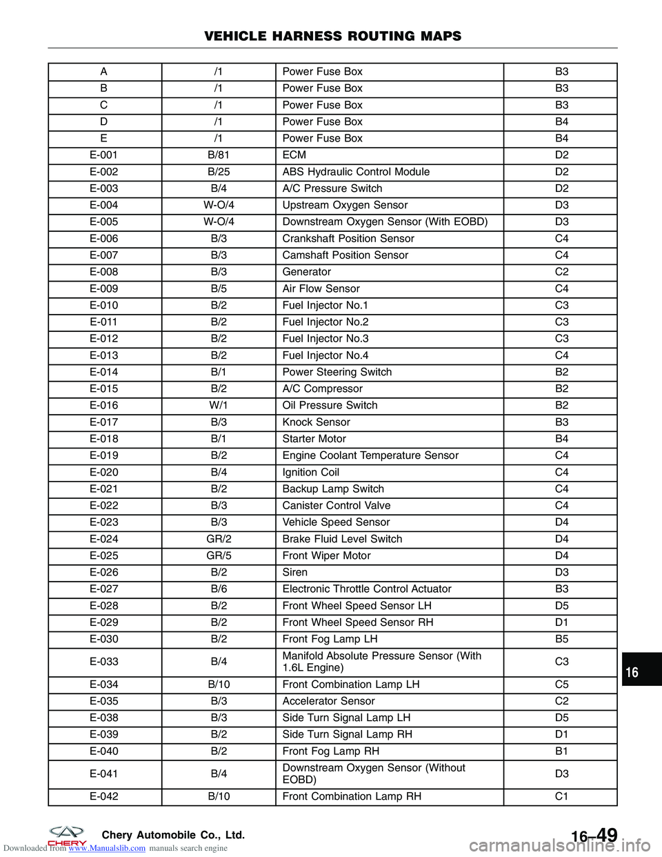
Downloaded from www.Manualslib.com manuals search engine A/1Power Fuse Box B3
B /1Power Fuse Box B3
C /1Power Fuse Box B3
D /1Power Fuse Box B4
E /1Power Fuse Box B4
E-001 B/81 ECM D2
E-002 B/25 ABS Hydraulic Control Module D2
E-003 B/4A/C Pressure Switch D2
E-004 W-O/4 Upstream Oxygen Sensor D3
E-005 W-O/4 Downstream Oxygen Sensor (With EOBD) D3
E-006 B/3Crankshaft Position Sensor C4
E-007 B/3Camshaft Position Sensor C4
E-008 B/3Generator C2
E-009 B/5Air Flow Sensor C4
E-010 B/2Fuel Injector No.1 C3
E-011 B/2Fuel Injector No.2 C3
E-012 B/2Fuel Injector No.3 C3
E-013 B/2Fuel Injector No.4 C4
E-014 B/1Power Steering Switch B2
E-015 B/2A/C Compressor B2
E-016 W/1 Oil Pressure Switch B2
E-017 B/3Knock Sensor B3
E-018 B/1Starter Motor B4
E-019 B/2Engine Coolant Temperature Sensor C4
E-020 B/4Ignition Coil C4
E-021 B/2Backup Lamp Switch C4
E-022 B/3Canister Control Valve C4
E-023 B/3Vehicle Speed Sensor D4
E-024 GR/2 Brake Fluid Level Switch D4
E-025 GR/5 Front Wiper Motor D4
E-026 B/2Siren D3
E-027 B/6Electronic Throttle Control Actuator B3
E-028 B/2Front Wheel Speed Sensor LH D5
E-029 B/2Front Wheel Speed Sensor RH D1
E-030 B/2Front Fog Lamp LH B5
E-033 B/4Manifold Absolute Pressure Sensor (With
1.6L Engine) C3
E-034 B/10 Front Combination Lamp LH C5
E-035 B/3Accelerator Sensor C2
E-038 B/3Side Turn Signal Lamp LH D5
E-039 B/2Side Turn Signal Lamp RH D1
E-040 B/2Front Fog Lamp RH B1
E-041 B/4Downstream Oxygen Sensor (Without
EOBD) D3
E-042 B/10 Front Combination Lamp RH C1
VEHICLE HARNESS ROUTING MAPS
16
16–49Chery Automobile Co., Ltd.
Page 1876 of 1903
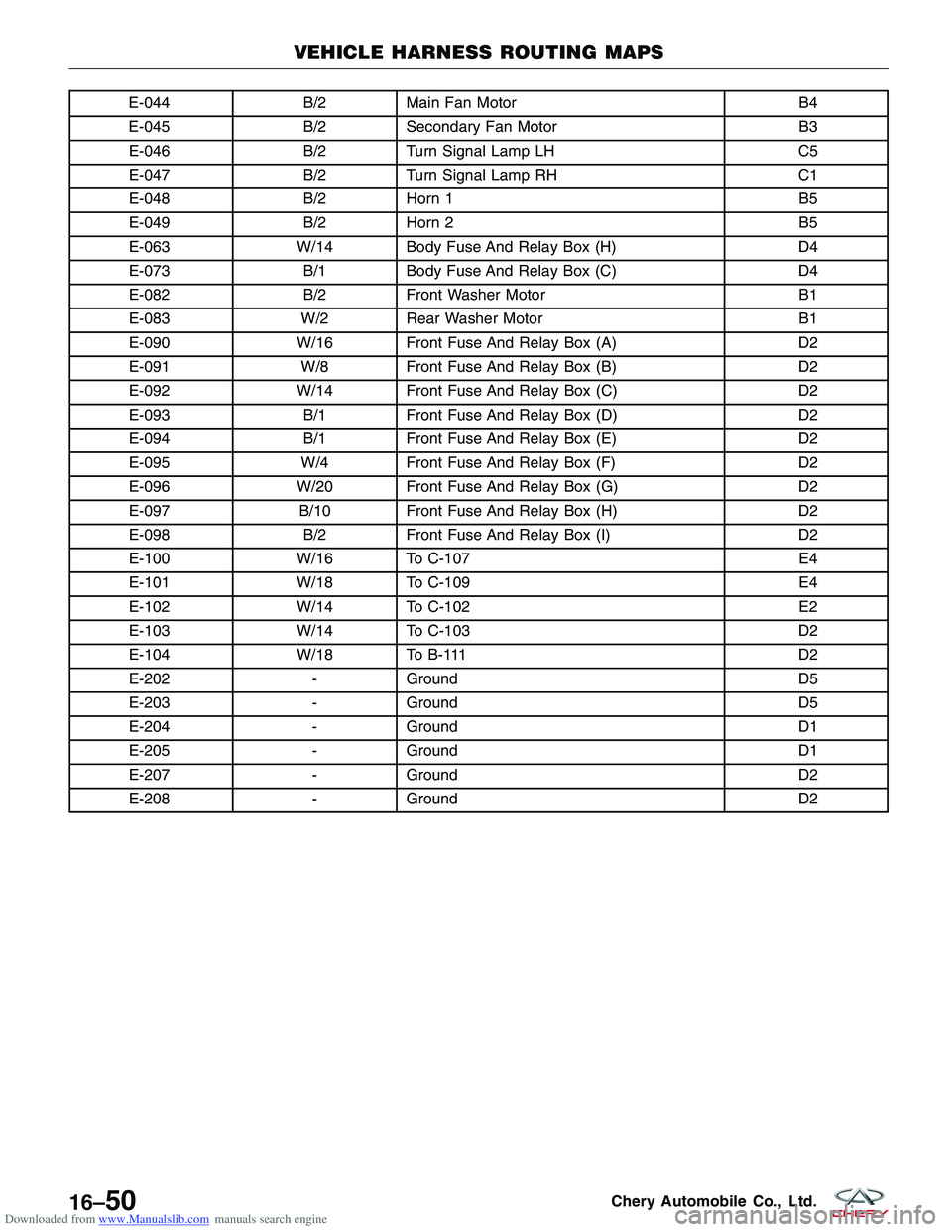
Downloaded from www.Manualslib.com manuals search engine E-044B/2Main Fan Motor B4
E-045 B/2Secondary Fan Motor B3
E-046 B/2Turn Signal Lamp LH C5
E-047 B/2Turn Signal Lamp RH C1
E-048 B/2Horn 1 B5
E-049 B/2Horn 2 B5
E-063 W/14 Body Fuse And Relay Box (H) D4
E-073 B/1Body Fuse And Relay Box (C) D4
E-082 B/2Front Washer Motor B1
E-083 W/2 Rear Washer Motor B1
E-090 W/16 Front Fuse And Relay Box (A) D2
E-091 W/8 Front Fuse And Relay Box (B) D2
E-092 W/14 Front Fuse And Relay Box (C) D2
E-093 B/1Front Fuse And Relay Box (D) D2
E-094 B/1Front Fuse And Relay Box (E) D2
E-095 W/4 Front Fuse And Relay Box (F) D2
E-096 W/20 Front Fuse And Relay Box (G) D2
E-097 B/10 Front Fuse And Relay Box (H) D2
E-098 B/2Front Fuse And Relay Box (I) D2
E-100 W/16 To C-107 E4
E-101 W/18 To C-109 E4
E-102 W/14 To C-102 E2
E-103 W/14 To C-103 D2
E-104 W/18 To B-111 D2
E-202 -Ground D5
E-203 -Ground D5
E-204 -Ground D1
E-205 -Ground D1
E-207 -Ground D2
E-208 -Ground D2
VEHICLE HARNESS ROUTING MAPS
16–50Chery Automobile Co., Ltd.
Page 1882 of 1903
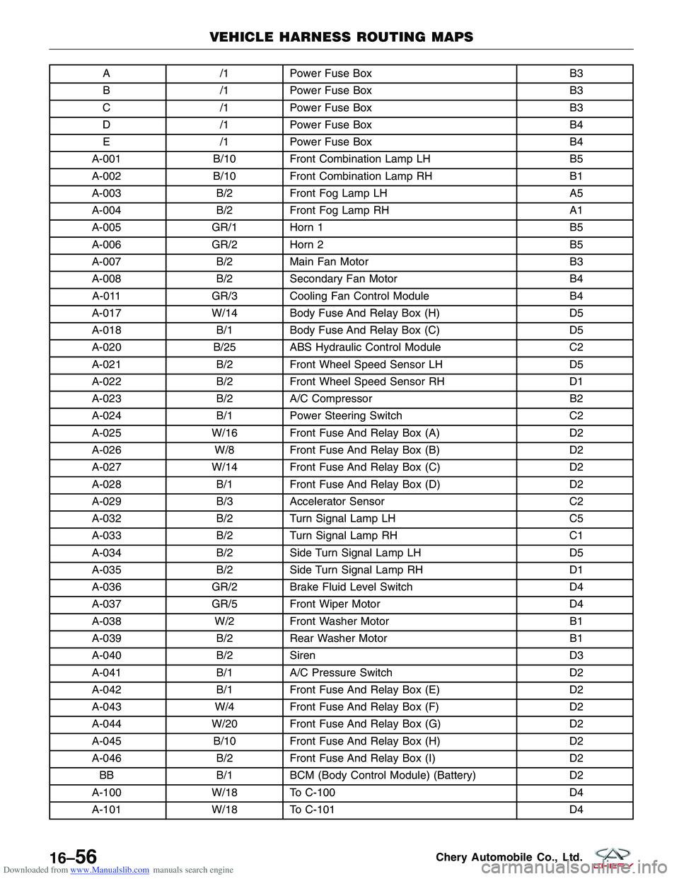
Downloaded from www.Manualslib.com manuals search engine A/1Power Fuse Box B3
B /1Power Fuse Box B3
C /1Power Fuse Box B3
D /1Power Fuse Box B4
E /1Power Fuse Box B4
A-001 B/10 Front Combination Lamp LH B5
A-002 B/10 Front Combination Lamp RH B1
A-003 B/2Front Fog Lamp LH A5
A-004 B/2Front Fog Lamp RH A1
A-005 GR/1 Horn 1 B5
A-006 GR/2 Horn 2 B5
A-007 B/2Main Fan Motor B3
A-008 B/2Secondary Fan Motor B4
A-011 GR/3 Cooling Fan Control Module B4
A-017 W/14 Body Fuse And Relay Box (H) D5
A-018 B/1Body Fuse And Relay Box (C) D5
A-020 B/25 ABS Hydraulic Control Module C2
A-021 B/2Front Wheel Speed Sensor LH D5
A-022 B/2Front Wheel Speed Sensor RH D1
A-023 B/2A/C Compressor B2
A-024 B/1Power Steering Switch C2
A-025 W/16 Front Fuse And Relay Box (A) D2
A-026 W/8 Front Fuse And Relay Box (B) D2
A-027 W/14 Front Fuse And Relay Box (C) D2
A-028 B/1Front Fuse And Relay Box (D) D2
A-029 B/3Accelerator Sensor C2
A-032 B/2Turn Signal Lamp LH C5
A-033 B/2Turn Signal Lamp RH C1
A-034 B/2Side Turn Signal Lamp LH D5
A-035 B/2Side Turn Signal Lamp RH D1
A-036 GR/2 Brake Fluid Level Switch D4
A-037 GR/5 Front Wiper Motor D4
A-038 W/2 Front Washer Motor B1
A-039 B/2Rear Washer Motor B1
A-040 B/2Siren D3
A-041 B/1A/C Pressure Switch D2
A-042 B/1Front Fuse And Relay Box (E) D2
A-043 W/4 Front Fuse And Relay Box (F) D2
A-044 W/20 Front Fuse And Relay Box (G) D2
A-045 B/10 Front Fuse And Relay Box (H) D2
A-046 B/2Front Fuse And Relay Box (I) D2
BB B/1BCM (Body Control Module) (Battery) D2
A-100 W/18 To C-100 D4
A-101 W/18 To C-101 D4
VEHICLE HARNESS ROUTING MAPS
16–56Chery Automobile Co., Ltd.
Page 1885 of 1903
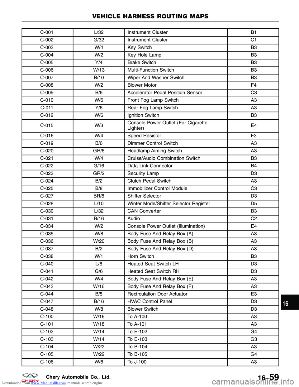
Downloaded from www.Manualslib.com manuals search engine C-001L/32 Instrument Cluster B1
C-002 G/32 Instrument Cluster C1
C-003 W/4 Key Switch B3
C-004 W/2 Key Hole Lamp B3
C-005 Y/4Brake Switch B3
C-006 W/13 Multi-Function Switch B3
C-007 B/10 Wiper And Washer Switch B3
C-008 W/2 Blower Motor F4
C-009 B/6Accelerator Pedal Position Sensor C3
C-010 W/6 Front Fog Lamp Switch A3
C-011 Y/6Rear Fog Lamp Switch A3
C-012 W/6 Ignition Switch B3
C-015 W/3Console Power Outlet (For Cigarette
Lighter) E4
C-016 W/4 Speed Resistor F3
C-019 B/6Dimmer Control Switch A3
C-020 GR/6 Headlamp Aiming Switch A3
C-021 W/4 Cruise/Audio Combination Switch B3
C-022 G/16 Data Link Connector B4
C-023 GR/2 Security Lamp D3
C-024 B/2Clutch Pedal Switch A3
C-025 B/8Immobilizer Control Module C3
C-027 BR/6 Shifter Selector D3
C-028 L/10 Winter Mode/Shifter Selector Register D5
C-030 L/32 CAN Converter B3
C-031 B/16 Audio C2
C-034 W/2 Console Power Outlet (Illumination) E4
C-035 W/8 Body Fuse And Relay Box (A) A3
C-036 W/20 Body Fuse And Relay Box (B) A3
C-037 B/2Body Fuse And Relay Box (D) A3
C-038 W/1 Horn Switch B3
C-040 L/6Heated Seat Switch LH D3
C-041 G/6Heated Seat Switch RH D3
C-042 W/4 Body Fuse And Relay Box (E) A3
C-043 W/16 Body Fuse And Relay Box (F) A3
C-044 B/5Recirculation Door Actuator E3
C-047 B/16 HVAC Control Panel D3
C-048 W/8 Blower Switch D3
C-100 W/16 To A-100 A3
C-101 W/18 To A-101 A3
C-102 W/14 To E-102 G4
C-103 W/14 To E-103 G3
C-104 W/22 To B-104 A3
C-105 W/22 To B-105 G4
C-106 W/6 To J-100 A3
VEHICLE HARNESS ROUTING MAPS
16
16–59Chery Automobile Co., Ltd.
Page 1888 of 1903
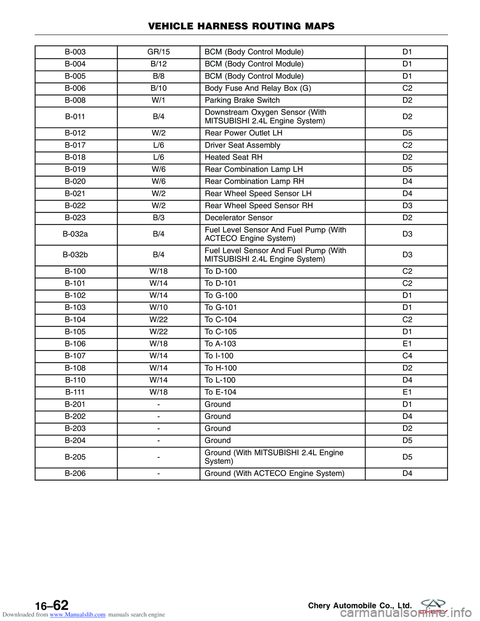
Downloaded from www.Manualslib.com manuals search engine B-003GR/15 BCM (Body Control Module) D1
B-004 B/12 BCM (Body Control Module) D1
B-005 B/8BCM (Body Control Module) D1
B-006 B/10 Body Fuse And Relay Box (G) C2
B-008 W/1 Parking Brake Switch D2
B-011 B/4Downstream Oxygen Sensor (With
MITSUBISHI 2.4L Engine System) D2
B-012 W/2 Rear Power Outlet LH D5
B-017 L/6Driver Seat Assembly C2
B-018 L/6Heated Seat RH D2
B-019 W/6 Rear Combination Lamp LH D5
B-020 W/6 Rear Combination Lamp RH D4
B-021 W/2 Rear Wheel Speed Sensor LH D4
B-022 W/2 Rear Wheel Speed Sensor RH D3
B-023 B/3Decelerator Sensor D2
B-032a B/4Fuel Level Sensor And Fuel Pump (With
ACTECO Engine System) D3
B-032b B/4Fuel Level Sensor And Fuel Pump (With
MITSUBISHI 2.4L Engine System) D3
B-100 W/18 To D-100 C2
B-101 W/14 To D-101 C2
B-102 W/14 To G-100 D1
B-103 W/10 To G-101 D1
B-104 W/22 To C-104 C2
B-105 W/22 To C-105 D1
B-106 W/18 To A-103 E1
B-107 W/14 To I-100 C4
B-108 W/14 To H-100 D2
B-110 W/14 To L-100 D4
B-111 W/18 To E-104 E1
B-201 -Ground D1
B-202 -Ground D4
B-203 -Ground D2
B-204 -Ground D5
B-205 -Ground (With MITSUBISHI 2.4L Engine
System) D5
B-206 -Ground (With ACTECO Engine System) D4
VEHICLE HARNESS ROUTING MAPS
16–62Chery Automobile Co., Ltd.