Page 1128 of 1903
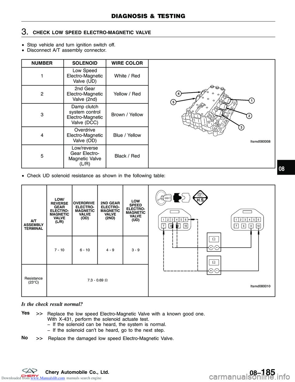
Downloaded from www.Manualslib.com manuals search engine 3.CHECK LOW SPEED ELECTRO-MAGNETIC VALVE
• Stop vehicle and turn ignition switch off.
• Disconnect A/T assembly connector.
NUMBER SOLENOID WIRE COLOR
1 Low Speed
Electro-Magnetic Valve (UD) White / Red
2 2nd Gear
Electro-Magnetic Valve (2nd) Yellow / Red
3 Damp clutch
system control
Electro-Magnetic Valve (DCC) Brown / Yellow
4 Overdrive
Electro-Magnetic Valve (OD) Blue / Yellow
5 Low/reverse
Gear Electro-
Magnetic Valve (L/R) Black / Red
• Check UD solenoid resistance as shown in the following table:
A/T
ASSEMBLY TERMINAL LOW/
REVERSE GEAR
ELECTRO-
MAGNETIC VA LV E(L/R) OVERDRIVE
ELECTRO-
MAGNETIC VA LV E(OD) 2ND GEAR
ELECTRO-
MAGNETIC VA LV E(2ND) LOW
SPEED
ELECTRO-
MAGNETIC VA LV E(UD)
7-10 6-10 4-9 3-9
Resistance (23°C) 7.3 - 0.69
�
Is the check result normal?
Ye s>>Replace the low speed Electro-Magnetic Valve with a known good one.
With X-431, perform the solenoid actuate test.
� If the solenoid can be heard, the system is normal.
� If the solenoid can’t be heard, go to the next step.
No
>>Replace the damaged low speed Electro-Magnetic Valve.
DIAGNOSIS & TESTING
08
08–185Chery Automobile Co., Ltd.
Page 1134 of 1903
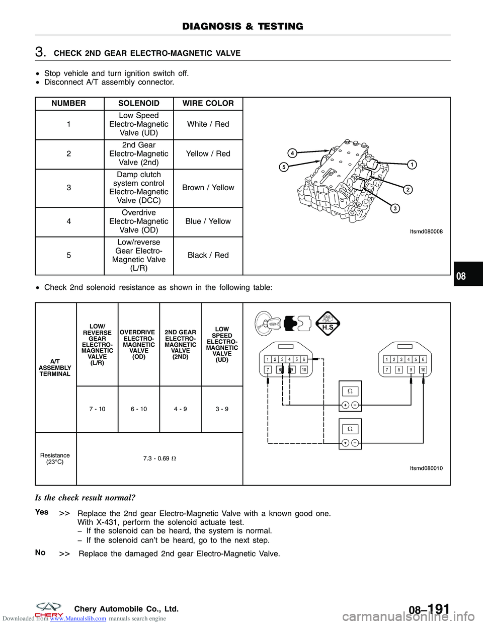
Downloaded from www.Manualslib.com manuals search engine 3.CHECK 2ND GEAR ELECTRO-MAGNETIC VALVE
• Stop vehicle and turn ignition switch off.
• Disconnect A/T assembly connector.
NUMBER SOLENOID WIRE COLOR
1 Low Speed
Electro-Magnetic Valve (UD) White / Red
2 2nd Gear
Electro-Magnetic Valve (2nd) Yellow / Red
3 Damp clutch
system control
Electro-Magnetic Valve (DCC) Brown / Yellow
4 Overdrive
Electro-Magnetic Valve (OD) Blue / Yellow
5 Low/reverse
Gear Electro-
Magnetic Valve (L/R) Black / Red
• Check 2nd solenoid resistance as shown in the following table:
A/T
ASSEMBLY TERMINAL LOW/
REVERSE GEAR
ELECTRO-
MAGNETIC VA LV E(L/R) OVERDRIVE
ELECTRO-
MAGNETIC VA LV E(OD) 2ND GEAR
ELECTRO-
MAGNETIC VA LV E(2ND) LOW
SPEED
ELECTRO-
MAGNETIC VA LV E(UD)
7-10 6-10 4-9 3-9
Resistance (23°C) 7.3 - 0.69
�
Is the check result normal?
Ye s>>Replace the 2nd gear Electro-Magnetic Valve with a known good one.
With X-431, perform the solenoid actuate test.
� If the solenoid can be heard, the system is normal.
� If the solenoid can’t be heard, go to the next step.
No
>>Replace the damaged 2nd gear Electro-Magnetic Valve.
DIAGNOSIS & TESTING
08
08–191Chery Automobile Co., Ltd.
Page 1140 of 1903
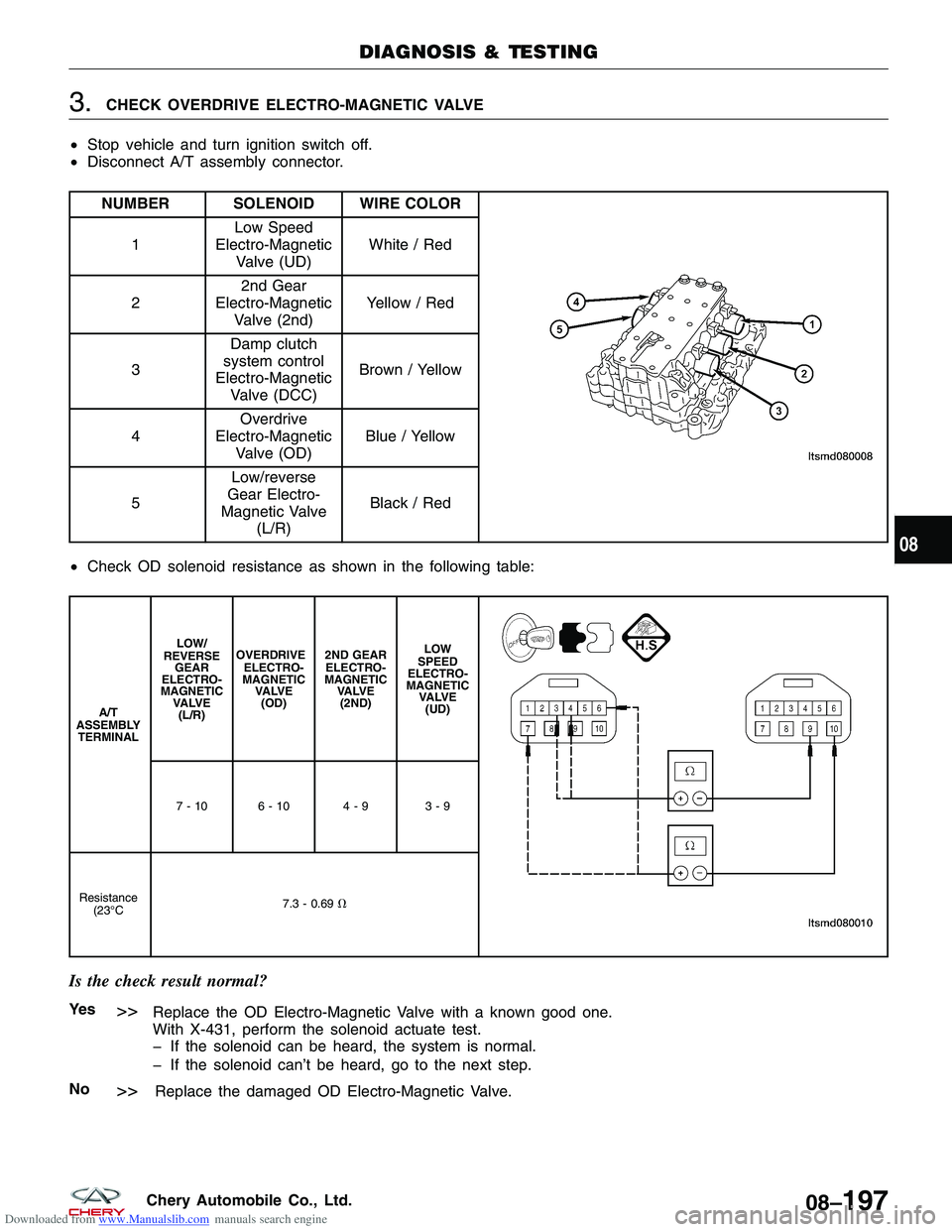
Downloaded from www.Manualslib.com manuals search engine 3.CHECK OVERDRIVE ELECTRO-MAGNETIC VALVE
• Stop vehicle and turn ignition switch off.
• Disconnect A/T assembly connector.
NUMBER SOLENOID WIRE COLOR
1 Low Speed
Electro-Magnetic Valve (UD) White / Red
2 2nd Gear
Electro-Magnetic Valve (2nd) Yellow / Red
3 Damp clutch
system control
Electro-Magnetic Valve (DCC) Brown / Yellow
4 Overdrive
Electro-Magnetic Valve (OD) Blue / Yellow
5 Low/reverse
Gear Electro-
Magnetic Valve (L/R) Black / Red
• Check OD solenoid resistance as shown in the following table:
A/T
ASSEMBLY TERMINAL LOW/
REVERSE GEAR
ELECTRO-
MAGNETIC VA LV E(L/R) OVERDRIVE
ELECTRO-
MAGNETIC VA LV E(OD) 2ND GEAR
ELECTRO-
MAGNETIC VA LV E(2ND) LOW
SPEED
ELECTRO-
MAGNETIC VA LV E(UD)
7-10 6-10 4-9 3-9
Resistance (23°C 7.3 - 0.69
�
Is the check result normal?
Ye s>>Replace the OD Electro-Magnetic Valve with a known good one.
With X-431, perform the solenoid actuate test.
� If the solenoid can be heard, the system is normal.
� If the solenoid can’t be heard, go to the next step.
No
>>Replace the damaged OD Electro-Magnetic Valve.
DIAGNOSIS & TESTING
08
08–197Chery Automobile Co., Ltd.
Page 1143 of 1903
Downloaded from www.Manualslib.com manuals search engine 36 - Damper Clutch System Control Solenoid Malfunction
DIAGNOSIS & TESTING
LTSMW080005T
08–200Chery Automobile Co., Ltd.
Page 1144 of 1903
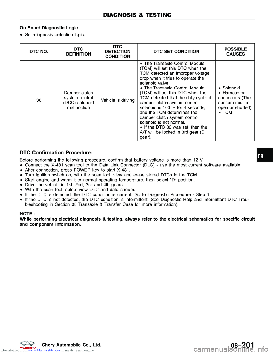
Downloaded from www.Manualslib.com manuals search engine On Board Diagnostic Logic
•Self-diagnosis detection logic.
DTC NO. DTC
DEFINITION DTC
DETECTION CONDITION DTC SET CONDITION
POSSIBLE
CAUSES
36 Damper clutch
system control
(DCC) solenoid malfunction Vehicle is driving •
The Transaxle Control Module
(TCM) will set this DTC when the
TCM detected an improper voltage
drop when it tries to operate the
solenoid valve.
• The Transaxle Control Module
(TCM) will set this DTC when the
TCM detected that the duty cycle of
damper clutch system control
solenoid is 100 % for 4 seconds,
and the TCM determines the
damper clutch system control
solenoid is not normal.
• If the DTC 36 was set, then the
A/T will be locked in 3rd gear (D
gear). •
Solenoid
• Harness or
connectors (The
sensor circuit is
open or shorted)
• TCM
DTC Confirmation Procedure:
Before performing the following procedure, confirm that battery voltage is more than 12 V.
• Connect the X-431 scan tool to the Data Link Connector (DLC) - use the most current software available.
• After connection, press POWER key to start X-431.
• Turn ignition switch on, with the scan tool, view and erase stored DTCs in the TCM.
• Start engine and warm it to normal operating temperature, then select �D�position.
• Drive the vehicle in 1st, 2nd, 3rd and 4th gears.
• With the scan tool, select view DTC and data stream.
• If the DTC is detected, the DTC condition is current. Go to Diagnostic Procedure - Step 1.
• If the DTC is not detected, the DTC condition is intermittent (See Diagnostic Help and Intermittent DTC Trou-
bleshooting in Section 08 Transaxle & Transfer Case for more information).
NOTE :
While performing electrical diagnosis & testing, always refer to the electrical schematics for specific circuit
and component information.
DIAGNOSIS & TESTING
08
08–201Chery Automobile Co., Ltd.
Page 1146 of 1903
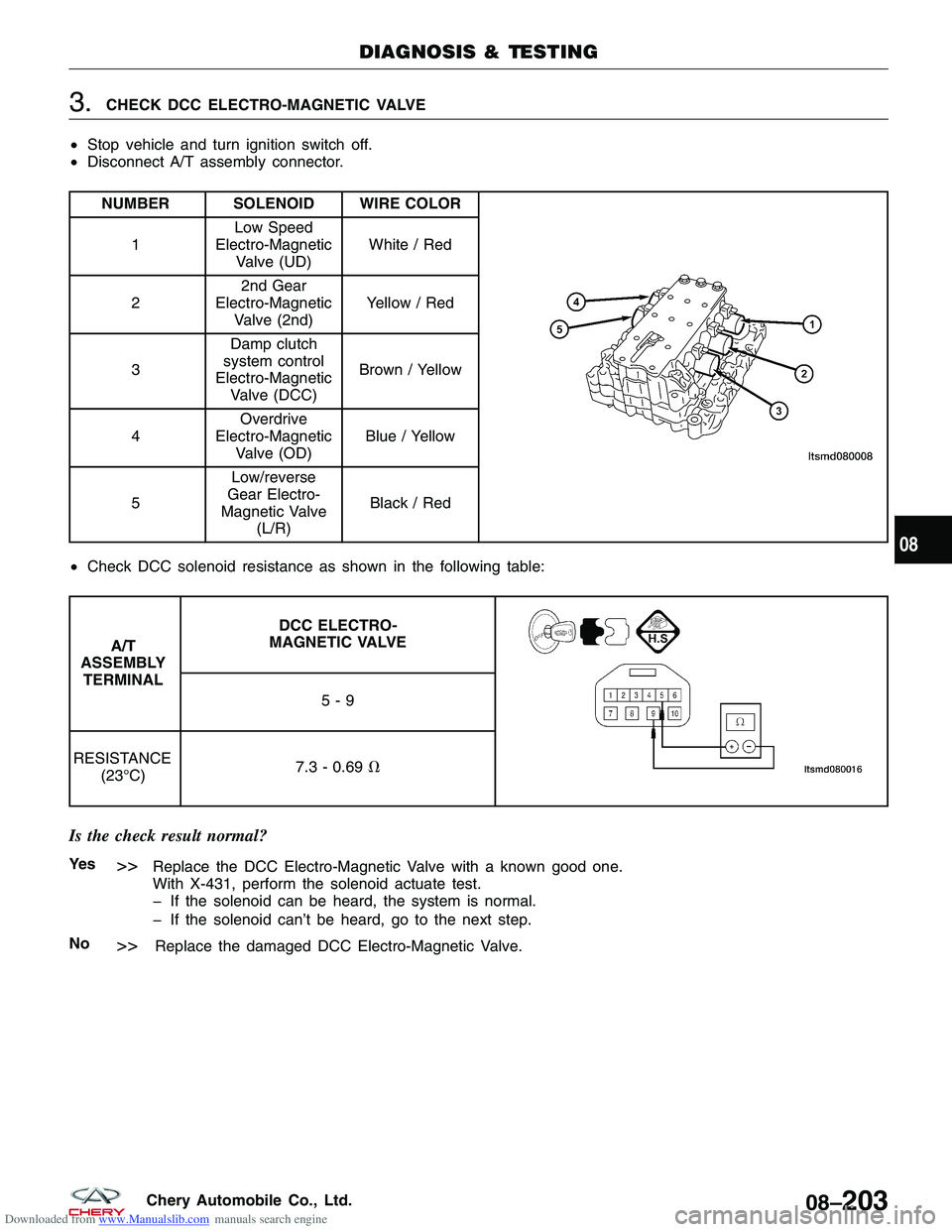
Downloaded from www.Manualslib.com manuals search engine 3.CHECK DCC ELECTRO-MAGNETIC VALVE
• Stop vehicle and turn ignition switch off.
• Disconnect A/T assembly connector.
NUMBER SOLENOID WIRE COLOR
1 Low Speed
Electro-Magnetic Valve (UD) White / Red
2 2nd Gear
Electro-Magnetic Valve (2nd) Yellow / Red
3 Damp clutch
system control
Electro-Magnetic Valve (DCC) Brown / Yellow
4 Overdrive
Electro-Magnetic Valve (OD) Blue / Yellow
5 Low/reverse
Gear Electro-
Magnetic Valve (L/R) Black / Red
• Check DCC solenoid resistance as shown in the following table:
A/T
ASSEMBLY TERMINAL DCC ELECTRO-
MAGNETIC VALVE
5-9
RESISTANCE (23°C) 7.3 - 0.69
�
Is the check result normal?
Ye s>>Replace the DCC Electro-Magnetic Valve with a known good one.
With X-431, perform the solenoid actuate test.
� If the solenoid can be heard, the system is normal.
� If the solenoid can’t be heard, go to the next step.
No
>>Replace the damaged DCC Electro-Magnetic Valve.
DIAGNOSIS & TESTING
08
08–203Chery Automobile Co., Ltd.
Page 1150 of 1903
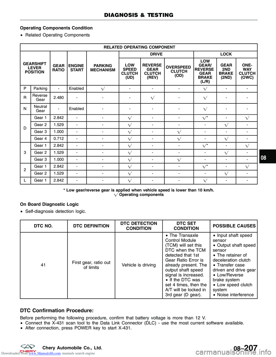
Downloaded from www.Manualslib.com manuals search engine Operating Components Condition
•Related Operating Components
RELATED OPERATING COMPONENT
GEARSHIFT LEVER
POSITION GEAR
RATIO ENGINE
START PARKING
MECHANISM DRIVE
LOCK
LOW
SPEED
CLUTCH (UD) REVERSE
GEAR
CLUTCH (REV) OVERSPEED
CLUTCH(OD) LOW
GEAR/
REVERSE GEAR
BRAKE (L/R) GEAR
2ND
BRAKE (2ND) ONE-
WAY
CLUTCH (OWC)
P Parking - Enabled �-- - �--
R Reverse
Gear 2.480 -
--� -�--
N Neutral
Gear - Enabled -
-- -�--
D Gear 1 2.842 -
-�-- �*-�
Gear 2 1.529 - -�--- �-
Gear 3 1.000 - -�- � ---
Gear 4 0.712 - -�- � -� -
3 Gear 1 2.842 -
-�-- �*-�
Gear 2 1.529 - -�--- �-
Gear 3 1.000 - -�- � ---
2 Gear 1 2.842 -
-�-- �*- �
Gear 21.529
- -�--- �-
L Gear 1 2.842 - -�-- �--
* Low gear/reverse gear is applied when vehicle speed is lower than 10 km/h. �Operating components
On Board Diagnostic Logic
•Self-diagnosis detection logic.
DTC NO. DTC DEFINITION DTC DETECTION
CONDITION DTC SET
CONDITION POSSIBLE CAUSES
41 First gear, ratio out
of limits Vehicle is driving •
The Transaxle
Control Module
(TCM) will set this
DTC when the TCM
detected that 1st
Gear Ratio Error is
already present. The
output shaft speed
signal is increased.
• If the DTC was
set 4 times, then the
A/T will be locked in
3rd gear (D gear). •
Input shaft speed
sensor
• Output shaft speed
sensor
• The retainer of
deceleration clutch
• Transfer case
driven and drive gear
• Low/Reverse
brake system
• Low speed clutch
system
• Noise interference
DTC Confirmation Procedure:
Before performing the following procedure, confirm that battery voltage is more than 12 V.
• Connect the X-431 scan tool to the Data Link Connector (DLC) - use the most current software available.
• After connection, press POWER key to start X-431.
DIAGNOSIS & TESTING
08
08–207Chery Automobile Co., Ltd.
Page 1152 of 1903
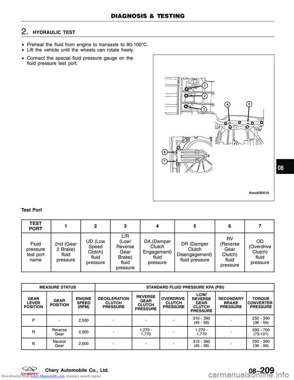
Downloaded from www.Manualslib.com manuals search engine 2.HYDRAULIC TEST
• Preheat the fluid from engine to transaxle to 80-100°C.
• Lift the vehicle until the wheels can rotate freely.
• Connect the special fluid pressure gauge on the
fluid pressure test port.
Test Port
TEST
PORT 123 4 5 6 7
Fluid
pressure test port name 2nd (Gear
2 Brake) fluid
pressure UD (Low
Speed
Clutch) fluid
pressure L/R
(Low/
Reverse Gear
Brake) fluid
pressure DA (Damper
Clutch
Engagement) fluid
pressure DR (Damper
Clutch
Disengagement) fluid pressure RV
(Reverse Gear
Clutch) fluid
pressure OD
(Overdrive Clutch)fluid
pressure
MEASURE STATUS STANDARD FLUID PRESSURE KPA (PSI)
GEAR
LEVER
POSITION GEAR
POSITION ENGINE
SPEED (RPM) DECELERATION
CLUTCH
PRESSURE REVERSE
GEAR
CLUTCH
PRESSURE OVERDRIVE
CLUTCH
PRESSURE LOW/
REVERSE GEAR
CLUTCH
PRESSURE SECONDARY
BRAKE
PRESSURE TORQUE
CONVERTER PRESSURE
P - 2,500 ---310 - 390
(45 - 56) -250 - 390
(36 - 56)
R Reverse
Gear 2,500
-1,270 -
1,770 -1,270 -
1,770 -500 - 700
(73-101)
N Neutral
Gear 2,500
---310 - 390
(45 - 56) -250 - 390
(36 - 56)
DIAGNOSIS & TESTING
LTSMD080018
08
08–209Chery Automobile Co., Ltd.