Page 1086 of 1903
Downloaded from www.Manualslib.com manuals search engine F4A4 AUTOMATIC TRANSAXLE
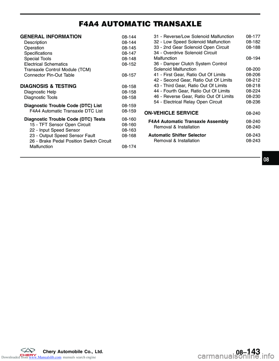
GENERAL INFORMATION08-144
Description 08-144
Operation 08-145
Specifications 08-147
Special Tools 08-148
Electrical Schematics 08-152
Transaxle Control Module (TCM)
Connector Pin-Out Table 08-157
DIAGNOSIS & TESTING08-158
Diagnostic Help 08-158
Diagnostic Tools 08-158
Diagnostic Trouble Code (DTC) List 08-159
F4A4 Automatic Transaxle DTC List 08-159
Diagnostic Trouble Code (DTC) Tests 08-160
15 - TFT Sensor Open Circuit 08-160
22 - Input Speed Sensor 08-163
23 - Output Speed Sensor Fault 08-168
26 - Brake Pedal Position Switch Circuit
Malfunction 08-17431 - Reverse/Low Solenoid Malfunction 08-177
32 - Low Speed Solenoid Malfunction 08-182
33 - 2nd Gear Solenoid Open Circuit 08-188
34 - Overdrive Solenoid Circuit
Malfunction
08-194
36 - Damper Clutch System Control
Solenoid Malfunction 08-200
41 - First Gear, Ratio Out Of Limits 08-206
42 - Second Gear, Ratio Out Of Limits 08-212
43 - Third Gear, Ratio Out Of Limits 08-218
44 - Fourth Gear, Ratio Out Of Limits 08-224
46 - Reverse Gear, Ratio Out Of Limits 08-230
54 - Electrical Relay Open Circuit 08-236
ON-VEHICLE SERVICE08-240
F4A4 Automatic Transaxle Assembly 08-240
Removal & Installation 08-240
Automatic Shifter Selector 08-243
Removal & Installation 08-243
08
08–143Chery Automobile Co., Ltd.
Page 1087 of 1903
Downloaded from www.Manualslib.com manuals search engine GENERAL INFORMATION
Description
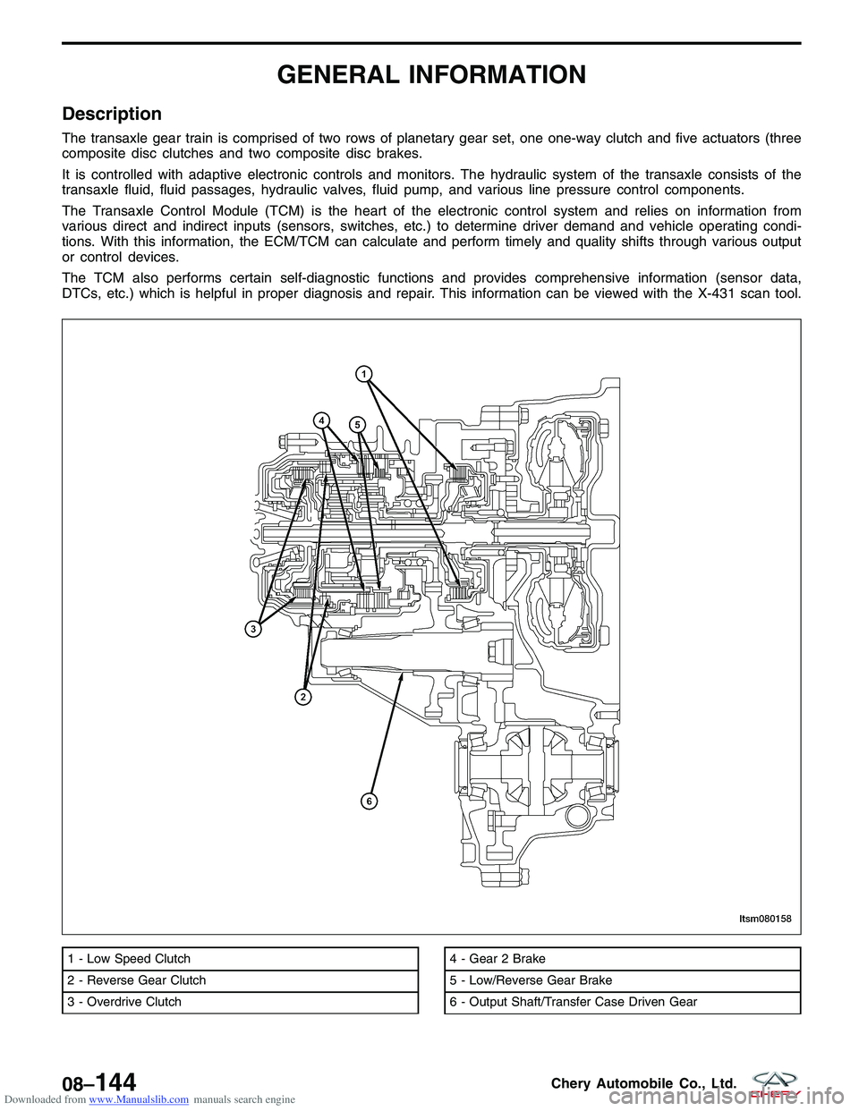
The transaxle gear train is comprised of two rows of planetary gear set, one one-way clutch and five actuators (three
composite disc clutches and two composite disc brakes.
It is controlled with adaptive electronic controls and monitors. The hydraulic system of the transaxle consists of the
transaxle fluid, fluid passages, hydraulic valves, fluid pump, and various line pressure control components.
The Transaxle Control Module (TCM) is the heart of the electronic control system and relies on information from
various direct and indirect inputs (sensors, switches, etc.) to determine driver demand and vehicle operating condi-
tions. With this information, the ECM/TCM can calculate and perform timely and quality shifts through various output
or control devices.
The TCM also performs certain self-diagnostic functions and provides comprehensive information (sensor data,
DTCs, etc.) which is helpful in proper diagnosis and repair. This information can be viewed with the X-431 scan tool.
1 - Low Speed Clutch
2 - Reverse Gear Clutch
3 - Overdrive Clutch4 - Gear 2 Brake
5 - Low/Reverse Gear Brake
6 - Output Shaft/Transfer Case Driven Gear
LTSM080158
08–144Chery Automobile Co., Ltd.
Page 1090 of 1903
Downloaded from www.Manualslib.com manuals search engine Specifications
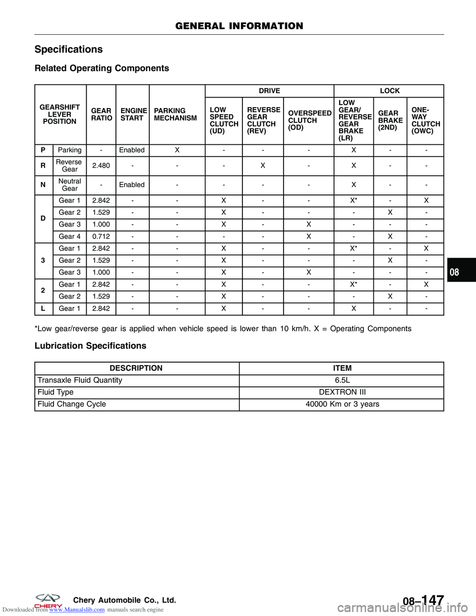
Related Operating Components
GEARSHIFTLEVER
POSITION GEAR
RATIO
ENGINE
START PARKING
MECHANISM DRIVE
LOCK
LOW
SPEED
CLUTCH
(UD) REVERSE
GEAR
CLUTCH
(REV)
OVERSPEED
CLUTCH
(OD) LOW
GEAR/
REVERSE
GEAR
BRAKE
(LR)GEAR
BRAKE
(2ND)
ONE-
WAY
CLUTCH
(OWC)
P Parking - Enabled X -- -X - -
R Reverse
Gear 2.480 -
--X -X - -
N Neutral
Gear - Enabled -
-- -X - -
D Gear 1 2.842 -
-X- -X* - X
Gear 2 1.529 - -X- -- X -
Gear 3 1.000 - -X- X - - -
Gear 4 0.712 - --- X - X -
3 Gear 1 2.842 -
-X- -X* - X
Gear 2 1.529 - -X- -- X -
Gear 3 1.000 - -X- X - - -
2 Gear 1 2.842 -
-X- -X* - X
Gear 2 1.529 - -X- -- X -
L Gear 1 2.842 - -X- -X - -
*Low gear/reverse gear is applied when vehicle speed is lower than 10 km/h. X = Operating Components
Lubrication Specifications
DESCRIPTION
ITEM
Transaxle Fluid Quantity 6.5L
Fluid Type DEXTRON III
Fluid Change Cycle 40000 Km or 3 years
GENERAL INFORMATION
08
08–147Chery Automobile Co., Ltd.
Page 1100 of 1903
Downloaded from www.Manualslib.com manuals search engine Transaxle Control Module (TCM) Connector Pin-Out Table
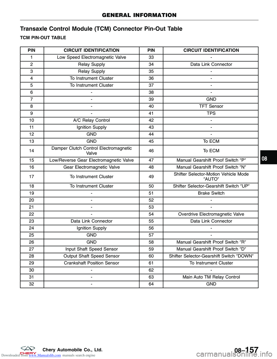
TCM PIN-OUT TABLE
PINCIRCUIT IDENTIFICATION PINCIRCUIT IDENTIFICATION
1 Low Speed Electromagnetic Valve 33 -
2 Relay Supply 34Data Link Connector
3 Relay Supply 35-
4 To Instrument Cluster 36-
5 To Instrument Cluster 37-
6 -38 -
7 -39GND
8 -40TFT Sensor
9 -41 TPS
10 A/C Relay Control 42-
11 Ignition Supply 43-
12 GND 44-
13 GND 45To ECM
14 Damper Clutch Control Electromagnetic
Valve 46
To ECM
15 Low/Reverse Gear Electromagnetic Valve 47 Manual Gearshift Proof Switch�P�
16 Gear Electromagnetic Valve 48Manual Gearshift Proof Switch �N�
17 To Instrument Cluster 49Shifter Selector-Motion Vehicle Mode
�AUTO�
18 To Instrument Cluster 50 Shifter Selector-Gearshift Switch �UP�
19 -51Brake Switch
20 -52 -
21 -53 -
22 -54Overdrive Electromagnetic Valve
23 Data Link Connector 55Data Link Connector
24 Ignition Supply 56-
25 GND 57-
26 GND 58Manual Gearshift Proof Switch �R�
27 Input Shaft Speed Sensor 59Manual Gearshift Proof Switch �D�
28 Output Shaft Speed Sensor 60 Shifter Selector-Gearshift Switch �DOWN�
29 Crankshaft Position Sensor 61To Instrument Cluster
30 -62 -
31 -63Main Auto TM Relay Control
32 -64GND
GENERAL INFORMATION
08
08–157Chery Automobile Co., Ltd.
Page 1102 of 1903
Downloaded from www.Manualslib.com manuals search engine Diagnostic Trouble Code (DTC) List
F4A4 Automatic Transaxle DTC List
DTCDTC DEFINITION
11 TPS Short Circuit
12 TPS Open Circuit
14 TPS Abnormal Adjustment
15 TFT Sensor Open Circuit
21 CKP Sensor Malfunction
22 Input Speed Sensor
23 Output Speed Sensor Fault
26 Brake Pedal Position Switch Circuit Malfunction
29 Vehicle Speed Sensor Malfunction
31 Reverse/Low Solenoid Malfunction
32 UD Solenoid Open
33 2 Gear Solenoid Open Circuit
34 Overdrive Solenoid Circuit Malfunction
36 Damper Clutch System Control Solenoid Malfunction
41 First Gear, Ration Out Of Limits
42 Second Gear, Ration Out Of Limits
43 Third Gear, Ration Out Of Limits
44 Fourth Gear, Ration Out Of Limits
46 Reverse Gear, Ration Out Of Limits
51 CAN Data Bus Interface Malfunction
52 DCC Digital Command System Malfunction
54 Electrical Relay Open Circuit
56 Neutral Indicator Lamp Open Circuit�
DIAGNOSIS & TESTING
08
08–159Chery Automobile Co., Ltd.
Page 1107 of 1903

Downloaded from www.Manualslib.com manuals search engine On Board Diagnostic Logic
•Self-diagnosis detection logic.
DTC NO. DTC DEFINITION DTC DETECTION
CONDITION DTC SET
CONDITION POSSIBLE CAUSES
22 Input speed sensor Vehicle is driving •
The Transaxle
Control Module
(TCM) will set this
DTC when the TCM
didn’t received pulse
signal from the input
shaft speed sensor
for above 1 seconds
when the vehicle is
driving for 30 km/h
at 3 or 4 gear.
• If the DTC was
set for 4 times, then
the A/T will be
locked in 3rd gear
(D gear) or shifted
to low gear when in
sports mode. •
Input shaft speed
sensor
• The retainer of
deceleration clutch
• Harness or
connectors (The
sensor circuit is open
or shorted)
• TCM
DTC Confirmation Procedure:
Before performing the following procedure, confirm that battery voltage is more than 12 V.
• Turn ignition switch off.
• Connect the X-431 scan tool to the Data Link Connector (DLC) - use the most current software available.
• Turn ignition switch on, with the scan tool, view and erase stored DTCs in the TCM.
• Start the engine and warm it to normal operating temperature.
• Drive the vehicle up to 10 km/h or more.
• With the scan tool, select view DTC and data stream.
• If the DTC is detected, the DTC condition is current. Go to Diagnostic Procedure - Step 1.
• If the DTC is not detected, the DTC condition is intermittent (See Diagnostic Help and Intermittent DTC Trou-
bleshooting in Section 08 Transaxle & Transfer Case for more information).
NOTE :
While performing electrical diagnosis & testing, always refer to the electrical schematics for specific circuit
and component information.
DIAGNOSIS & TESTING
08–164Chery Automobile Co., Ltd.
Page 1110 of 1903
Downloaded from www.Manualslib.com manuals search engine 6.CHECK INPUT SHAFT SPEED SENSOR SIGNAL
• Connect the TCM and sensor electrical connector.
• Start the vehicle and perform the following:
� Engine: 2000 RPM
� Vehicle: 50 km/h
� Gear: 3
• Check sensor signal between sensor terminal 2 and ground in the sensor electrical connector E-088 with the
X-431 or oscilloscope.
• Make sure the wave shape is normal and signal voltage is fluctuating from0-5V.
Is the check result normal?
Ye s>>Go to step 9.
No
>>Go to the next step.
7.CHECK INPUT SHAFT SPEED SENSOR
• Perform the following:
� Loosen the bolt of the sensor.
� Remove the sensor.
� Visually inspect the sensor for missing or chipped teeth.
Is the check result normal?
Ye s>>Replace the input speed sensor.
Monitor the input speed sensor signal on the X-431 or oscilloscope.
� If the input speed sensor signals were normal, the system is OK.
� If the input speed sensor signals were still irregular or missing, go to step 8.
No
>>Replace input speed sensor.
8.CHECK THE RETAINER OF DECELERATION CLUTCH
• Disassemble and inspect the A/T and replace the retainer for the deceleration clutch.
• Check for a chipped and damaged signal retainer for the deceleration clutch.
Is the check result normal?
Ye s>>Go to the next step.
No
>>Replace the retainer for the deceleration clutch.
Monitor the input speed sensor signal on the X-431 or oscilloscope.
If the signal pulse is not normal, repair the noise interference.
9.CHECK DTC
• With the X-431 scan tool, read TCM DTCs.
• Refer to �DTC Confirmation Procedure�.
Is the check result normal?
Ye s>>The system is now operating properly.
Reassemble the vehicle and road test to verify the customers complaint is repaired.
No
>>Replace the TCM.
DIAGNOSIS & TESTING
08
08–167Chery Automobile Co., Ltd.
Page 1122 of 1903
Downloaded from www.Manualslib.com manuals search engine Is the check result normal?
Ye s>>The condition that caused this DTC is intermittent (See Diagnostic Help in Section 08 Transaxle &
Transfer Case).
No
>>Go to the next step.
2.ACTUATE TEST
• With X-431, perform the solenoid actuate test.
• The solenoid should be heard.
Is the check result normal?
Ye s>>Go to step 7.
No
>>Go to the next step.
3.CHECK REVERSE/LOW GEAR ELECTRO-MAGNETIC VALVE
• Turn the ignition switch off.
• Disconnect A/T assembly connector.
NUMBER SOLENOID WIRE COLOR
1 Low Speed
Electro-Magnetic Valve (UD) White / Red
2 2nd Gear
Electro-Magnetic Valve (2nd) Yellow / Red
3 Damp clutch
system control
Electro-Magnetic Valve (DCC) Brown / Yellow
4 Overdrive
Electro-Magnetic Valve (OD) Blue / Yellow
5 Low/reverse
Gear Electro-
Magnetic Valve (L/R) Black / Red
DIAGNOSIS & TESTING
08
08–179Chery Automobile Co., Ltd.