2009 CHERY TIGGO engine oil
[x] Cancel search: engine oilPage 1333 of 1903
Downloaded from www.Manualslib.com manuals search engine Rear Stabilizer Bar Link
Removal & Installation
1. Raise and support the vehicle.
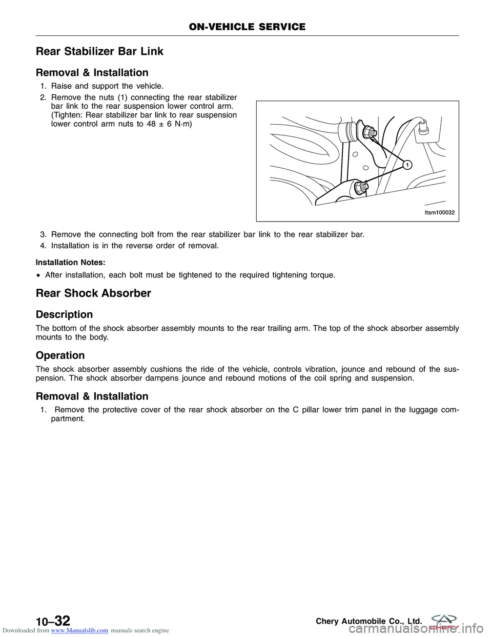
2. Remove the nuts (1) connecting the rear stabilizerbar link to the rear suspension lower control arm.
(Tighten: Rear stabilizer bar link to rear suspension
lower control arm nuts to 48 ± 6 N·m)
3. Remove the connecting bolt from the rear stabilizer bar link to the rear stabilizer bar.
4. Installation is in the reverse order of removal.
Installation Notes:
• After installation, each bolt must be tightened to the required tightening torque.
Rear Shock Absorber
Description
The bottom of the shock absorber assembly mounts to the rear trailing arm. The top of the shock absorber assembly
mounts to the body.
Operation
The shock absorber assembly cushions the ride of the vehicle, controls vibration, jounce and rebound of the sus-
pension. The shock absorber dampens jounce and rebound motions of the coil spring and suspension.
Removal & Installation
1. Remove the protective cover of the rear shock absorber on the C pillar lower trim panel in the luggage com-
partment.
ON-VEHICLE SERVICE
LTSM100032
10–32Chery Automobile Co., Ltd.
Page 1334 of 1903
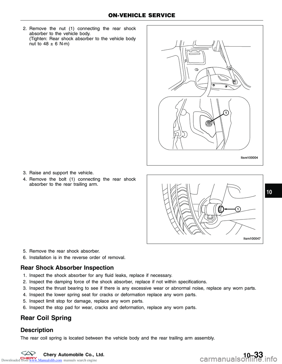
Downloaded from www.Manualslib.com manuals search engine 2. Remove the nut (1) connecting the rear shockabsorber to the vehicle body.
(Tighten: Rear shock absorber to the vehicle body
nut to 48 ± 6 N·m)
3. Raise and support the vehicle.
4. Remove the bolt (1) connecting the rear shock absorber to the rear trailing arm.
5. Remove the rear shock absorber.
6. Installation is in the reverse order of removal.
Rear Shock Absorber Inspection
1. Inspect the shock absorber for any fluid leaks, replace if necessary.
2. Inspect the damping force of the shock absorber, replace if not within specifications.
3. Inspect the thrust bearing to see if there is any excessive wear or abnormal noise, replace any worn parts.
4. Inspect the lower spring seat for cracks or deformation replace any worn parts.
5. Inspect limit stop for damage, replace any worn parts.
6. Inspect the stop pad for wear, cracks and deformation, replace any worn parts.
Rear Coil Spring
Description
The rear coil spring is located between the vehicle body and the rear trailing arm assembly.
ON-VEHICLE SERVICE
LTSM100004
LTSM100047
10
10–33Chery Automobile Co., Ltd.
Page 1335 of 1903
Downloaded from www.Manualslib.com manuals search engine Operation
Coil springs are designed to store energy and subsequently release it, and to absorb shock and maintain a force
between contacting surfaces. Coil springs are rated for specific vehicle applications.
Removal & Installation
1. Raise and support the vehicle.
2. Remove the wheel mounting nuts and the wheel assembly.(Tighten: Wheel mounting nuts to 110 N·m)
3. Use a jack to support the rear trailing arm.
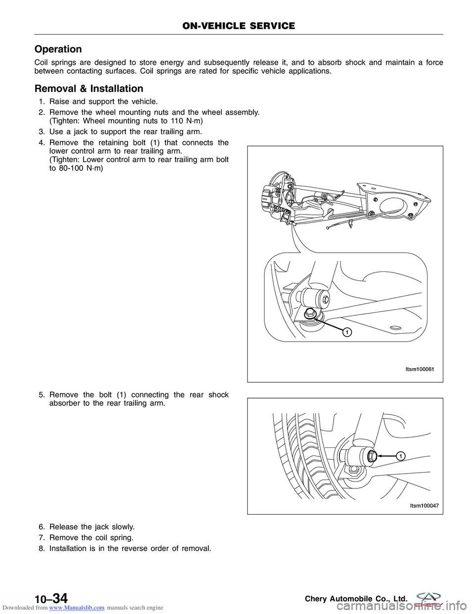
4. Remove the retaining bolt (1) that connects the lower control arm to rear trailing arm.
(Tighten: Lower control arm to rear trailing arm bolt
to 80-100 N·m)
5. Remove the bolt (1) connecting the rear shock absorber to the rear trailing arm.
6. Release the jack slowly.
7. Remove the coil spring.
8. Installation is in the reverse order of removal.
ON-VEHICLE SERVICE
LTSM100061
LTSM100047
10–34Chery Automobile Co., Ltd.
Page 1340 of 1903
Downloaded from www.Manualslib.com manuals search engine GENERAL INFORMATION
Description
Vehicle wheel alignment is the positioning of all interrelated front and rear suspension angles. These angles affect the
handling and steering of the vehicle when it is in motion. Proper wheel alignment is essential for efficient steering,
good directional stability, and proper tire wear.
The method of checking a vehicle’s front and rear wheel alignment varies depending on the manufacturer and type
of equipment used. The manufacturer’s instructions should always be followed to ensure accuracy of the alignment.
On this vehicle, the suspension angles that can be adjusted are as follows:
Front Axle
•Camber
• Caster
• Toe-in
Rear Axle
• Camber
• Toe-in
Check the wheel alignment and make all wheel alignment adjustments with the vehicle standing at its proper curb
height specification. Curb height is the normal riding height of the vehicle. It is measured from a certain point on the
vehicle to the ground or a designated area while the vehicle is sitting on a flat, level surface.
Operation
Curb Height Measurement
The wheel alignment is to be checked and all alignment adjustments made with the vehicle at its required curb height
specification.
• Vehicle height is to be checked with the vehicle on a flat, level surface, preferably a vehicle alignment rack.
• The tires are to be inflated to the recommended pressure.
• All tires are to be the same size as standard equipment.
• Vehicle height is checked with the fuel tank full of fuel, and no passenger or luggage compartment load.
• Vehicle height is not adjustable.
• If the measurement is not within specifications, inspect the vehicle for bent or weak suspension components.
• Compare the parts tag on the suspect coil spring(s) to the parts book and the vehicle sales code, checking for
a match.
• Once removed from the vehicle, compare the coil spring height to a new or known good coil spring. The
heights should vary if the suspect spring is weak.
NOTE :
Prior to reading the curb height measurement, the front and rear of the vehicle must be jounced to settle the sus-
pension. Induce jounce by pushing down on the center of the bumper (fascia), using care not to damage the vehicle,
moving the vehicle up and down, gradually increasing the suspension travel with each stroke. Release the bumper at
the bottom of each stroke, repeating this action several times. Perform this to both front and rear suspensions an
equal number of times.
Pre-Wheel Alignment Inspection
Before any attempt is made to change or correct the wheel alignment, the following inspection and necessary cor-
rections must be made to the vehicle to ensure proper alignment. 1. Verify the fuel tank is full of fuel. If the fuel tank is not full, the reduction in weight will affect the curb height of the vehicle and the alignment specifications.
2. The passenger and luggage compartments of the vehicle should be free of any load that is not factory equip- ment.
10
10–39Chery Automobile Co., Ltd.
Page 1398 of 1903
Downloaded from www.Manualslib.com manuals search engine Rear Disc Brake
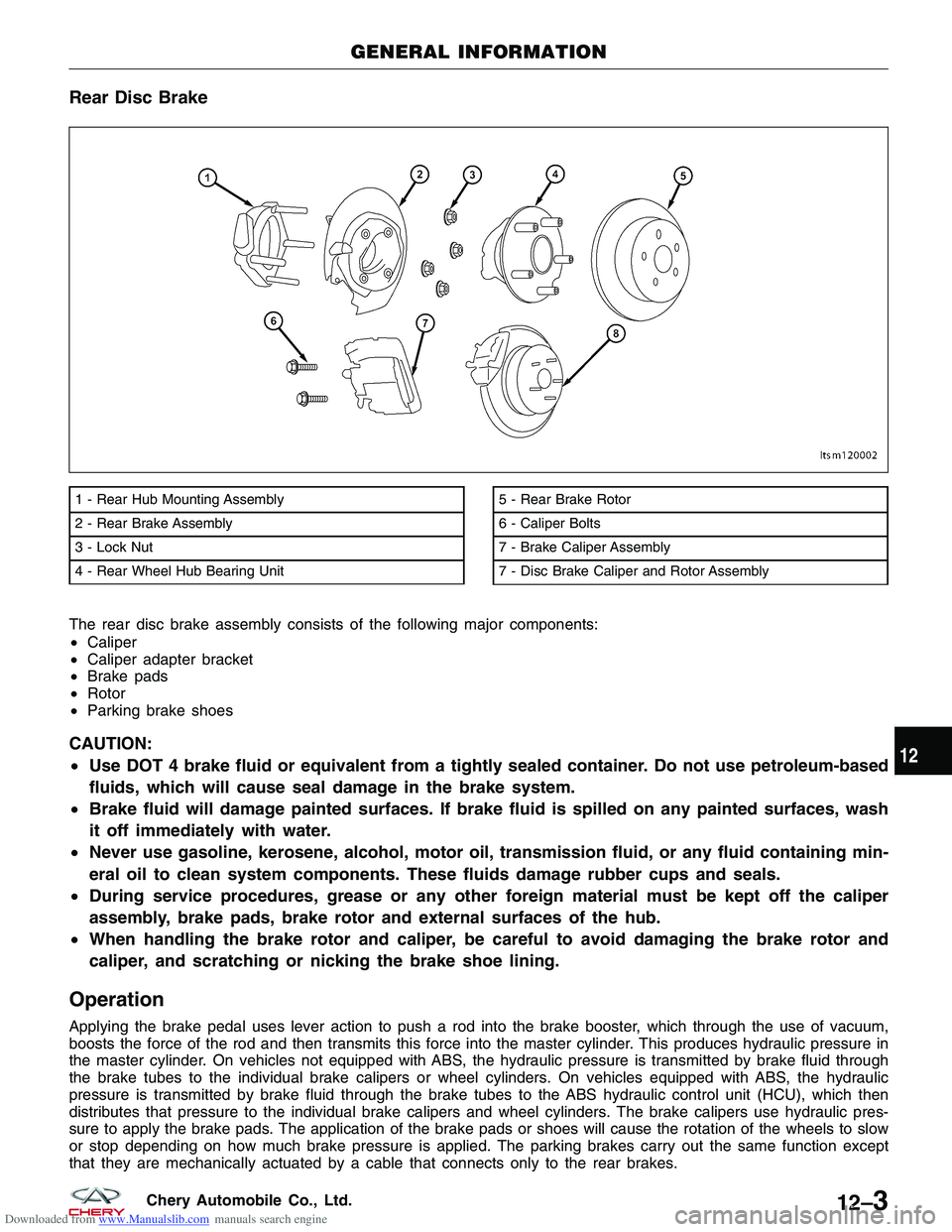
The rear disc brake assembly consists of the following major components:
•Caliper
• Caliper adapter bracket
• Brake pads
• Rotor
• Parking brake shoes
CAUTION:
•Use DOT 4 brake fluid or equivalent from a tightly sealed container. Do not use petroleum-based
fluids, which will cause seal damage in the brake system.
• Brake fluid will damage painted surfaces. If brake fluid is spilled on any painted surfaces, wash
it off immediately with water.
• Never use gasoline, kerosene, alcohol, motor oil, transmission fluid, or any fluid containing min-
eral oil to clean system components. These fluids damage rubber cups and seals.
• During service procedures, grease or any other foreign material must be kept off the caliper
assembly, brake pads, brake rotor and external surfaces of the hub.
• When handling the brake rotor and caliper, be careful to avoid damaging the brake rotor and
caliper, and scratching or nicking the brake shoe lining.
Operation
Applying the brake pedal uses lever action to push a rod into the brake booster, which through the use of vacuum,
boosts the force of the rod and then transmits this force into the master cylinder. This produces hydraulic pressure in
the master cylinder. On vehicles not equipped with ABS, the hydraulic pressure is transmitted by brake fluid through
the brake tubes to the individual brake calipers or wheel cylinders. On vehicles equipped with ABS, the hydraulic
pressure is transmitted by brake fluid through the brake tubes to the ABS hydraulic control unit (HCU), which then
distributes that pressure to the individual brake calipers and wheel cylinders. The brake calipers use hydraulic pres-
sure to apply the brake pads. The application of the brake pads or shoes will cause the rotation of the wheels to slow
or stop depending on how much brake pressure is applied. The parking brakes carry out the same function except
that they are mechanically actuated by a cable that connects only to the rear brakes.
1 - Rear Hub Mounting Assembly
2 - Rear Brake Assembly
3 - Lock Nut
4 - Rear Wheel Hub Bearing Unit5 - Rear Brake Rotor
6 - Caliper Bolts
7 - Brake Caliper Assembly
7 - Disc Brake Caliper and Rotor Assembly
GENERAL INFORMATION
LTSM120002
12
12–3Chery Automobile Co., Ltd.
Page 1494 of 1903
Downloaded from www.Manualslib.com manuals search engine DIAGNOSIS & TESTING
A/C System Performance
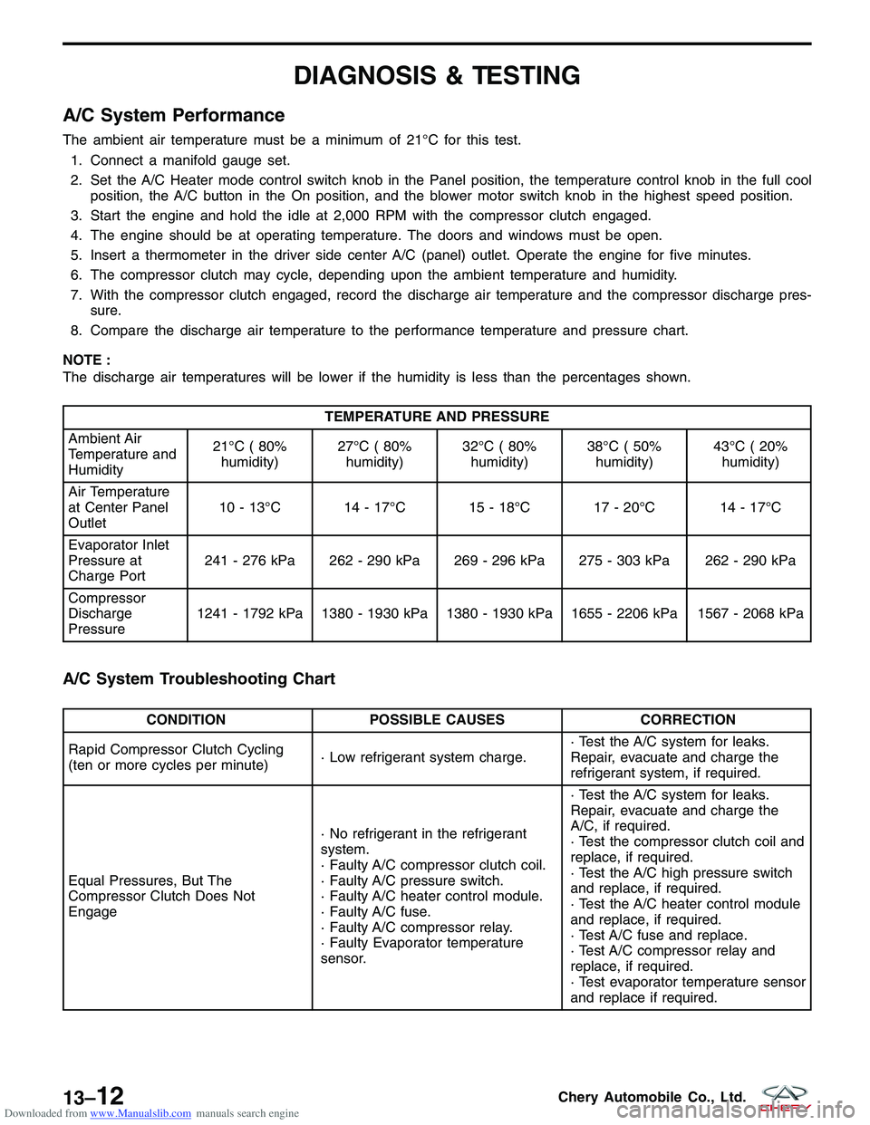
The ambient air temperature must be a minimum of 21°C for this test.1. Connect a manifold gauge set.
2. Set the A/C Heater mode control switch knob in the Panel position, the temperature control knob in the full cool position, the A/C button in the On position, and the blower motor switch knob in the highest speed position.
3. Start the engine and hold the idle at 2,000 RPM with the compressor clutch engaged.
4. The engine should be at operating temperature. The doors and windows must be open.
5. Insert a thermometer in the driver side center A/C (panel) outlet. Operate the engine for five minutes.
6. The compressor clutch may cycle, depending upon the ambient temperature and humidity.
7. With the compressor clutch engaged, record the discharge air temperature and the compressor discharge pres- sure.
8. Compare the discharge air temperature to the performance temperature and pressure chart.
NOTE :
The discharge air temperatures will be lower if the humidity is less than the percentages shown.
TEMPERATURE AND PRESSURE
Ambient Air
Temperature and
Humidity 21°C ( 80%
humidity) 27°C ( 80%
humidity) 32°C ( 80%
humidity) 38°C ( 50%
humidity) 43°C ( 20%
humidity)
Air Temperature
at Center Panel
Outlet 10 - 13°C 14 - 17°C 15 - 18°C 17 - 20°C 14 - 17°C
Evaporator Inlet
Pressure at
Charge Port 241 - 276 kPa 262 - 290 kPa 269 - 296 kPa 275 - 303 kPa 262 - 290 kPa
Compressor
Discharge
Pressure 1241 - 1792 kPa 1380 - 1930 kPa 1380 - 1930 kPa 1655 - 2206 kPa 1567 - 2068 kPa
A/C System Troubleshooting Chart
CONDITION
POSSIBLE CAUSES CORRECTION
Rapid Compressor Clutch Cycling
(ten or more cycles per minute) · Low refrigerant system charge.· Test the A/C system for leaks.
Repair, evacuate and charge the
refrigerant system, if required.
Equal Pressures, But The
Compressor Clutch Does Not
Engage · No refrigerant in the refrigerant
system.
· Faulty A/C compressor clutch coil.
· Faulty A/C pressure switch.
· Faulty A/C heater control module.
· Faulty A/C fuse.
· Faulty A/C compressor relay.
· Faulty Evaporator temperature
sensor.· Test the A/C system for leaks.
Repair, evacuate and charge the
A/C, if required.
· Test the compressor clutch coil and
replace, if required.
· Test the A/C high pressure switch
and replace, if required.
· Test the A/C heater control module
and replace, if required.
· Test A/C fuse and replace.
· Test A/C compressor relay and
replace, if required.
· Test evaporator temperature sensor
and replace if required.
13–12Chery Automobile Co., Ltd.
Page 1495 of 1903
Downloaded from www.Manualslib.com manuals search engine CONDITIONPOSSIBLE CAUSES CORRECTION
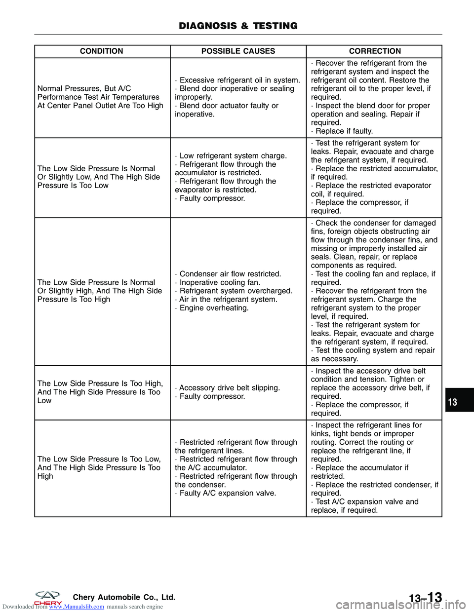
Normal Pressures, But A/C
Performance Test Air Temperatures
At Center Panel Outlet Are Too High · Excessive refrigerant oil in system.
· Blend door inoperative or sealing
improperly.
· Blend door actuator faulty or
inoperative.· Recover the refrigerant from the
refrigerant system and inspect the
refrigerant oil content. Restore the
refrigerant oil to the proper level, if
required.
· Inspect the blend door for proper
operation and sealing. Repair if
required.
· Replace if faulty.
The Low Side Pressure Is Normal
Or Slightly Low, And The High Side
Pressure Is Too Low · Low refrigerant system charge.
· Refrigerant flow through the
accumulator is restricted.
· Refrigerant flow through the
evaporator is restricted.
· Faulty compressor.· Test the refrigerant system for
leaks. Repair, evacuate and charge
the refrigerant system, if required.
· Replace the restricted accumulator,
if required.
· Replace the restricted evaporator
coil, if required.
· Replace the compressor, if
required.
The Low Side Pressure Is Normal
Or Slightly High, And The High Side
Pressure Is Too High · Condenser air flow restricted.
· Inoperative cooling fan.
· Refrigerant system overcharged.
· Air in the refrigerant system.
· Engine overheating.· Check the condenser for damaged
fins, foreign objects obstructing air
flow through the condenser fins, and
missing or improperly installed air
seals. Clean, repair, or replace
components as required.
· Test the cooling fan and replace, if
required.
· Recover the refrigerant from the
refrigerant system. Charge the
refrigerant system to the proper
level, if required.
· Test the refrigerant system for
leaks. Repair, evacuate and charge
the refrigerant system, if required.
· Test the cooling system and repair
as necessary.
The Low Side Pressure Is Too High,
And The High Side Pressure Is Too
Low · Accessory drive belt slipping.
· Faulty compressor.· Inspect the accessory drive belt
condition and tension. Tighten or
replace the accessory drive belt, if
required.
· Replace the compressor, if
required.
The Low Side Pressure Is Too Low,
And The High Side Pressure Is Too
High · Restricted refrigerant flow through
the refrigerant lines.
· Restricted refrigerant flow through
the A/C accumulator.
· Restricted refrigerant flow through
the condenser.
· Faulty A/C expansion valve.· Inspect the refrigerant lines for
kinks, tight bends or improper
routing. Correct the routing or
replace the refrigerant line, if
required.
· Replace the accumulator if
restricted.
· Replace the restricted condenser, if
required.
· Test A/C expansion valve and
replace, if required.
DIAGNOSIS & TESTING
13
13–13Chery Automobile Co., Ltd.
Page 1512 of 1903
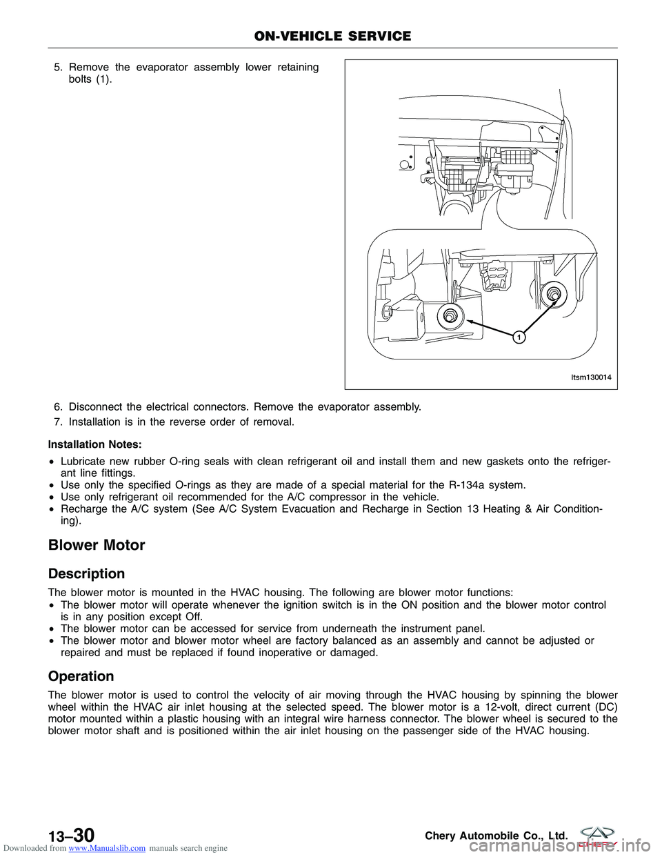
Downloaded from www.Manualslib.com manuals search engine 5. Remove the evaporator assembly lower retainingbolts (1).
6. Disconnect the electrical connectors. Remove the evaporator assembly.
7. Installation is in the reverse order of removal.
Installation Notes:
• Lubricate new rubber O-ring seals with clean refrigerant oil and install them and new gaskets onto the refriger-
ant line fittings.
• Use only the specified O-rings as they are made of a special material for the R-134a system.
• Use only refrigerant oil recommended for the A/C compressor in the vehicle.
• Recharge the A/C system (See A/C System Evacuation and Recharge in Section 13 Heating & Air Condition-
ing).
Blower Motor
Description
The blower motor is mounted in the HVAC housing. The following are blower motor functions:
•The blower motor will operate whenever the ignition switch is in the ON position and the blower motor control
is in any position except Off.
• The blower motor can be accessed for service from underneath the instrument panel.
• The blower motor and blower motor wheel are factory balanced as an assembly and cannot be adjusted or
repaired and must be replaced if found inoperative or damaged.
Operation
The blower motor is used to control the velocity of air moving through the HVAC housing by spinning the blower
wheel within the HVAC air inlet housing at the selected speed. The blower motor is a 12-volt, direct current (DC)
motor mounted within a plastic housing with an integral wire harness connector. The blower wheel is secured to the
blower motor shaft and is positioned within the air inlet housing on the passenger side of the HVAC housing.
ON-VEHICLE SERVICE
LTSM130014
13–30Chery Automobile Co., Ltd.