Page 1696 of 1903
Downloaded from www.Manualslib.com manuals search engine Immobilizer Control Module Connector Pin-Out Table
PINCIRCUIT IDENTIFICATION PINCIRCUIT IDENTIFICATION
1 Continuous Supply Voltage 7Diagnostic Link K
2 GND 8W-Line
3 -9Coil (GND)
4 Ignition Switch 10Coil (ANT B)
5 R-Line 11Coil (ANT A)
6-—-
IMMOBILIZER CONTROL MODULE
15–11 2Chery Automobile Co., Ltd.
Page 1704 of 1903

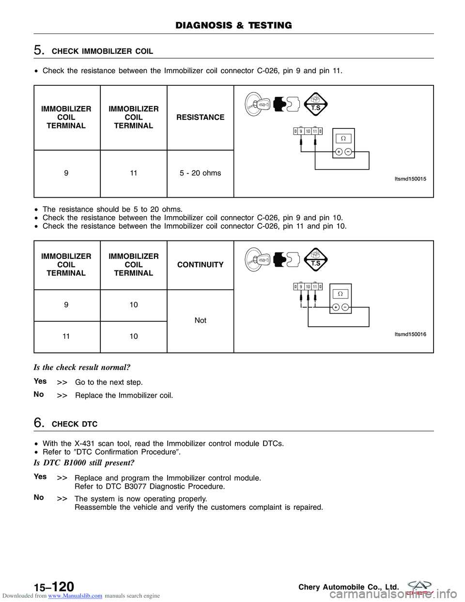
Downloaded from www.Manualslib.com manuals search engine 5.CHECK IMMOBILIZER COIL
• Check the resistance between the Immobilizer coil connector C-026, pin 9 and pin 11.
IMMOBILIZER
COIL
TERMINAL IMMOBILIZER
COIL
TERMINAL RESISTANCE
9
115 - 20 ohms
• The resistance should be 5 to 20 ohms.
• Check the resistance between the Immobilizer coil connector C-026, pin 9 and pin 10.
• Check the resistance between the Immobilizer coil connector C-026, pin 11 and pin 10.
IMMOBILIZER
COIL
TERMINAL IMMOBILIZER
COIL
TERMINAL CONTINUITY
91
0
Not
11 1 0
Is the check result normal?
Ye s>>Go to the next step.
No
>>Replace the Immobilizer coil.
6.CHECK DTC
• With the X-431 scan tool, read the Immobilizer control module DTCs.
• Refer to �DTC Confirmation Procedure�.
Is DTC B1000 still present?
Ye s>>Replace and program the Immobilizer control module.
Refer to DTC B3077 Diagnostic Procedure.
No
>>The system is now operating properly.
Reassemble the vehicle and verify the customers complaint is repaired.
DIAGNOSIS & TESTING
15–120Chery Automobile Co., Ltd.
Page 1718 of 1903
Downloaded from www.Manualslib.com manuals search engine 3.CHECK IMMOBILIZER CONTROL MODULE ELECTRICAL CONNECTOR
• Turn ignition switch off.
• Disconnect the Immobilizer control module electrical
connectors C-026 (1).
• Inspect the electrical connector for damage.
Is the electrical connector OK?
Ye s>>Go to the next step.
No
>>Repair or replace the electrical connector
as necessary.
4.CHECK IMMOBILIZER COIL
• Check the resistance of the Immobilizer coil between the Immobilizer coil connector C-026, pin 9 and pin 11.
IMMOBILIZER COIL
TERMINAL IMMOBILIZER COIL
TERMINAL
91 1
Is the resistance range from 5 to 20 ohms?
Ye s>>Go to the next step.
No
>>Replace the Immobilizer coil.
DIAGNOSIS & TESTING
LTSMD150019
15–134Chery Automobile Co., Ltd.
Page 1719 of 1903
Downloaded from www.Manualslib.com manuals search engine 5.CHECK IMMOBILIZER COIL
• Check the resistance of the Immobilizer coil between the Immobilizer coil connector C-026, pin 9 and pin 10.
• Check the resistance of the Immobilizer coil between the Immobilizer coil connector C-026, pin 11 and pin 10.
IMMOBILIZER
COIL
TERMINAL IMMOBILIZER
COIL
TERMINAL CONTINUITY
91
0
Not
11 1 0
• Continuity should not exist.
Is the check result normal?
Ye s>>Go to the next step.
No
>>Replace the Immobilizer coil.
6.REPLACE AND PROGRAM TRANSPONDER
• Reconnect the Immobilizer control module electrical
connector C-026.
• Replace the chip (1) with a new one.
DIAGNOSIS & TESTING
VISMD150018
15
15–135Chery Automobile Co., Ltd.
Page 1725 of 1903
Downloaded from www.Manualslib.com manuals search engine 4.CHECK THE IMMOBILIZER COIL
• Check the resistance of the Immobilizer coil between the Immobilizer coil connector C-026, pin 9 and pin 11.
IMMOBILIZER COIL
TERMINAL IMMOBILIZER COIL
TERMINAL
91 1
Is the resistance range from 5 to 20 ohms?
Ye s>>Go to the next step.
No
>>Replace the Immobilizer coil.
5.CHECK IMMOBILIZER COIL
• Check the resistance between the Immobilizer coil connector C-026, pin 9 and pin 10.
• Check the resistance between the Immobilizer coil connector C-026, pin 11 and pin 10.
IMMOBILIZER
COIL
TERMINAL IMMOBILIZER
COIL
TERMINAL CONTINUITY
91
0
Not
11 1 0
Is the check result normal?
Ye s>>Go to the next step.
No
>>Replace the Immobilizer coil.
DIAGNOSIS & TESTING
15
15–141Chery Automobile Co., Ltd.
Page 1875 of 1903

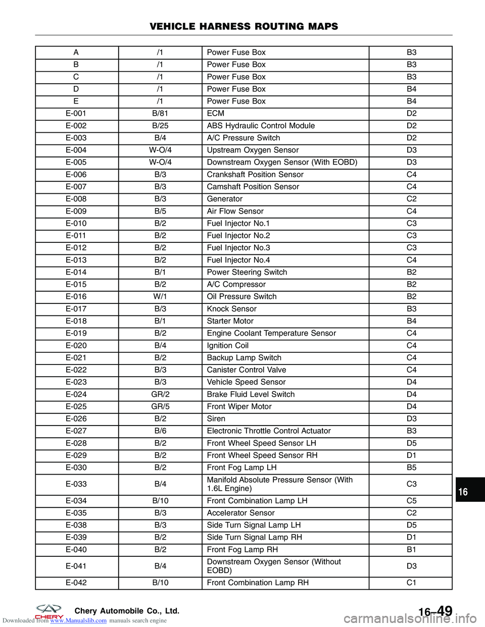
Downloaded from www.Manualslib.com manuals search engine A/1Power Fuse Box B3
B /1Power Fuse Box B3
C /1Power Fuse Box B3
D /1Power Fuse Box B4
E /1Power Fuse Box B4
E-001 B/81 ECM D2
E-002 B/25 ABS Hydraulic Control Module D2
E-003 B/4A/C Pressure Switch D2
E-004 W-O/4 Upstream Oxygen Sensor D3
E-005 W-O/4 Downstream Oxygen Sensor (With EOBD) D3
E-006 B/3Crankshaft Position Sensor C4
E-007 B/3Camshaft Position Sensor C4
E-008 B/3Generator C2
E-009 B/5Air Flow Sensor C4
E-010 B/2Fuel Injector No.1 C3
E-011 B/2Fuel Injector No.2 C3
E-012 B/2Fuel Injector No.3 C3
E-013 B/2Fuel Injector No.4 C4
E-014 B/1Power Steering Switch B2
E-015 B/2A/C Compressor B2
E-016 W/1 Oil Pressure Switch B2
E-017 B/3Knock Sensor B3
E-018 B/1Starter Motor B4
E-019 B/2Engine Coolant Temperature Sensor C4
E-020 B/4Ignition Coil C4
E-021 B/2Backup Lamp Switch C4
E-022 B/3Canister Control Valve C4
E-023 B/3Vehicle Speed Sensor D4
E-024 GR/2 Brake Fluid Level Switch D4
E-025 GR/5 Front Wiper Motor D4
E-026 B/2Siren D3
E-027 B/6Electronic Throttle Control Actuator B3
E-028 B/2Front Wheel Speed Sensor LH D5
E-029 B/2Front Wheel Speed Sensor RH D1
E-030 B/2Front Fog Lamp LH B5
E-033 B/4Manifold Absolute Pressure Sensor (With
1.6L Engine) C3
E-034 B/10 Front Combination Lamp LH C5
E-035 B/3Accelerator Sensor C2
E-038 B/3Side Turn Signal Lamp LH D5
E-039 B/2Side Turn Signal Lamp RH D1
E-040 B/2Front Fog Lamp RH B1
E-041 B/4Downstream Oxygen Sensor (Without
EOBD) D3
E-042 B/10 Front Combination Lamp RH C1
VEHICLE HARNESS ROUTING MAPS
16
16–49Chery Automobile Co., Ltd.
Page 1878 of 1903

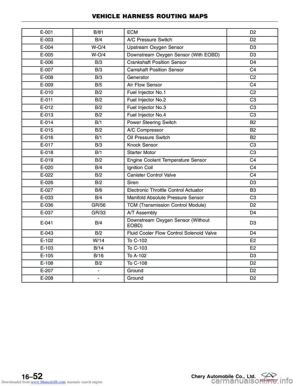
Downloaded from www.Manualslib.com manuals search engine E-001B/81 ECM D2
E-003 B/4A/C Pressure Switch D2
E-004 W-O/4 Upstream Oxygen Sensor D3
E-005 W-O/4 Downstream Oxygen Sensor (With EOBD) D3
E-006 B/3Crankshaft Position Sensor D4
E-007 B/3Camshaft Position Sensor C4
E-008 B/3Generator C2
E-009 B/5Air Flow Sensor C4
E-010 B/2Fuel Injector No.1 C2
E-011 B/2Fuel Injector No.2 C3
E-012 B/2Fuel Injector No.3 C3
E-013 B/2Fuel Injector No.4 C3
E-014 B/1Power Steering Switch B2
E-015 B/2A/C Compressor B2
E-016 B/1Oil Pressure Switch B2
E-017 B/3Knock Sensor C3
E-018 B/1Starter Motor C3
E-019 B/2Engine Coolant Temperature Sensor C4
E-020 B/4Ignition Coil C4
E-022 B/2Canister Control Valve C4
E-026 B/2Siren D3
E-027 B/6Electronic Throttle Control Actuator B3
E-033 B/4Manifold Absolute Pressure Sensor C3
E-036 GR/56 TCM (Transmission Control Module) D2
E-037 GR/33 A/T Assembly D4
E-041 B/4Downstream Oxygen Sensor (Without
EOBD) D3
E-043 B/2Fluid Cooler Flow Control Solenoid Valve D4
E-102 W/14 To C-102 E2
E-103 B/14 To C-103 E2
E-105 B/16 To A-102 D3
E-108 B/2To C-108 D2
E-207 -Ground D2
E-208 -Ground D2
VEHICLE HARNESS ROUTING MAPS
16–52Chery Automobile Co., Ltd.
Page 1880 of 1903

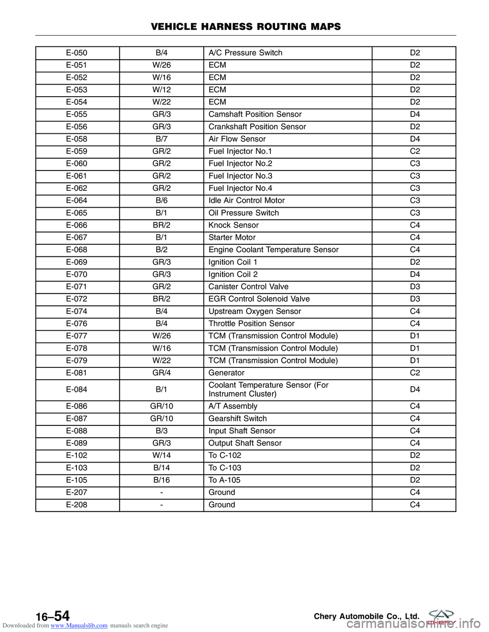
Downloaded from www.Manualslib.com manuals search engine E-050B/4A/C Pressure Switch D2
E-051 W/26 ECM D2
E-052 W/16 ECM D2
E-053 W/12 ECM D2
E-054 W/22 ECM D2
E-055 GR/3 Camshaft Position Sensor D4
E-056 GR/3 Crankshaft Position Sensor D2
E-058 B/7Air Flow Sensor D4
E-059 GR/2 Fuel Injector No.1 C2
E-060 GR/2 Fuel Injector No.2 C3
E-061 GR/2 Fuel Injector No.3 C3
E-062 GR/2 Fuel Injector No.4 C3
E-064 B/6Idle Air Control Motor C3
E-065 B/1Oil Pressure Switch C3
E-066 BR/2 Knock Sensor C4
E-067 B/1Starter Motor C4
E-068 B/2Engine Coolant Temperature Sensor C4
E-069 GR/3 Ignition Coil 1 D2
E-070 GR/3 Ignition Coil 2 D4
E-071 GR/2 Canister Control Valve D3
E-072 BR/2 EGR Control Solenoid Valve D3
E-074 B/4Upstream Oxygen Sensor C4
E-076 B/4Throttle Position Sensor C4
E-077 W/26 TCM (Transmission Control Module) D1
E-078 W/16 TCM (Transmission Control Module) D1
E-079 W/22 TCM (Transmission Control Module) D1
E-081 GR/4 Generator C2
E-084 B/1Coolant Temperature Sensor (For
Instrument Cluster) D4
E-086 GR/10 A/T Assembly C4
E-087 GR/10 Gearshift Switch C4
E-088 B/3Input Shaft Sensor C4
E-089 GR/3 Output Shaft Sensor C4
E-102 W/14 To C-102 D2
E-103 B/14 To C-103 D2
E-105 B/16 To A-105 D2
E-207 -Ground C4
E-208 -Ground C4
VEHICLE HARNESS ROUTING MAPS
16–54Chery Automobile Co., Ltd.