2009 CHERY TIGGO belt
[x] Cancel search: beltPage 1603 of 1903
Downloaded from www.Manualslib.com manuals search engine CHIME
Description
The chime is located in the Instrument Cluster (IC). The chime warning system is an audible notification to the driver.
The chime warning system is designed to alert the driver of a vehicle problem or condition.
Operation
The Instrument Cluster (IC) uses hard wired inputs from various sensors and switches to activate the chime. The
sensors and switches are located throughout the vehicle. The following conditions will cause the chime to operate:
•Turn signal on
• Hazard warning flashers on
• Seat belt unbuckled
• Low fuel level
• Low oil pressure
• Low brake fluid level
• Doors unlocked
CHIME
15
15–19Chery Automobile Co., Ltd.
Page 1622 of 1903
Downloaded from www.Manualslib.com manuals search engine BODY CONTROL MODULE - BCM
Description
The Body Control Module (BCM) is located behind the glove box. The BCM controls many electrical components and
systems for the vehicle electrical system. The BCM is the primary hub that controls functions such as internal and
external lighting, power windows and power door locks.
Operation
The Body Control Module (BCM) uses hard wired inputs from various sensors and switches. The sensors and
switches are located throughout the vehicle.
The following components are inputs to the BCM:
•Key switch
• Rear defroster switch
• Hazard lamp switch
• Power window switches
• Power door lock switches
• Seat belt switch
• Vehicle speed
• Door ajar switches
• Turn signal switch
The following components are outputs from the BCM:
• Key lamp
• Stop lamp relay
• Rear defroster grid
• Courtesy lamps
• Power window motor
• Power door lock motor
• Turn signal lamps
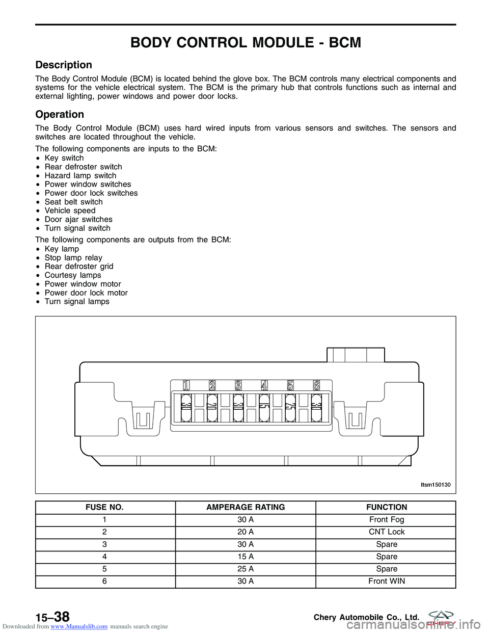
FUSE NO. AMPERAGE RATING FUNCTION
1 30 AFront Fog
2 20 ACNT Lock
3 30 A Spare
4 15 A Spare
5 25 A Spare
6 30 AFront WIN
LTSM150130
15–38Chery Automobile Co., Ltd.
Page 1636 of 1903
Downloaded from www.Manualslib.com manuals search engine INSTRUMENT CLUSTER
Description
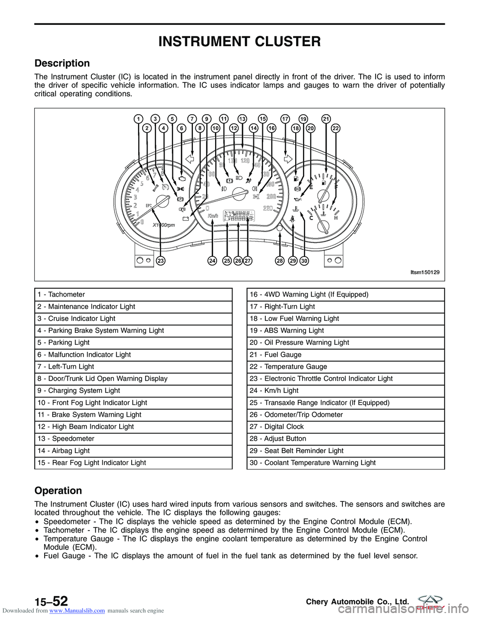
The Instrument Cluster (IC) is located in the instrument panel directly in front of the driver. The IC is used to inform
the driver of specific vehicle information. The IC uses indicator lamps and gauges to warn the driver of potentially
critical operating conditions.
Operation
The Instrument Cluster (IC) uses hard wired inputs from various sensors and switches. The sensors and switches are
located throughout the vehicle. The IC displays the following gauges:
•Speedometer - The IC displays the vehicle speed as determined by the Engine Control Module (ECM).
• Tachometer - The IC displays the engine speed as determined by the Engine Control Module (ECM).
• Temperature Gauge - The IC displays the engine coolant temperature as determined by the Engine Control
Module (ECM).
• Fuel Gauge - The IC displays the amount of fuel in the fuel tank as determined by the fuel level sensor.
1 - Tachometer
2 - Maintenance Indicator Light
3 - Cruise Indicator Light
4 - Parking Brake System Warning Light
5 - Parking Light
6 - Malfunction Indicator Light
7 - Left-Turn Light
8 - Door/Trunk Lid Open Warning Display
9 - Charging System Light
10 - Front Fog Light Indicator Light
11 - Brake System Warning Light
12 - High Beam Indicator Light
13 - Speedometer
14 - Airbag Light
15 - Rear Fog Light Indicator Light16 - 4WD Warning Light (If Equipped)
17 - Right-Turn Light
18 - Low Fuel Warning Light
19 - ABS Warning Light
20 - Oil Pressure Warning Light
21 - Fuel Gauge
22 - Temperature Gauge
23 - Electronic Throttle Control Indicator Light
24 - Km/h Light
25 - Transaxle Range Indicator (If Equipped)
26 - Odometer/Trip Odometer
27 - Digital Clock
28 - Adjust Button
29 - Seat Belt Reminder Light
30 - Coolant Temperature Warning Light
LTSM150129
15–52Chery Automobile Co., Ltd.
Page 1646 of 1903
Downloaded from www.Manualslib.com manuals search engine Instrument Cluster Connector Pin-Out Table
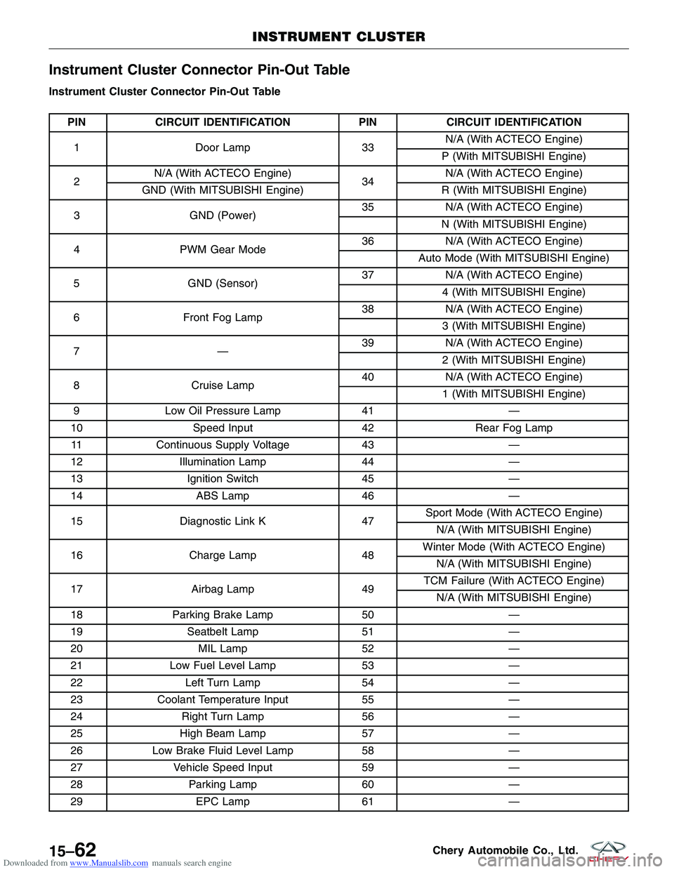
Instrument Cluster Connector Pin-Out Table
PINCIRCUIT IDENTIFICATION PINCIRCUIT IDENTIFICATION
1 Door Lamp 33N/A (With ACTECO Engine)
P (With MITSUBISHI Engine)
2 N/A (With ACTECO Engine)
34N/A (With ACTECO Engine)
GND (With MITSUBISHI Engine) R (With MITSUBISHI Engine)
3 GND (Power) 35
N/A (With ACTECO Engine)
N (With MITSUBISHI Engine)
4 PWM Gear Mode 36
N/A (With ACTECO Engine)
Auto Mode (With MITSUBISHI Engine)
5 GND (Sensor) 37
N/A (With ACTECO Engine)
4 (With MITSUBISHI Engine)
6 Front Fog Lamp 38
N/A (With ACTECO Engine)
3 (With MITSUBISHI Engine)
7— 39
N/A (With ACTECO Engine)
2 (With MITSUBISHI Engine)
8 Cruise Lamp 40
N/A (With ACTECO Engine)
1 (With MITSUBISHI Engine)
9 Low Oil Pressure Lamp 41—
10 Speed Input 42Rear Fog Lamp
11 Continuous Supply Voltage 43—
12 Illumination Lamp 44—
13 Ignition Switch 45—
14 ABS Lamp 46—
15 Diagnostic Link K 47Sport Mode (With ACTECO Engine)
N/A (With MITSUBISHI Engine)
16 Charge Lamp 48Winter Mode (With ACTECO Engine)
N/A (With MITSUBISHI Engine)
17 Airbag Lamp 49TCM Failure (With ACTECO Engine)
N/A (With MITSUBISHI Engine)
18 Parking Brake Lamp 50—
19 Seatbelt Lamp 51—
20 MIL Lamp 52—
21 Low Fuel Level Lamp 53—
22 Left Turn Lamp 54—
23 Coolant Temperature Input 55—
24 Right Turn Lamp 56—
25 High Beam Lamp 57—
26 Low Brake Fluid Level Lamp 58—
27 Vehicle Speed Input 59—
28 Parking Lamp 60—
29 EPC Lamp 61—
INSTRUMENT CLUSTER
15–62Chery Automobile Co., Ltd.
Page 1895 of 1903

Downloaded from www.Manualslib.com manuals search engine Restraints Harness
J-001W/25Restraints Control Module
J-002 G/2Front Passenger Airbag
J-003 G/2Driver Airbag
J-005 B/2Spiral Cable
J-006 W/2Driver Seatbelt Pre-Tensioner
J-007 G/2Passenger Seatbelt Pre-Tensioner
J-100 W/6To C-106
J-201 -Ground
VEHICLE HARNESS ROUTING MAPS
LTSMW170017T
16
16–69Chery Automobile Co., Ltd.
Page 1896 of 1903

Downloaded from www.Manualslib.com manuals search engine A
A-Pillar Trim Panel, Body Interior................15-11
A/C System Evacuation and Recharge, System Plumbing ......................... 13-37
Accelerator Pedal Position (APP) Sensor, 2.0L Engine Controls .......................... 3-438
Accelerator Pedal Position Sensor, 1.6L & 1.8L Engine Controls .......................... 3-224
Accelerator Sensor, 1.6L & 1.8L Engine Controls .....3-221
Accelerator Sensor, 2.0L Engine Controls ..........3-432
Accessory Drive Belt, 1.6L & 1.8L Engine Mechanical . . 2-17
Accessory Drive Belt, 2.0L Engine Mechanical ........2-91
Accessory Drive Belt, 2.4L Engine Mechanical .......2-167
Accumulator, System Plumbing .................13-43
Air Cleaner Element, 1.6L & 1.8L Engine Mechanical . . . 2-18
Air Cleaner Element, 2.0L Engine Mechanical .........2-92
Air Cleaner Element, 2.4L Engine Mechanical ........2-168
Air Cleaner Housing, 1.6L & 1.8L Engine Mechanical . . . 2-18
Air Cleaner Housing, 2.0L Engine Mechanical ........2-93
Air Cleaner Housing, 2.4L Engine Mechanical .......2-169
Air Distribution ............................ 13-25
Air Flow Sensor - 1.8L, 1.6L & 1.8L Engine Controls . . 3-223
Air Flow Sensor, 2.0L Engine Controls ............3-431
Air Flow Sensor, 2.4L Engine Controls ............3-537
Airbag System ............................. 14-1
Airbag System Disarming Procedure, Airbag System . . . 14-46
Alignment ................................ 10-38
Antenna, Body Interior ....................... 15-10
Antilock Brake System (ABS) Bleeding Procedure, Antilock Brakes .......................... 12-76
Antilock Brake System (ABS) Hydraulic Control Module, Antilock Brakes .......................... 12-77
Antilock Brakes ............................ 12-34
Assist Handle, Body Interior ...................15-13
Audio System, Body Interior ....................15-4
Automatic Shifter Selector, DP0 Automatic Transaxle . . . 8-140
Automatic Shifter Selector, F4A4 Automatic Transaxle . . 8-243
B
B-Pillar Lower Trim Panel, Body Interior ...........15-11
B-Pillar Upper Trim Panel, Body Interior ...........15-12
Back Cargo Door, Body Exterior ................15-175
Base Brakes ............................... 12-1
Battery Hold Down, Starting System ...............5-8
Battery Tray, Starting System ....................5-9
Battery, Starting System ........................5-7
Bleeding Hydraulic Clutch, Clutch System ..........8-325Blower Motor Resistor, Manual Temperature Control . . . 13-16
Blower Motor, Air Distribution
..................13-30
Body Control Module (BCM), Body Interior .........15-44
Body Control Module - BCM, Body Interior .........15-38
Body Dimensions, Body Exterior ................15-147
Body Exterior ............................ 15-145
Body Fuse and Relay Box, Vehicle Fuse Box Information .......................... 16-42
Body Interior .............................. 15-1
Body Interior Trim, Body Interior ................15-11
Body, Body Exterior ........................ 15-157
Brake Bleeding, Base Brakes ....................12-9
Bumpers, Body Exterior ..................... 15-166
C
C-Pillar Lower Trim Panel, Body Interior ...........15-12
C-Pillar Upper Trim Panel, Body Interior ...........15-13
Camshaft Position (CMP) Sensor, 1.6L & 1.8L Engine Controls .......................... 3-220
Camshaft Position (CMP) Sensor, 2.0L Engine Controls ............................... 3-431
Camshaft Position (CMP) Sensor, 2.4L Engine Controls ............................... 3-536
Camshaft, 1.6L & 1.8L Engine Mechanical ......2-20, 2-66
Camshaft, 2.0L Engine Mechanical ...........2-139, 2-94
Camshaft, 2.4L Engine Mechanical ..........2-171, 2-243
CAN Vehicle Communications, Body Interior ........15-16
Canister Control Solenoid Valve 2.4L, Evaporative Emissions ...................... 3-584
Canister Control Valve 1.6L & 1.8L & 2.0L, Evaporative Emissions ...................... 3-584
Catalytic Converter, Exhaust System ................7-6
Charging System ............................ 5-11
Chime, Body Interior ........................ 15-19
Clutch and Pressure Plate, Clutch System ..........8-319
Clutch Assembly Service, Clutch System ...........8-319
Clutch Master Cylinder, Clutch System ............8-322
Clutch Slave Cylinder, Clutch System .............8-324
Clutch System ............................. 8-316
Compressor, System Plumbing .................13-39
Condenser, System Plumbing ..................13-42
Connecting Rods, 1.6L & 1.8L Engine Mechanical .....2-58
Connecting Rods, 2.0L Engine Mechanical ..........2-131
Connecting Rods, 2.4L Engine Mechanical ..........2-229
Coolant Pump, Cooling System ..................6-16
Coolant Temperature Sensor (For Instrument Cluster), 2.4L Engine Controls ....................... 3-532
Cooling Fan, Cooling System ...................6-18
INDEX
AI
AI-1
Page 1898 of 1903
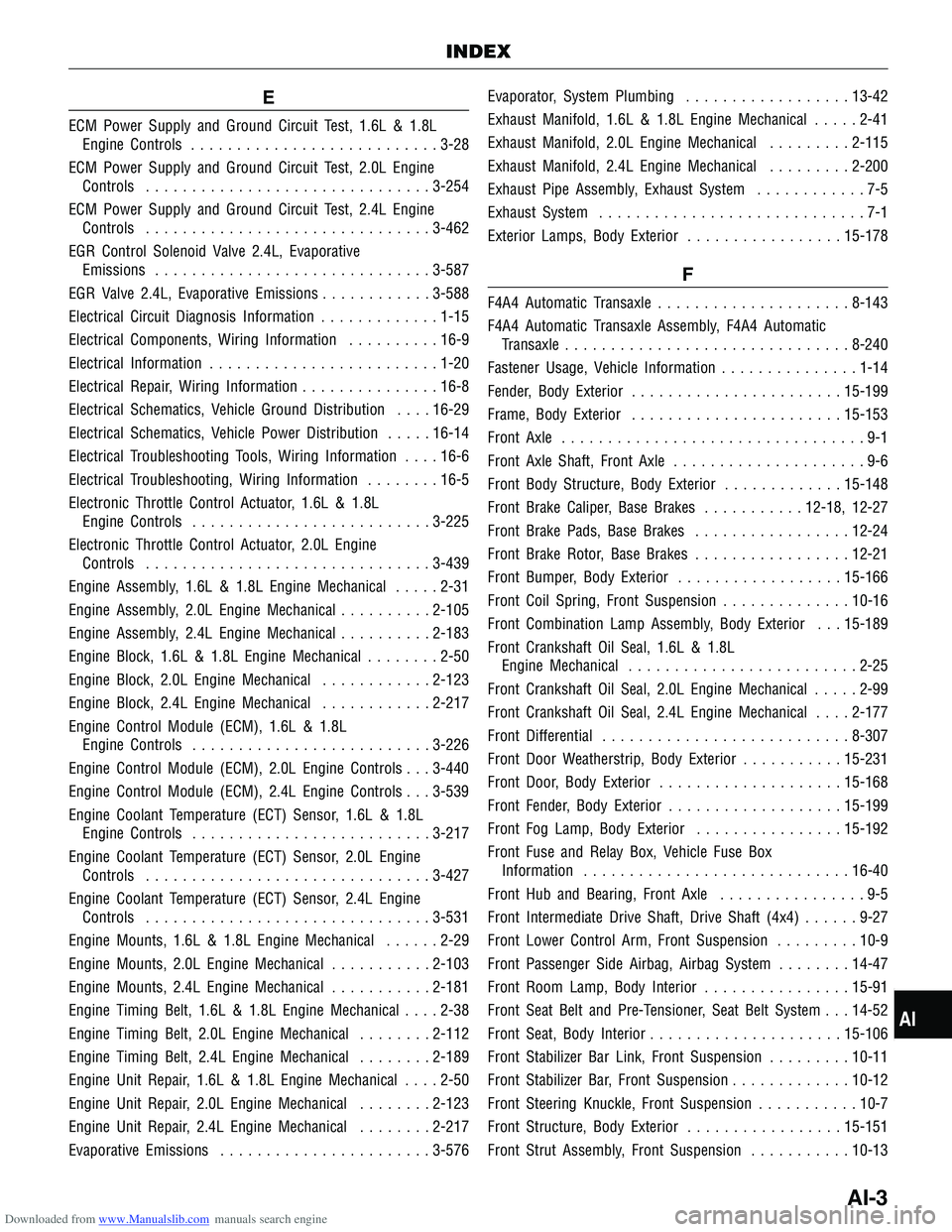
Downloaded from www.Manualslib.com manuals search engine E
ECM Power Supply and Ground Circuit Test, 1.6L & 1.8LEngine Controls ........................... 3-28
ECM Power Supply and Ground Circuit Test, 2.0L Engine Controls ............................... 3-254
ECM Power Supply and Ground Circuit Test, 2.4L Engine Controls ............................... 3-462
EGR Control Solenoid Valve 2.4L, Evaporative Emissions .............................. 3-587
EGR Valve 2.4L, Evaporative Emissions ............3-588
Electrical Circuit Diagnosis Information .............1-15
Electrical Components, Wiring Information ..........16-9
Electrical Information ......................... 1-20
Electrical Repair, Wiring Information ...............16-8
Electrical Schematics, Vehicle Ground Distribution ....16-29
Electrical Schematics, Vehicle Power Distribution .....16-14
Electrical Troubleshooting Tools, Wiring Information ....16-6
Electrical Troubleshooting, Wiring Information ........16-5
Electronic Throttle Control Actuator, 1.6L & 1.8L Engine Controls .......................... 3-225
Electronic Throttle Control Actuator, 2.0L Engine Controls ............................... 3-439
Engine Assembly, 1.6L & 1.8L Engine Mechanical .....2-31
Engine Assembly, 2.0L Engine Mechanical ..........2-105
Engine Assembly, 2.4L Engine Mechanical ..........2-183
Engine Block, 1.6L & 1.8L Engine Mechanical ........2-50
Engine Block, 2.0L Engine Mechanical ............2-123
Engine Block, 2.4L Engine Mechanical ............2-217
Engine Control Module (ECM), 1.6L & 1.8L Engine Controls .......................... 3-226
Engine Control Module (ECM), 2.0L Engine Controls . . . 3-440
Engine Control Module (ECM), 2.4L Engine Controls . . . 3-539
Engine Coolant Temperature (ECT) Sensor, 1.6L & 1.8L Engine Controls .......................... 3-217
Engine Coolant Temperature (ECT) Sensor, 2.0L Engine Controls ............................... 3-427
Engine Coolant Temperature (ECT) Sensor, 2.4L Engine Controls ............................... 3-531
Engine Mounts, 1.6L & 1.8L Engine Mechanical ......2-29
Engine Mounts, 2.0L Engine Mechanical ...........2-103
Engine Mounts, 2.4L Engine Mechanical ...........2-181
Engine Timing Belt, 1.6L & 1.8L Engine Mechanical ....2-38
Engine Timing Belt, 2.0L Engine Mechanical ........2-112
Engine Timing Belt, 2.4L Engine Mechanical ........2-189
Engine Unit Repair, 1.6L & 1.8L Engine Mechanical ....2-50
Engine Unit Repair ,
2.0L Engine Mechanical ........2-123
Engine Unit Repair, 2.4L Engine Mechanical ........2-217
Evaporative Emissions ....................... 3-576Evaporator, System Plumbing
..................13-42
Exhaust Manifold, 1.6L & 1.8L Engine Mechanical .....2-41
Exhaust Manifold, 2.0L Engine Mechanical .........2-115
Exhaust Manifold, 2.4L Engine Mechanical .........2-200
Exhaust Pipe Assembly, Exhaust System ............7-5
Exhaust System .............................7-1
Exterior Lamps, Body Exterior .................15-178
F
F4A4 Automatic Transaxle ..................... 8-143
F4A4 Automatic Transaxle Assembly, F4A4 Automatic Transaxle ............................... 8-240
Fastener Usage, Vehicle Information ...............1-14
Fender, Body Exterior ....................... 15-199
Frame, Body Exterior ....................... 15-153
Front Axle .................................9-1
Front Axle Shaft, Front Axle .....................9-6
Front Body Structure, Body Exterior .............15-148
Front Brake Caliper, Base Brakes ...........12-18, 12-27
Front Brake Pads, Base Brakes .................12-24
Front Brake Rotor, Base Brakes .................12-21
Front Bumper, Body Exterior ..................15-166
Front Coil Spring, Front Suspension ..............10-16
Front Combination Lamp Assembly, Body Exterior . . . 15-189
Front Crankshaft Oil Seal, 1.6L & 1.8L Engine Mechanical ......................... 2-25
Front Crankshaft Oil Seal, 2.0L Engine Mechanical .....2-99
Front Crankshaft Oil Seal, 2.4L Engine Mechanical ....2-177
Front Differential ........................... 8-307
Front Door Weatherstrip, Body Exterior ...........15-231
Front Door, Body Exterior .................... 15-168
Front Fender, Body Exterior ...................15-199
Front Fog Lamp, Body Exterior ................15-192
Front Fuse and Relay Box, Vehicle Fuse Box Information ............................. 16-40
Front Hub and Bearing, Front Axle ................9-5
Front Intermediate Drive Shaft, Drive Shaft (4x4) ......9-27
Front Lower Control Arm, Front Suspension .........10-9
Front Passenger Side Airbag, Airbag System ........14-47
Front Room Lamp, Body Interior ................15-91
Front Seat Belt and Pre-Tensioner, Seat Belt System . . . 14-52
Front Seat, Body Interior ..................... 15-106
Front Stabilizer Bar Link, Front Suspension .........10-11
Front Stabilizer Bar, Front Suspension .............10-12
Front Steering Knuckle, Front Suspension ...........10-7
Front Structure, Body Exterior .................15-151
Front Strut Assembly, Front Suspension ...........10-13
INDEX
AI
AI-3
Page 1899 of 1903

Downloaded from www.Manualslib.com manuals search engine Front Strut, Front Suspension..................10-21
Front Sub-Frame Assembly, Front Suspension .......10-17
Front Suspension ........................... 10-1
Front Wheel Alignment, Alignment ...............10-44
Front Wheel Speed Sensor, Antilock Brakes .........12-77
Front Windshield, Body Exterior ................15-219
Front Wiper Arm, Body Exterior ................15-240
Front Wiper Link, Body Exterior ................15-241
Front Wiper Motor, Body Exterior ...............15-238
Fuel Delivery System ..........................4-1
Fuel Door, Body Exterior ..................... 15-200
Fuel Door, Body Exterior ........................200
Fuel Filter, Fuel Delivery System .................4-18
Fuel Injector Rail, Fuel Delivery System ............4-19
Fuel Injector, Fuel Delivery System ................4-20
Fuel Pressure Regulator - With Mitsubishi 2.4L Engine, Fuel Delivery System ..................4-23
Fuel Pressure Relief Procedure, Fuel Delivery System . . . 4-15
Fuel Pump, Fuel Delivery System .................4-15
G
Gear Selector & Shifter Assembly, 5-Speed Manual
Transaxle ............................... 8-264
General Information, 1.6L & 1.8L Engine Controls ......3-3
General Information, 1.6L & 1.8L Engine Mechanical ....2-3
General Information, 2.0L Engine Controls ..........3-229
General Information, 2.0L Engine Mechanical .........2-77
General Information, 2.4L Engine Controls ..........3-442
General Information, 2.4L Engine Mechanical ........2-151
General Information, 5-Speed Manual Transaxle ......8-247
General Information, Air Distribution ..............13-26
General Information, Airbag System ...............14-2
General Information, Alignment .................10-39
General Information, Antilock Brakes .............12-35
General Information, Base Brakes ................12-2
General Information, Body Interior ..............15-104
General Information, Charging System .............5-12
General Information, Clutch System ..............8-317
General Information, Cooling System ...............6-2
General Information, DP0 Automatic Transaxle .........8-3
General Information, Drive Shaft (4x4) .............9-25
General Information, Evaporative Emissions .........3-577
General Information, Exhaust System ...............7-2
General Information, F4A4 Automatic Transaxle ......8-144
General Information, Front Axle ...................9-2
General Information, Front Differential .............8-308General Information, Front Suspension
.............10-2
General Information, Fuel Delivery System ...........4-2
General Information, Ignition Control .............3-566
General Information, Interactive Torque Management (ITM) System (4x4) ...............9-17
General Information, Manual Temperature Control .....13-2
General Information, Parking Brake ..............12-80
General Information, Power Steering Pump .........11-32
General Information, Rear Axle ...................9-9
General Information, Rear Suspension ............10-26
General Information, Seat Belt System ............14-51
General Information, Starting System ...............5-2
General Information, Steering Column .............11-9
General Information, Steering Gear ...............11-19
General Information, Steering System ..............11-2
General Information, System Controls .............13-19
General Information, System Plumbing ............13-33
General Information, T
ransfer Case (4x4)..........8-327
General Information, Vehicle Fuse Box Information ....16-38
General Information, Vehicle Ground Distribution .....16-28
General Information, Vehicle Power Distribution ......16-13
General Information, Vehicle Wiring Harness Layout . . . 16-45
General Information, Wheels and Tires ............10-48
General Information, Wiring Information ............16-2
Generator, Charging System ....................5-17
Grille, Body Exterior ........................ 15-201
Grille, Body Exterior ...........................201
H
Headlamp, Body Exterior ..................... 15-191
Headliner, Body Interior ...................... 15-15
Heated Seat Element, Body Interior ..............15-109
Heated Seat Switch, Body Interior ..............15-109
Heater Core, System Plumbing .................13-47
High Mounted Stop Lamp, Body Exterior ..........15-197
Hood Release Cable, Body Exterior ..............15-203
Hood, Body Exterior ........................ 15-202
Hood, Body Exterior ...........................202
Horn, Body Exterior .................. 15-206, 15-208
How To Locate Electrical Schematics In The Service Manual, Electrical Information ............1-25
How To Read Electrical Schematics, Electrical Information .............................. 1-21
How To Use This Manual, Service Information ........1-2
HVAC Housing, Air Distribution .................13-29
INDEX
AI-4