2009 CHERY TIGGO belt
[x] Cancel search: beltPage 1495 of 1903
Downloaded from www.Manualslib.com manuals search engine CONDITIONPOSSIBLE CAUSES CORRECTION
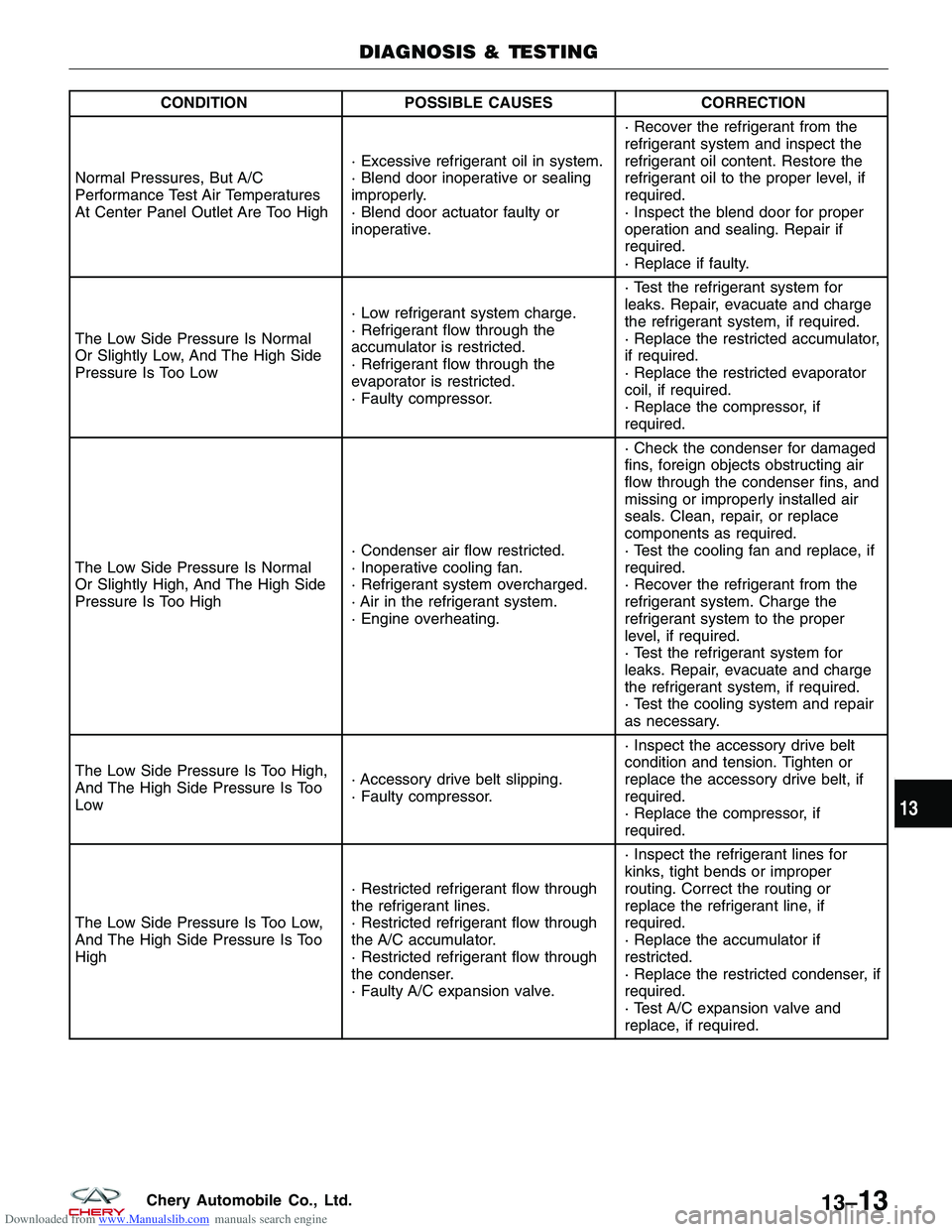
Normal Pressures, But A/C
Performance Test Air Temperatures
At Center Panel Outlet Are Too High · Excessive refrigerant oil in system.
· Blend door inoperative or sealing
improperly.
· Blend door actuator faulty or
inoperative.· Recover the refrigerant from the
refrigerant system and inspect the
refrigerant oil content. Restore the
refrigerant oil to the proper level, if
required.
· Inspect the blend door for proper
operation and sealing. Repair if
required.
· Replace if faulty.
The Low Side Pressure Is Normal
Or Slightly Low, And The High Side
Pressure Is Too Low · Low refrigerant system charge.
· Refrigerant flow through the
accumulator is restricted.
· Refrigerant flow through the
evaporator is restricted.
· Faulty compressor.· Test the refrigerant system for
leaks. Repair, evacuate and charge
the refrigerant system, if required.
· Replace the restricted accumulator,
if required.
· Replace the restricted evaporator
coil, if required.
· Replace the compressor, if
required.
The Low Side Pressure Is Normal
Or Slightly High, And The High Side
Pressure Is Too High · Condenser air flow restricted.
· Inoperative cooling fan.
· Refrigerant system overcharged.
· Air in the refrigerant system.
· Engine overheating.· Check the condenser for damaged
fins, foreign objects obstructing air
flow through the condenser fins, and
missing or improperly installed air
seals. Clean, repair, or replace
components as required.
· Test the cooling fan and replace, if
required.
· Recover the refrigerant from the
refrigerant system. Charge the
refrigerant system to the proper
level, if required.
· Test the refrigerant system for
leaks. Repair, evacuate and charge
the refrigerant system, if required.
· Test the cooling system and repair
as necessary.
The Low Side Pressure Is Too High,
And The High Side Pressure Is Too
Low · Accessory drive belt slipping.
· Faulty compressor.· Inspect the accessory drive belt
condition and tension. Tighten or
replace the accessory drive belt, if
required.
· Replace the compressor, if
required.
The Low Side Pressure Is Too Low,
And The High Side Pressure Is Too
High · Restricted refrigerant flow through
the refrigerant lines.
· Restricted refrigerant flow through
the A/C accumulator.
· Restricted refrigerant flow through
the condenser.
· Faulty A/C expansion valve.· Inspect the refrigerant lines for
kinks, tight bends or improper
routing. Correct the routing or
replace the refrigerant line, if
required.
· Replace the accumulator if
restricted.
· Replace the restricted condenser, if
required.
· Test A/C expansion valve and
replace, if required.
DIAGNOSIS & TESTING
13
13–13Chery Automobile Co., Ltd.
Page 1517 of 1903
Downloaded from www.Manualslib.com manuals search engine DIAGNOSIS & TESTING
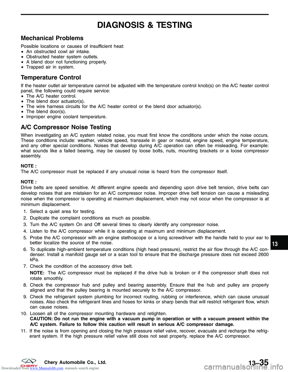
Mechanical Problems
Possible locations or causes of insufficient heat:
•An obstructed cowl air intake.
• Obstructed heater system outlets.
• A blend door not functioning properly.
• Trapped air in system.
Temperature Control
If the heater outlet air temperature cannot be adjusted with the temperature control knob(s) on the A/C heater control
panel, the following could require service:
•The A/C heater control.
• The blend door actuator(s).
• The wire harness circuits for the A/C heater control or the blend door actuator(s).
• The blend door(s).
• Improper engine coolant temperature.
A/C Compressor Noise Testing
When investigating an A/C system related noise, you must first know the conditions under which the noise occurs.
These conditions include: weather, vehicle speed, transaxle in gear or neutral, engine speed, engine temperature,
and any other special conditions. Noises that develop during A/C operation can often be misleading. For example:
what sounds like a failed bearing, may be caused by loose bolts, nuts, mounting brackets or a loose compressor
assembly.
NOTE :
The A/C compressor must be replaced if any unusual noise is heard from the compressor itself.
NOTE :
Drive belts are speed sensitive. At different engine speeds and depending upon drive belt tension, drive belts can
develop noises that are mistaken for an A/C compressor noise. Improper drive belt tension can cause a misleading
noise when the compressor is operating at maximum displacement, which may not occur when the compressor is at
minimum displacement.
1. Select a quiet area for testing.
2. Duplicate the complaint conditions as much as possible.
3. Turn the A/C system On and Off several times to clearly identify any compressor noise.
4. Listen to the A/C compressor while it is operating at maximum and minimum displacement.
5. Probe the A/C compressor with an engine stethoscope or a long screwdriver with the handle held to your ear to better localize the source of the noise.
6. To duplicate high-ambient temperature conditions (high head pressure), restrict the air flow through the A/C con- denser. Install a manifold gauge set or a scan tool to ensure that the discharge pressure does not exceed 2600
kPa.
7. Check the condition of the accessory drive belt. NOTE: The A/C compressor must be replaced if the drive hub is broken or if the compressor shaft does not
rotate smoothly.
8. Check the compressor hub and pulley and bearing assembly. Ensure that the hub and pulley are properly aligned and that the pulley bearing is mounted securely to the A/C compressor.
9. Check the refrigerant system plumbing for incorrect routing, rubbing or interference, which can cause unusual noises. Also check the refrigerant lines and hoses for kinks or sharp bends that will restrict refrigerant flow, which
can cause noises.
10. Loosen all of the compressor mounting hardware and retighten. CAUTION: Do not run the engine with a vacuum pump in operation or with a vacuum present within the
A/C system. Failure to follow this caution will result in serious A/C compressor damage.
11. If the noise is from opening and closing the high pressure relief valve, recover, evacuate and recharge the refrig- erant system. If the high pressure relief valve still does not seat properly, replace the A/C compressor.
13
13–35Chery Automobile Co., Ltd.
Page 1522 of 1903
Downloaded from www.Manualslib.com manuals search engine CAUTION:
The A/C accumulator and the A/C liquid line must be replaced if an internal failure of the A/C com-
pressor has occurred. Failure to replace the A/C accumulator and the A/C liquid line can cause
serious damage to the replacement A/C compressor.
NOTE :
When replacing multiple A/C system components, determine how much oil should be removed from the new A/C
compressor.
NOTE :
Replacement of the refrigerant line O-ring seals and gaskets is required anytime a refrigerant line is opened. Failure
to replace the rubber O-ring seals and metal gaskets could result in a refrigerant system leak.1. Evacuate the A/C system (See A/C System Evacuation and Recharge in Section 13 Heating & Air Conditioning).
2. Disconnect the A/C compressor electrical connector.
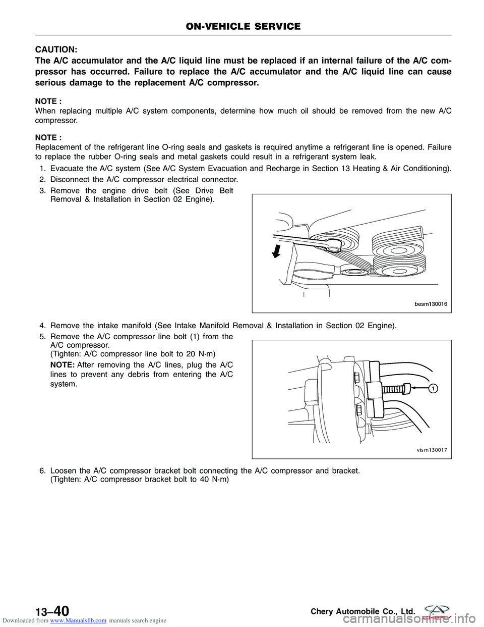
3. Remove the engine drive belt (See Drive Belt Removal & Installation in Section 02 Engine).
4. Remove the intake manifold (See Intake Manifold Removal & Installation in Section 02 Engine).
5. Remove the A/C compressor line bolt (1) from the A/C compressor.
(Tighten: A/C compressor line bolt to 20 N·m)
NOTE: After removing the A/C lines, plug the A/C
lines to prevent any debris from entering the A/C
system.
6. Loosen the A/C compressor bracket bolt connecting the A/C compressor and bracket. (Tighten: A/C compressor bracket bolt to 40 N·m)
ON-VEHICLE SERVICE
BESM130016
VISM130017
13–40Chery Automobile Co., Ltd.
Page 1523 of 1903
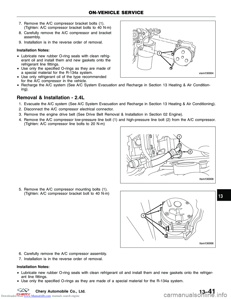
Downloaded from www.Manualslib.com manuals search engine 7. Remove the A/C compressor bracket bolts (1).(Tighten: A/C compressor bracket bolts to 40 N·m)
8. Carefully remove the A/C compressor and bracket assembly.
9. Installation is in the reverse order of removal.
Installation Notes:
• Lubricate new rubber O-ring seals with clean refrig-
erant oil and install them and new gaskets onto the
refrigerant line fittings.
• Use only the specified O-rings as they are made of
a special material for the R-134a system.
• Use only refrigerant oil of the type recommended
for the A/C compressor in the vehicle.
• Recharge the A/C system (See A/C System Evacuation and Recharge in Section 13 Heating & Air Condition-
ing).
Removal & Installation - 2.4L
1. Evacuate the A/C system (See A/C System Evacuation and Recharge in Section 13 Heating & Air Conditioning).
2. Disconnect the A/C compressor electrical connector.
3. Remove the engine drive belt (See Drive Belt Removal & Installation in Section 02 Engine).
4. Remove the A/C compressor low-pressure line bolt (1) and high-pressure line bolt (2) from the A/C compressor.
(Tighten: A/C compressor line bolts to 20 N·m)
5. Remove the A/C compressor mounting bolts (1). (Tighten: A/C compressor bracket bolt to 40 N·m)
6. Carefully remove the A/C compressor assembly.
7. Installation is in the reverse order of removal.
Installation Notes:
• Lubricate new rubber O-ring seals with clean refrigerant oil and install them and new gaskets onto the refriger-
ant line fittings.
• Use only the specified O-rings as they are made of a special material for the R-134a system.
ON-VEHICLE SERVICE
VISM130004
LTSM130008
LTSM130006
13
13–41Chery Automobile Co., Ltd.
Page 1530 of 1903
Downloaded from www.Manualslib.com manuals search engine RESTRAINTS
14
CONTENTSpage
Airbag System ....................................................................... 14-1
Seat Belt System .................................................................... 14-50
AIRBAG SYSTEM
GENERAL INFORMATION14-2
Description 14-2
Operation 14-2
Specifications 14-2
Special Tools 14-3
Electrical Schematics 14-4
Airbag Control Module Connector Pin-Out
Table 14-7
DIAGNOSIS & TESTING14-8
Diagnostic Help 14-8
Intermittent DTC Troubleshooting 14-8
Ground Inspection 14-8
Diagnostic Tools 14-8
Diagnostic Trouble Code (DTC) List 14-9
Restraints Control Module DTC List 14-9
Diagnostic Trouble Code (DTC) Tests 14-11
B1102 - Battery Voltage Low 14-11
B1346 - Driver Airbag Resistance Too
High Or Open (1st Stage) 14-16B1352 - Passenger Airbag Resistance
Too High Or Open (1st Stage)
14-23
B2501 - Warning Lamp Fault-Open 14-29
B2503 - Warning Lamp Fault-Short To
Ground 14-33
B2504 - Warning Lamp Fault-Short To
Battery 14-37
B1620 - Internal Fault - Replace ECU 14-41ON-VEHICLE SERVICE14-46
Airbag System Disarming Procedure 14-46
Description 14-46
Driver Side Airbag 14-46
Removal & Installation 14-46
Front Passenger Side Airbag 14-47
Removal & Installation 14-47
Restraints Control Module (RCM) 14-49
Removal & Installation 14-49
14
14–1Chery Automobile Co., Ltd.
Page 1531 of 1903

Downloaded from www.Manualslib.com manuals search engine GENERAL INFORMATION
Description
Available occupant restraints for this vehicle include both active and passive types. Active restraints are those which
require the vehicle occupants to take some action to employ, such as fastening a seat belt; while passive restraints
require no action by the vehicle occupants to be employed.
Active Restraints
•Front Seat Belts
• Rear Seat Belts
Passive Restraints
• Driver Airbag
• Passenger Airbag
• Seat Belt Tensioners
Operation
Active Restraints
The primary passenger restraints are the seat belts. Seat belts are referred to as an active restraint because the
vehicle occupants are required to physically fasten and properly adjust these restraints in order to benefit from them.
Passive Restraints
The passive restraints are referred to as a supplemental restraint system because they were designed and are
intended to enhance the protection for the occupants of the vehicle only when used in conjunction with the seat belts.
They are referred to as passive restraints because the vehicle occupants are not required to do anything to make
them operate; however, the vehicle occupants must be wearing their seat belts in order to obtain the maximum safety
benefit from the supplemental restraint system.
The supplemental restraint system electrical circuits are continuously monitored and controlled by a microprocessor
and software contained within the Restraints Control Module (RCM). An airbag indicator in the instrument cluster
illuminates for about seven seconds as a bulb test each time the ignition switch is turned to the ON or START posi-
tions. Following the bulb test, the airbag indicator is turned ON or OFF by the RCM to indicate the status of the
supplemental restraint system. If the airbag indicator comes ON at any time other than during the bulb test, it indi-
cates that there is a problem in the supplemental restraint system electrical circuits. Such a problem may cause
airbags not to deploy when required, or to deploy when not required.
Deployment of the supplemental restraints depends upon the angle and severity of an impact. When an impact is
severe enough, the microprocessor in the RCM signals the inflator of the appropriate airbag units to deploy their
airbag cushions. The front seat belt tensioners are provided with a deployment signal by the RCM in conjunction with
the front airbags.
Specifications
Torque Specifications
DESCRIPTION TORQUE (N·m)
Driver Side Airbag Retaining Bolts 10
Restraints Control Module Retaining Bolts 7-9
Front Passenger Side Airbag Retaining Bolts 10
14–2Chery Automobile Co., Ltd.
Page 1536 of 1903

Downloaded from www.Manualslib.com manuals search engine Airbag Control Module Connector Pin-Out Table
PINCIRCUIT IDENTIFICATION PINCIRCUIT IDENTIFICATION
1 Driver Seatbelt Pre-tensioner Lo 14Front Passenger Airbag Lo
2 Driver Seatbelt Pre-tensioner Hi 15-
3 Front Passenger Seatbelt Pre-tensioner Hi 16 -
4 Front Passenger Seatbelt Pre-tensioner Lo 17 -
5 Ignition Switch 18-
6 GND 19-
7 Airbag Lamp 20-
8 -21 -
9 Diagnostic Link K 22-
10 Driver Airbag Lo 23-
11 Driver Airbag Hi 24-
12 -25 -
13 Front Passenger Airbag Hi
GENERAL INFORMATION
14
14–7Chery Automobile Co., Ltd.
Page 1539 of 1903

Downloaded from www.Manualslib.com manuals search engine DTCDTC DEFINITION
B1515 Buckle Switch Driver Defect
B1516 Buckle Switch Passenger Defect
B1527 Passenger Airbag Deactivation Switch Open Or Short To Battery
B1528 Passenger Airbag Deactivation Switch Short Or Short To Ground
B1529 Passenger Airbag Deactivation Switch Defect
B1650 Crash Record In 1st Stage Only (Frontal - Replace ECU)
B1657 Crash Record In Belt Pretensioner Only
B1658 Belt Pretensioner 6 Times Deployment
B1620 Internal Fault - Replace ECU
B2501 Warning Lamp Fault - Open
B2503 Warning Lamp Fault - Short To Ground
B2504 Warning Lamp Fault - Short To Battery
B2505 Passenger Airbag Off Warning Lamp Failure
DIAGNOSIS & TESTING
14–10Chery Automobile Co., Ltd.