Page 393 of 426

________________________________________________ E_ m ___ e_r .::g :...e_ n _ c_,!y:._ s_ i_t _u _a_ t_ i_o _n_ s _--J_
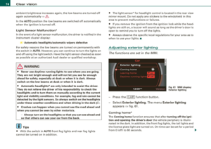
- Screw the towing loop t ightly into the threaded hole as
far as it will go::::>
page 390, fig. 315.
When it is no longer needed, unscrew the towing loop and put it
back into the vehicle toolkit. Be sure to have the towing loop stored
in the vehicle at all times.
When installing the grill for the air duct, be sure that the tabs on the
gril l are first inserted into their guides on the vehicle above the
fog lamp. Then position the opposite side of the grill
=> page 390,
fig. 314 ® and push it firmly into its guide.
& WARNING
If the towing loop is not screwed in as far as it will go, the thread
can pull out when the vehicle is towed -potential risk of an
accident. •
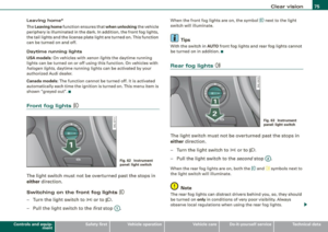
Rear towing loop
Do not install the rear towing loop until it is needed.
Fig. 316 Rear bumper:
Cover Fig
. 317 Rear bumper:
Screwing in towing
loop
At the right rear behind a cover in the bumper, there is a
threaded opening with
a left-hand thread into which the
towing loop is screwed.
- To release the cover from the bumper, press it in by
applying short, sharp pressure to the outer part
==> fig. 316.
- Remove the towing loop from th e vehicle tool kit.
- Screw the towing loop tightly into the threaded hole as
far as it will go ::::> fig. 317.
Unscrew the towing loop again after use and instal l the cover in the
bumper. Return the towing loop to the toolkit. Be sure to have the
towing loop stored in the vehicle at all times .
& WARNING
If the towing loop is not screwed in as far as it will go, the thread
can pull out when the vehicle is towed -potential risk of an
accident. •
Vehicle care Do-it-yourself service irechnical data
Page 394 of 426
lll9.,___E_ m_ e_ r -'g==-- e_n _ c_ y=--- s_ i_ t _u _a _ t_ i_o _n _ s _____________________________________________ _
Loading the vehicle onto a flat bed truck
Front hook up
Fig. 318 Vehicle on flat
bed truck
- Align the vehicle w ith the centerline of the car carrier
ramp.
- Attach the winch hook to the front towline eye p reviously
installed.
Rear hook up
- Align the vehicle with the centerline of the car carrier
ramp.
- Attach the winch hook to the rear towline eye prev iously
i nstalled.
[ i ) Tips
Check carefully to make sure the hook -up is secure before moving
the car up the fla tbed truck ramp. •
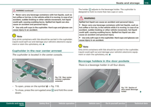
Lifting vehicle
Lifting with workshop hoist and with floor
jack
The vehicle may only be lifted at the lifting points illus
trated.
- Read and heed WARNING=>& .
Fig. 319 Front lifting
point
Fig. 320 Rear lifting
point
- Locate lifting points=> fig. 319 => fig. 320.
- Adjust lifting arms of workshop hoist or floor jack to
match vehicle lifting points.
Page 395 of 426

________________________________________________ E _m_ e_r.:g :;,. e_ n_c ...: y:.- s_ i_ t _u _a_ t_ i_ o _ n_ s __ lllll
•
- Inse rt a rubbe r pad betwee n th e floo r ja ck/work shop
h oi st an d the lift ing p oin ts.
If you must lift your vehicle with a floor jack to wo rk underneath , be
sure the veh icle is safely supported on stands intended for this
purpose .
Front lifting point
T he lift ing p oint i s located o n th e flo or pan rei nforce men t about at
the same l eve l as th e jac k m ounting point=> page
392 , fig. 3 19 . Do
not lift the vehicle at the vertical sill reinforcement.
Rear lifting point
The li fti ng poi nt is located on the ve rt ical re in forceme nt of t he low er
sill for the on board jack=> page
392 , fig. 320.
Lifting with vehi cle ja ck
R efer to => page
376 .
& WARNING
• To reduce the risk of serious injury and vehicle damage.
-Always l ift the vehicle only at the special workshop hoist and
floor jack lift points illustrated => page
392 , fig. 319 and
=> page
392 , fig. 320.
- Failure to lift the vehicle at these points could cause the
vehicle to tilt or fall from a lift if there is a change in vehicle
weight distribution and balance . This might happen , for
e x ample , when heavy components such as the engine block or
transmission are removed .
• When remo ving heavy components like these, anchor vehicle
to hoist or add correspond ing we ights to maintain the center of
gravity. Otherwise , the vehicle might tilt or slip off the hoi st,
c ausing serious personal injury .
0 Note
• Be awar e of the fo llow ing po ints before l ifting t he ve hicle:
- The vehicle should never be lifted or jacked up from unde r
neath the engine oil pan , the transmission housing , the front or
rear a xle or the body side members. This could lead to serious
damage.
- To avoid damage to the underbody or chassis frame, a rubber
pad must be in serted between the floor jack and the lift po ints .
- Before driving over a workshop ho ist, check that the vehicle
weight does not exceed the permissible lifting capacity of the hoist.
- Before driving over a workshop hoist , ensure that there is
sufficient clearance between the hoist and low parts of the
vehicle. •
Do-it-yourself service
Page 396 of 426
Page 397 of 426
~
.> -
\\
o:i,
o.0. \'?> ...........
... ~ 'A
Page 398 of 426

1111....__G_ e_ n_ e_r_a _ l_ i _n_ f_ o_ rm_ a _t_io _ n _______________________________________________ _
General information
Explanation of technical data
Some of the technical data listed in this manual requires
further explanation.
The technical data for your vehicle is listed in the charts starting on
~ page 399 . This section provides general information, notes and
restrictions which app ly to this data. •
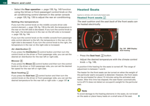
Vehicle identification
The key data is given on the vehicle identification number
(VIN) pla te and the vehicle data st icker.
F ig. 3 21 Vehicl e Id enti
fi ca tion N umber (V IN)
pl ate : lo cation on
d riv er 's s id e das h
pan el F
ig . 3 22 Th e vehi cle
i d e ntifi cat ion la be l -
i nside the luggag e
com partm ent
The Vehicle Id enti fication Numb er (V IN)
is located on the driver's side so that it is visible from the outside
through the windshield ~ fig . 32 1.
Th e veh icle i de ntifi cat ion lab el
is located in the luggage compar tment near the battery.
The label~ fig. 322 shows the following vehic le data :
0 Production control No.
0 Vehicle identification No.
G) Type code number
© Type designation/engine output in Ki lowatts
@ Engine and transmission code letter
© Paint No./lnterior
0 Optiona l equipment No.'s
Vehicle data 2 to 7 are also found in your Warranty
& Maintenance
booklet.
Th e s afety c ompliance sticker
is your assurance that your new vehicle complies with a ll app licable
Federa l Motor Vehicle Safety Standards which were in effect at the
time the vehicle was manu factured. You can find this sticker on the
left door jamb . It shows the month and year of production and the .._
Page 399 of 426

_________________________________________________ G_ e_ n_ e_r _a _l_ i_n _f_o _ r_ m_ a_ t _i _o _ n __ ll'II
v e hic le identificatio n number of your vehic le (p erforation) as well as
th e G ro ss V ehic le We ight Rat ing (GVWR) an d the Gro ss A xle We ig ht
R ating (GAWRl .
The high voltage warning label is located on the lock carrier.
The spark ignition system complies with the Canadian standard ICES-002 . •
Displaying Vehicle Identification
Number in the MMI
Fig . 323 MMI di splay :
Vehicle ID number
(VIN)
Y ou can also display t he Vehi cle Id ent ifi catio n Num ber of
y o ur vehi cle in the MM I.
- Pre ss th e
(CA RI fun ctio n bu tton.
- Selec t
Vehicle ID number (VIN) . The Vehicle ID number
(VIN)
m enu appea rs=> fig. 3 23 . •
Controls and equip
ment Safety first Vehicle operation
Weights
Gross Vehicle Weight Rating
The G ross Ve hicle We ight Rating (GVWR), a nd the Gross A xle Weight
R ating (GAW R) for front and rear are l isted on a stic ker on the left
doo r jamb .
T he G ross Ve hicle We igh t R ating includes t he weight o f the bas ic
vehic le plus full fue l tank , oil and coo lant, p lus maximum load,
w hi ch includes passe nger we ight (1 50 lbs/68 kg per des ignat ed
seat ing position) and luggage weight:::::,&.
Gross Axle Weight Rating
The Gross Axle Weight Rating is the maximum load that can be
ap plied at each axl e of the vehicle:::::, .&,.
Vehicle capacity weight
The vehic le capacity weig ht (max. load) is list ed e ither on the
driver's side B -pillar or ins ide the fuel fi ller flap.
Roof weight
The maxi mum pe rm is s ible roof we ig ht i s 220 lb (100 kg ). The ro of
we ight is made up of th e wei ght of t he roof rack system an d the
we igh t of t he o bjec t being tra nspo rted :::::, page 1 13, "Lo adi ng the
roo f rack".
& WARNING
• The Gross Vehi cle Weight Rating for your Audi 07 vehi cle ,
found on the safety compliance label on the driver's side B -pillar ,
must never be exceeded under any circumstances . Exceeding the
Gross Vehicle Weight Rating of your vehicle is likely to damage
your vehicle , and such damage will not be covered by your Limited
New Vehicle Warranty . Exceeding the Gross Vehicle Weight Rating
will also change the performance and handling characteristics of
your veh icle , which could cause a crash resulting in serious injury
or death. .,_
Vehicle care Do-it-yourself service Tec hn ica l da ta
Page 400 of 426

___ G_ e_n_ e _ r_a _l _ i_n _f_o _ r_ m_ a_ t_ i_ o _ n ________________________________________________ _
& WARN ING (continued )
• The Gro ss Veh icle Weight R ating for y our Audi 07 would be
e xc eeded if your vehicle is simult aneously equipped with
P a nor amic slid ing sunroof ; thi rd-ro w seating ; trailer tow ing equ ip
ment (factory or deale r-inst alled ), and running bo ards (de aler
in stalled) . UNDER NO CIRCUMSTANCES MAY ALL SUCH ITEM S BE
IN STALLED ON THE SAME VEHICLE.
• The a ctual Gros s Axle We ight R ating at the front and rear axles
s hould not e xceed the p ermi ssible weight s, and their comb ination
mu st not e xceed the Gross Vehi cle Weight Rati ng .
• Exc eeding perm issible weight rating s can result in vehi cle
d amage , a cc ident s and per son al inj ury.
0 Note
• The vehicle capacity weight figures apply when the load is
distr ibuted evenly in the vehic le (passengers a nd luggage) . When
transporting a heavy load in the luggage compartment, carry the load as near to the rear ax le as possible so that the vehic le's
handling is not impaired.
• Do not exceed the maximum perm issible axle loads or the
maximum gross vehic le weight. Always remember that the vehicle's
handling will be af fected by the extra load. Therefore, adjust your
speed according ly .
• Always observe local regulations .•
Dimensions
The specifications refer to the basic mode l. Differences may occur
depending on the mode l type and options ordered, for example, tire
s izes .
0 Note
When driving up steep ramps, on rough roads, over curbs, etc. it is
important to remember that some parts of your vehic le, such as
spo ilers or exhaust system components, may be c lose to the
ground. Be carefu l not to damage them. •