Page 81 of 115
 so that the puncture is at the bottom.
4. Remove")
Tire repair
10-5
Roadside emergencies
Note: In cold conditions, use the vehicle’s
heater to warm the aerosol.
3. Position the wheel (if possible) so that the puncture is at the bottom.
4. Remove the valve cap and clean the valve thread.
5. Vigorously shake the tire sealant for approximately 30 seconds.
6. Screw the filler tube onto the tire valve and break the safety seal.
7. Hold the tire sealant upright and turn the knob one-quarter turn clockwise. If you
need to stop the process, simply turn the
knob back to the ‘OFF’ position.
8. Empty the entire contents of the tire sealant into the tire. When the sealant
stops flowing through the filler tube, turn
the knob to the ‘OFF’ position and
unscrew the filler tube from the tire valve.
Note: If tire sealant comes into contact
with the vehicle’s paint, immediately
wash the area with water to avoid
permanent damage.
9. If the wheel rim has lifted from the ground, drive immediately for 6 to 12
miles (10 to 20 km) to distribute the
sealant evenly inside the tire. Then drive
gently and do not exceed 30 mph
(45 km/h).
WARNING: If the wheel rim has not
lifted from the ground, call
Roadside Assistance to have the vehicle
transported to a repair facility.
�S
10. Drive to the nearest service station and inflate the tire to the correct pressure (see
Specifications and tire pressures,
page 11-4 .) If the required pressure
cannot be reached, then the tire is too
severely damaged and you should have
the vehicle transported to a tire repair
facility. Do not drive!
Note: When adjusting tire pressures, you
can display tire pressure values on the
Touch Screen’s tire pressure screen.
However, the values displayed by the
Touch Screen will not be updated until
you place the car in drive long enough for
the tire pressure monitoring sensors to
take new readings. For details, refer to the
Touch Screen Users Manual provided in
your owners package.
11. If the correct tire pressure was achieved, continue driving. Drive carefully and do
not exceed 30 mph (45 km/h). At the
earliest opportunity, have the tire
repaired or replaced and replace the used
tire sealant.
WARNING: Always inform the tire
repairer that tire sealant has been
used. If the tire is to be subsequently
deflated, only do so in a well ventilated
area. The aerosol sealant can damage the
wheel sensor that measures tire pressure.
Therefore, the wheel sensor must be
replaced.
�S
Replacing the tire sealantAlways replace the used tire sealant with one
of the same type and capacity (400 ml). Tire
sealants are available through most reputable
automotive retailers.
Roadster OHB.book Page 5 Th ursday, October 2, 2008 8:59 AM
Page 82 of 115

Wheels10-6
Roadside emergencies
WheelsRemoving the wheel
WARNING: Never work under the
vehicle with a jack as the only means of
support. If the vehicle slips off the jack, you or
someone else could be seriously injured.
�S
1. Apply the hand brake and remove the key from the starter switch.
2. Loosen each lug bolt one turn using the wheel bolt extension tool, the locking
wheel bolt adapter (located in the tool
kit), and a 17 mm socket and/or a wheel
wrench.
3. Position a jack at the jacking points identified on the vehicle (see Ve h i c l e
jacking points, page 10-11 ), and raise the
vehicle.
Caution: Jacking the vehicle from
any point other than those
specified can damage the vehicle.
4. Remove the lug bolts and store in a safe place. 5. Remove the wheel.
Caution: Place the wheel face up to
avoid scratching the surface.
Replacing the wheel
WARNING: Before replacing the wheel,
inspect the mating faces of the wheel
and hub. Remove any corrosion, dirt or
foreign material. Fitting the wheels without
correct surface-to-surface contact can cause
the wheel bolts to loosen, resulting in a loss of
vehicle control.
�S
1. Position the wheel on the hub.
2. Fit the wheel bolts and tighten until the wheel is firmly seated against the hub.
3. Lower the vehicle and remove the jack.
4. Using a torque wrench, fully tighten the bolts in the sequence shown to 77 lbft
(105 Nm). 5. Return the wheel bolt extension tool and
the locking wheel bolt adapter to the tool
kit.
6. Check and tighten the wheel bolts every 1000 miles (1600 km).
TR0055
1
4
3
5
2
1
4
3
5
2
TR0151
Roadster OHB.book Page 6 Th ursday, October 2, 2008 8:59 AM
Page 83 of 115

Fuse replacement
10-7
Roadside emergencies
Fuse replacementReplacing a fuse
WARNING: Use replacement fuses of
the same rating and type or fuses of
matching specification. Incorrect fuse ratings
can overload a system and cause a fire or
malfunction. Blown fuses should be replaced
and no attempt should be made to repair a
blown fuse.
�S
Fuses protect the vehicle’s electrical systems
from damage. The failure of any fuse will
render the equipment it protects inoperative.
1. Before removing a fuse, turn off all electrical equipment and remove the key
from the starter switch.
2. Locate the fuse box. The fuse box is located behind the access panel on the
passenger side of the dashboard.
3. Open the panel to access the fuses. Remove the panel by using the
screwdriver supplied in the toolkit to rotate the fastener 90° counterclockwise,
then release the panel from the
dashboard.
4. Consult the fuse specification chart to determine which fuse is protecting the
non-functioning electrical system.
Note: A label is also affixed to the inside
of the panel.
5. Remove the appropriate fuse and replace with a fuse of the same amperage as the
original. If in doubt, check the fuse
specification chart on the following
pages.
6. Re-install the fuse panel by aligning the hinges at the bottom of the panel with
the slots on the surrounding dashboard
area. Secure the panel by rotating the
fastener 90° clockwise.
If a replacement fuse fails to solve an
electrical failure, or the replacement fuse fails
prematurely, contact Tesla Motors.TR0048
13579 2468
11 13 15 17
20 22 24 26
10 12 14 16 18 19 21 23 25 27
Fuse colors
Fuse color
Rating (amps)
Orange 5
Brown 7.5
Red 10
Blue 15
Yellow 20
Clear 25
Green 30
Roadster OHB.book Page 7 Th ursday, October 2, 2008 8:59 AM
Page 84 of 115

Circuit protected
1 10Anti-lock Braking System (ABS)
2 15Auxiliary power socket
3 20Heating and ventilation")
Fuse replacement10-8
Roadside emergencies
Fuse specification chartFuse number
Rating (amps)
Circuit protected
1 10Anti-lock Braking System (ABS)
2 15Auxiliary power socket
3 20Heating and ventilation fan
4 15Windshield wiper motor and washer
5 7.5Electrical accessories, audio and navigation systems
6 10Turn signals and side lights
7 10Starter key in ‘ON’ position
85 In stru m en ts
91 0Horn
10 7.5Interior and trunk lights
11 20Interior lighting and seat heaters
12 20Radiator cooling fan 1
13 20Radiator cooling fan 2
14 7.5Starter key in ‘ACC’ position
15 15Driver side headlight - low beam
16 15Passenger side headlight - low beam
17 15Driver side headlight - high beam
18 15Passenger side headlight - high beam
19 20Passenger window
20 20Driver window
21 10Central door locking
22 7.5Brake pump
23 15Heating, ventilation, and accessory power socket
24 15Audio system amplifier
25 30Starter key in ‘ON’ position
26 5Brake lights
27 7.5Driver controls - heating and ventilation
Roadster OHB.book Page 8 Th ursday, October 2, 2008 8:59 AM
Page 85 of 115

Bulb replacement
10-9
Roadside emergencies
Bulb replacementReplacing a bulbAlways check the operation of all exterior
lights before driving the vehicle. Replace a
bulb only with one of the same type and
specification.Light Emitting Diode (LED) lightsThe following lights on your vehicle use the
latest LED technology and if any of these
lights stop working, it must be replaced by
Te s l a M o t o r s :
• Front side marker light
• Rear side marker light
• Reverse lights
• Tail/brake lights
• Rear turn signals
Unlike traditional filament bulbs, these lights
have a long life and low power consumption
while providing the same amount of
illumination.Filament bulbsThe lights shown in the illustration and listed
below have replaceable filaments that should
be replaced by Tesla Motors:
• Front turn signal ( 1)
• Front side (2 )
• Headlight high beam ( 3)
• Headlight low beam (4 )
Owner replaceable bulbsThe interior light, trunk light, and license plate
lights are easy to replace. To replace these
lights, refer to the following table and
instructions.
Interior lightTo r e m o v e t h e b u l b :
1. Using the screwdriver supplied in the toolkit, depress the retaining clips and
carefully pry the light unit from the rear
header rail.
2. Rotate the bulb holder 90° counterclockwise and remove.
3. Pull the bulb from the holder.
To install the new bulb, reverse the above
steps.
Location
Watts
Ty p e
Front turn signal (1) 21 PY21W
Front side (2) 5 W5W
Headlight high beam (3) 65 H9B
Headlight low beam (4) 60 HB3A
Location
Watts
Ty p e
Interior 5 W5W
Tr u n k 5 C 5 W
License plate 5 C5W
1
2
3
4
1
2
3
4
TR0163
TR0170
Roadster OHB.book Page 9 Th ursday, October 2, 2008 8:59 AM
Page 86 of 115
Bulb replacement10-10
Roadside emergencies
Tr u n k l i g h tTo r e m o v e t h e b u l b :1. Using the screwdriver supplied in the toolkit, remove the two screws securing
the light unit to the inside of the trunk.
2. Withdraw the light unit from the trunk and disconnect the two connectors.
3. Remove the lens from the light.
4. Spring the bulb holder clips apart to release the bulb.
To install the new bulb, reverse the above
steps.
License plate lightTo r e m o v e t h e b u l b : 1. Using the screwdriver supplied in the toolkit, remove the two screws securing
the light unit to the rear bumper.
2. Withdraw the light unit from the bumper and disconnect the two connectors.
3. Remove the lens from the light.
4. Spring the bulb holder clips apart to release the bulb.
To install the new bulb, reverse the above
steps.
TR0171
TR0172
Roadster OHB.book Page 10 Thursday, October 2, 2008 8:59 AM
Page 87 of 115
Raising the vehicle
10-11
Roadside emergencies
Raising the vehicleVehicle jacking pointsRefer to the illustration, and the labels on the
vehicle, for correct jacking locations. If lifting
the vehicle on a two-post lift, refer to the next
page.
1. Side jacking point
This point will raise both the front and
rear wheels.
2. Front jacking point Caution: Jacking the vehicle at any
other point will damage the underside
of the vehicle.
Caution: Use a suitable rubber or wood
pad to protect the chassis from surface
damage. Do not lift from a body panel. WARNING: Never raise a vehicle when
the charge cable is connected, even if
charging is not in progress. Always
disconnect the charge cable before raising
the vehicle.
�S
TR0137
11
22
Roadster OHB.book Page 11 Thursday, October 2, 2008 8:59 AM
Page 88 of 115
Raising the vehicle10-12
Roadside emergencies
Vehicle lifting points Refer to the illustration, and the labels on the
vehicle, for correct locations when lifting the
vehicle on a two-post lift. If jacking the
vehicle, refer to the previous page.
Before lifting on a two-post lift, you must
remove the rear undershield and fit rear lift
point adaptors 1 to the chassis. Rear lift point
adapters can be purchased from Tesla Motors. Position the arms of the two-post lift
under the rear lift point adapters and the
front jacking points 2.
WA R N I N G : D e a t h , s e r i o u s i n j u r y o r
vehicle damage can occur if the vehicle
is lifted on a two-post lift with the rear
undershield still in place.
�S
WARNING: Never raise a vehicle that is
plugged in. Always unplug the vehicle
before raising it.
�S
Caution: Rear lift point adaptors must
be used when lifting the vehicle on a
two-post lift.
TR0152
11
22
1
Roadster OHB.book Page 12 Thursday, October 2, 2008 8:59 AM
 1
1 2
2 3
3 4
4 5
5 6
6 7
7 8
8 9
9 10
10 11
11 12
12 13
13 14
14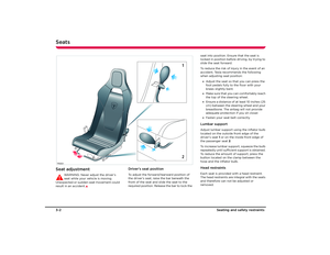 15
15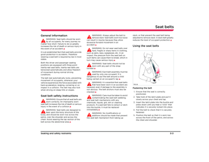 16
16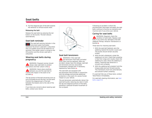 17
17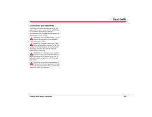 18
18 19
19 20
20 21
21 22
22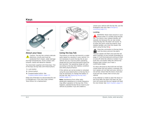 23
23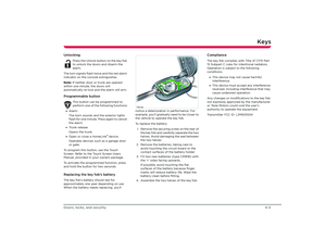 24
24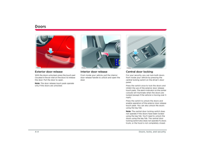 25
25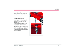 26
26 27
27 28
28 29
29 30
30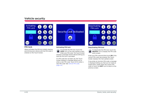 31
31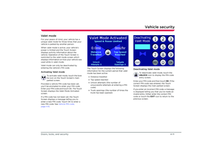 32
32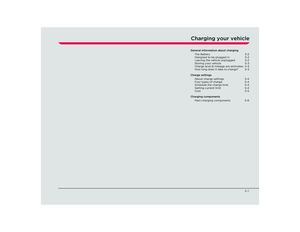 33
33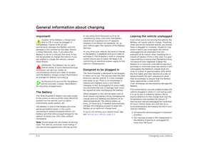 34
34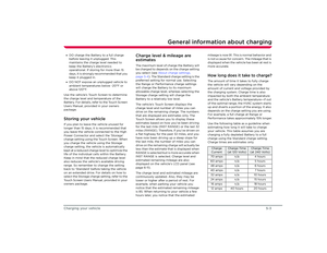 35
35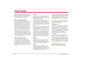 36
36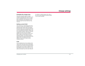 37
37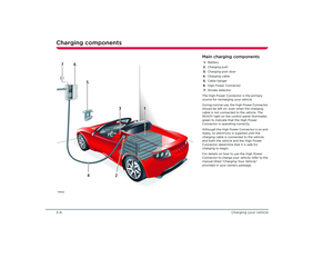 38
38 39
39 40
40 41
41 42
42 43
43 44
44 45
45 46
46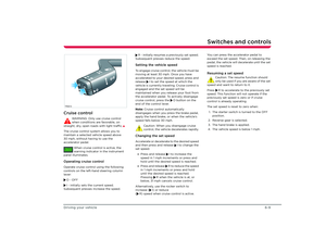 47
47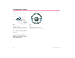 48
48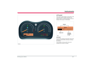 49
49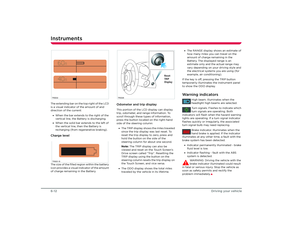 50
50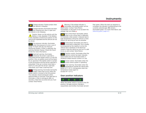 51
51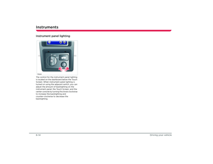 52
52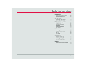 53
53 54
54 55
55 56
56 57
57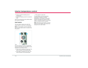 58
58 59
59 60
60 61
61 62
62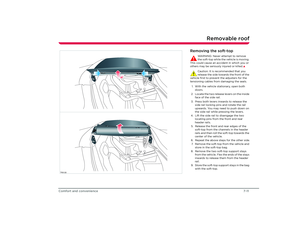 63
63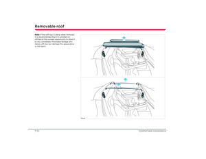 64
64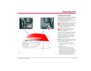 65
65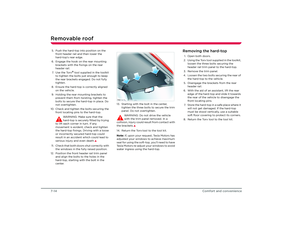 66
66 67
67 68
68 69
69 70
70 71
71 72
72 73
73 74
74 75
75 76
76 77
77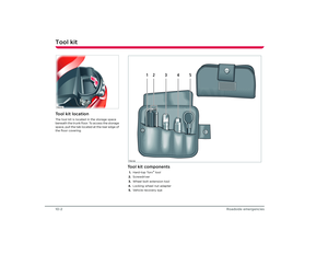 78
78 79
79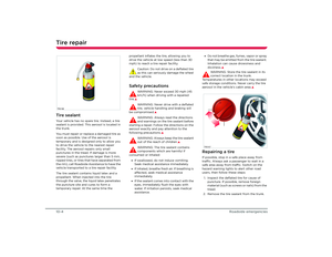 80
80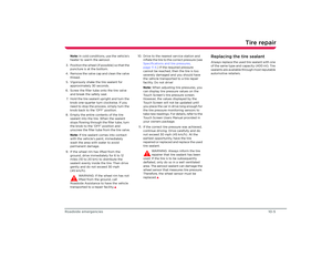 81
81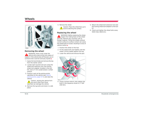 82
82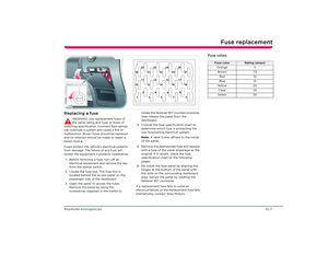 83
83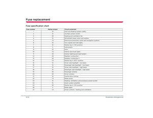 84
84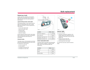 85
85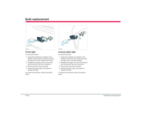 86
86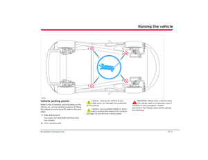 87
87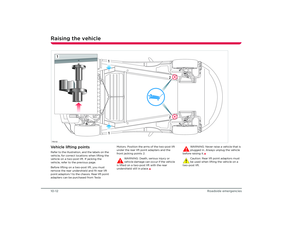 88
88 89
89 90
90 91
91 92
92 93
93 94
94 95
95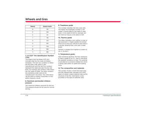 96
96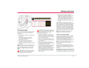 97
97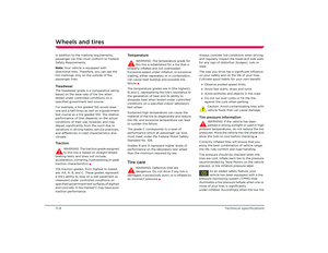 98
98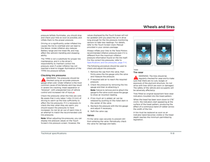 99
99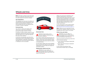 100
100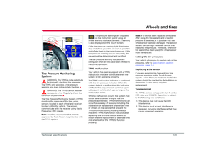 101
101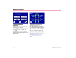 102
102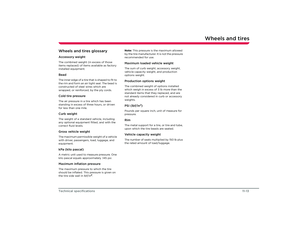 103
103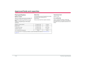 104
104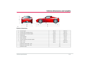 105
105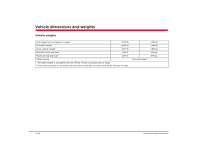 106
106 107
107 108
108 109
109 110
110 111
111 112
112 113
113 114
114

