Page 49 of 71

MULTIMEDIA
Fault finding - Fault finding charts
86C
86C-49V5 MR-372-J84-86C050$936.mif
ITS
Program No.: 0020
Vdiag No.: 04
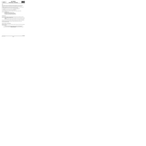
ALP 4 No traffic information messages appear on the screen
NOTESOnly check the customer complaint after performing a full check with the diagnostic
tool.
Check that the customer is using the navigation system correctly.
TMC road information is disseminated via the FM
band on the radio. The TMC pictogram should be
green in order for the traffic information to be
received.
What colour is the TMC pictogram?
Green
The system is operating correctly, but there is no
traffic information to be transmitted.
Check that the traffic information display has been
activated.
Press the INFO button and select the TMC traffic
information; Traffic information adjustment;
Card display menus.
Has the display been activated?
YES
Check that the traffic information settings are
correct.
Press the INFO button and select the TMC traffic
information; Traffic information adjustment;
Type of information to be displayed; Traffic
information service menus.
Make any necessary adjustments.
GreyNo traffic information is being received.
NOActivate the traffic information display.
AFTER REPAIRCarry out a complete check with the diagnostic tool.
ITS_V04_ALP4ITSJ84ph2V1.0
Page 50 of 71

MULTIMEDIA
Fault finding - Fault finding charts
86C
86C-50V5 MR-372-J84-86C050$936.mif
If any connection is faulty and if there is a repair
method (see Technical Note 6015A, Repairing
electrical wiring, Wiring: Precautions for repair),
repair the wiring; otherwise, replace the wiring.
ITS
Program No.: 0020
Vdiag No.: 04
ALP 5 Poor satellite reception
NOTESOnly check the customer complaint after performing a full check with the diagnostic
tool.
Check that the customer is using the navigation system correctly.
Ensure there are no present or stored faults.
Use the Wiring Diagrams Technical Note, Scenic II.
What colour is the GPS pictogram?
Green
The system operates normally.
Yellow
or
GreyPositioning is imprecise (yellow) or
impossible (grey) in the following areas:
forests, tunnels, valleys, under bridges
and in stormy weather.
Carry out a system test in an open area.
Check the condition and cleanliness of the
GPS aerial.
Check the insulation, continuity and
the absence of interference resistance
of connections 46CB and TB15 between
components 662 and 886.
NO Did it pass the tests?
YES
If the fault is still present, replace the GPS
aerial.
If the satellite reception is poor, contact
the Techline.
AFTER REPAIRCarry out a complete check with the diagnostic tool.
ITS_V04_ALP5ITSJ84ph2V1.0
Page 51 of 71

MULTIMEDIA
Fault finding - Fault finding charts
86C
86C-51V5 MR-372-J84-86C050$936.mif
ITS
Program No.: 0020
Vdiag No.: 04
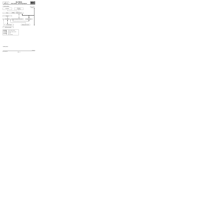
ALP 6The radio does not switch on automatically or switches off after
20 minutes
NOTESOnly check the customer complaint after performing a full check with the diagnostic
tool.
Check that the customer is using the navigation system correctly.
Use the Wiring Diagrams Technical Note, Scenic II.
The navigation system does not receive the multimedia wake-up signal when the + after ignition feed is
switched on.
Check the condition of the CD changer fuses (component code 1272).
Has the fault disappeared?
NO YES
On pressing the CD changer on/off button, check for
the multimedia wake-up signal on connection 34HU
on the radio's blue connector (component
code 261).
Is the check result correct?
NO
Check the insulation, continuity and the absence
of interference resistance of connection 34HU
between components 1272, 261, 1657, 1127
and 662.
If any connection is faulty and if there is a repair
method (see Technical Note 6015A, Repairing
electrical wiring, Wiring: Precautions for repair),
repair the wiring; otherwise, replace the wiring.
Has the fault disappeared?
NO YES
End of fault finding.
End of fault finding.
YESCheck for + 12 V (+ battery feed) on
connection BCP3 of the component 261
black connector.
Is the check result correct?
NO YES
Check the insulation, continuity and the
absence of interference resistance of
connection BCP3 between components 261
and 260.
If any connection is faulty and if there is a repair
method (see Technical Note 6015A,
Repairing electrical wiring, Wiring:
Precautions for repair), repair the wiring;
otherwise, replace the wiring.
Has the fault disappeared?
YES NO
AFTER REPAIRCarry out a complete check with the diagnostic tool.
ITS_V04_ALP6ITSJ84ph2V1.0
Page 52 of 71

MULTIMEDIA
Fault finding - Fault finding charts
86C
86C-52V5 MR-372-J84-86C050$936.mif
ITS
Program No.: 0020
Vdiag No.: 04
ALP 6
CONTINUED
Disconnect the connector of component 1272, check for + battery feed on connection BCP3, check for
+ accessories feed on connection SP2 and check for + after ignition feed on connection AP43 of the connector
of component 1272.
Also check that the earth on connection MAN is perfect.
Did it pass the tests?
No Yes
Check the continuity, insulation and absence of interference
resistance on the following connections:
●connection code SP2,
●connection code BCP3,
between components 1272 and 260;
●connection code AP43,
between components 1272 and 1337;
●connection code MAN,
between component 1272 and the earth MAN.
If any connection is faulty and if there is a repair method (see Technical
Note 6015A, Repairing electrical wiring, Wiring: Precautions for
repair), repair the wiring, otherwise, replace the wiring.
If the fault is still present, contact the Techline.
AFTER REPAIRCarry out a complete check with the diagnostic tool.
ITSJ84ph2V1.0
Page 53 of 71

MULTIMEDIA
Fault finding - Fault finding charts
86C
86C-53V5 MR-372-J84-86C050$936.mif
ITS
Program No.: 0020
Vdiag No.: 04
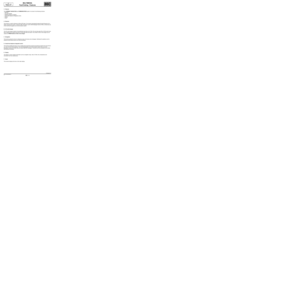
ALP 7 Clock not displayed or incorrect
NOTESOnly check the customer complaint after performing a full check with the diagnostic
tool.
Check that the customer is using the navigation system correctly.
Check that the time display is activated and the time
zones and settings are correct.
Press the SET button, select the clock; clock
display; time adjustment; summer time;
time zone.
Are these adjustments correct?
YES
Place the vehicle outside in an open area and check
that the satellite reception is correct.
Is the GPS pictogram green?
YES
Wait a few minutes in a location with good satellite
reception.
If the time is still wrong, contact the Techline.
NOSet the display and time.
Explain to the customer how to make
these adjustments.
NOSee fault finding chart: ALP 5 Poor
satellite reception.
AFTER REPAIRCarry out a complete check with the diagnostic tool.
ITS_V04_ALP7ITSJ84ph2V1.0
Page 54 of 71

MULTIMEDIA
Fault finding - Fault finding charts
86C
86C-54V5 MR-372-J84-86C050$936.mif
ITS
Program No.: 0020
Vdiag No.: 04
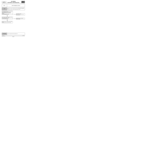
ALP 8 The volume does not change with a change in vehicle speed
NOTESOnly check the customer complaint after performing a full check with the diagnostic
tool.
Check that the customer is using the navigation system correctly.
Use the Wiring Diagrams Technical Note, Scenic II.
Check that volume according to speed function has
been activated.
Press the SET button and select the volume
correction menu.
Is the volume according to speed function
active?
YES
Carry out fault finding on the ABS/ESP (see 38C,
Anti-lock braking system).
Check the condition and connection of the receiver 32-track connector (component code 261) and of the navigation
computer 32-track connector (component code 662). If the connectors are faulty and if there is a repair method
(see Technical Note 6015A, Repairing electrical wiring, Wiring: Precautions for repair), repair
the connectors; otherwise, replace the wiring.
Check the insulation, continuity and the absence of interference resistance of the connection 47F between
components 261 and 662. If the connection is faulty and if there is a repair method (see Technical Note 6015A,
Repairing electrical wiring, Wiring: Precautions for repair), repair the wiring; otherwise, replace the wiring.
NOActivate this function.
Carry out a road test and check that
the volume varies as the vehicle speed
varies.
Does the volume vary?
NO YES
End of fault finding.
AFTER REPAIRCarry out a complete check with the diagnostic tool.
ITS_V04_ALP8ITSJ84ph2V1.0
Page 55 of 71
MULTIMEDIA
Fault finding - Fault finding charts
86C
86C-55V5 MR-372-J84-86C050$936.mif
ITS
Program No.: 0020
Vdiag No.: 04
ALP 8
CONTINUED
Check the condition and connection of the ABS computer connector (component code 118 or 1094). If the
connectors are faulty and if there is a repair method (see Technical Note 6015A, Repairing electrical wiring,
Wiring: Precautions for repair), repair the connectors; otherwise, replace the wiring.
If no fault is found with the ABS system, check the insulation, continuity and the absence of interference
resistance of connection 47F between components 261 and 118 or 1094 according to the vehicle's equipment
level.
If the connection is faulty and if there is a repair method (see Technical Note 6015A, Repairing electrical wiring,
Wiring: Precautions for repair), repair the wiring; otherwise, replace the wiring.
If the fault is still present, contact the Techline.
AFTER REPAIRCarry out a complete check with the diagnostic tool.
ITSJ84ph2V1.0
Page 56 of 71

MULTIMEDIA
Fault finding - Fault finding charts
86C
86C-56V5 MR-372-J84-86C050$936.mif
ITS
Program No.: 0020
Vdiag No.: 04
ALP 9 Poor radio reception
NOTESOnly check the customer complaint after performing a full check with the diagnostic
tool.
Use the Wiring Diagrams Technical Note, Scenic II.
Check the condition and connection of the 32-track connector and the aerial connector on the radio
(component code 886).
If the connectors are faulty and if there is a repair method (see Technical Note 6015A, Repairing electrical
wiring, Wiring: Precautions for repair), repair the connectors; otherwise, replace the wiring.
Check the insulation, continuity and the absence of interference resistance of the following connections:
●connection code 34AM,
●connection code 34AN,
●connection code TB13,
between components 261 and 886.
If any connection is faulty and if there is a repair method (see Technical Note 6015A, Repairing electrical wiring,
Wiring: Precautions for repair), repair the wiring; otherwise, replace the wiring.
If the fault is still present, contact the Techline.
AFTER REPAIRCarry out a complete check with the diagnostic tool.
ITS_V04_ALP9ITSJ84ph2V1.0