2008 RENAULT SCENIC fuses
[x] Cancel search: fusesPage 5 of 71

MULTIMEDIA
Fault finding - Introduction
86C
86C-5V5 MR-372-J84-86C050$052.mif
ITS
Program No.: 0020
Vdiag No.: 04
4. FAULT FINDING PROCEDURE (continued)
Wiring check
Fault finding problems
Disconnecting the connectors and/or handling the wiring harness may temporarily remove, the cause of a fault.
Electrical measurements of voltage, resistance and insulation are generally correct, especially if the fault is not
present when the analysis is made (stored fault).
Visual inspection
Look for damage under the bonnet and in the passenger compartment.
Carefully check the fuses, insulators and wiring harness routing.
Look for signs of oxidation.
Physical inspection
While manipulating the wiring harness, use the diagnostic tool to note any change in fault status from stored to
present.
Make sure that the connectors are properly locked.
Apply light pressure to the connectors.
Twist the wiring harness.
If there is a change in status, try to locate the source of the fault.
Inspection of each component
Disconnect the connectors and check the appearance of the clips and tabs, as well as the crimping (no crimping on
the insulating section).
Make sure that the clips and tabs are properly locked in the sockets.
Check that no clips or tabs have been dislodged during connection.
Check the clip contact pressure using an appropriate model of tab.
Resistance check
Check the continuity of entire lines, then section by section.
Look for a short circuit to earth, to + 12 V or with another wire.
If a fault is detected, repair or replace the wiring harness.
ITSJ84ph2V1.0
Page 45 of 71

MULTIMEDIA
Fault finding - Fault finding charts
86C
86C-45V5 MR-372-J84-86C050$936.mif
ITS
Program No.: 0020
Vdiag No.: 04MULTIMEDIA
Fault finding - Fault finding charts
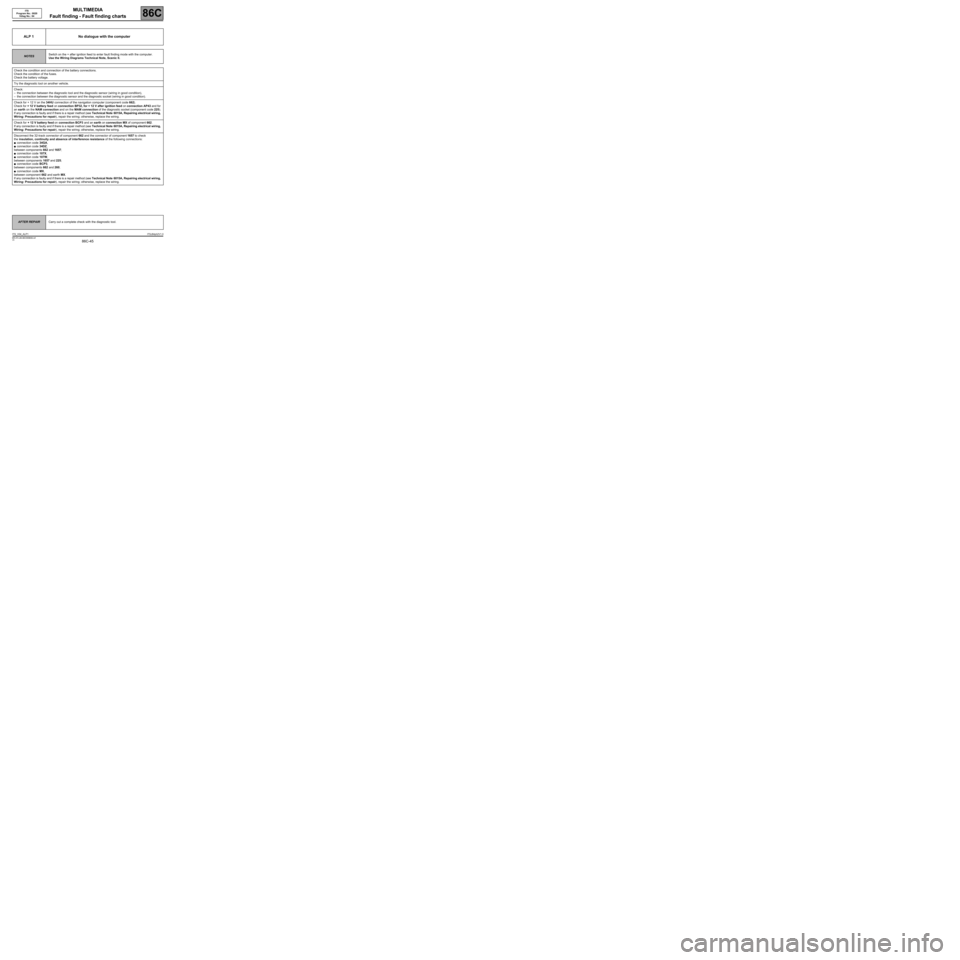
ALP 1 No dialogue with the computer
NOTESSwitch on the + after ignition feed to enter fault finding mode with the computer.
Use the Wiring Diagrams Technical Note, Scenic II.
Check the condition and connection of the battery connections.
Check the condition of the fuses.
Check the battery voltage.
Try the diagnostic tool on another vehicle.
Check:
–the connection between the diagnostic tool and the diagnostic sensor (wiring in good condition),
–the connection between the diagnostic sensor and the diagnostic socket (wiring in good condition).
Check for + 12 V on the 34HU connection of the navigation computer (component code 662).
Check for + 12 V battery feed on connection BP32, for + 12 V after ignition feed on connection AP43 and for
an earth on the NAM connection and on the MAM connection of the diagnostic socket (component code 225).
If any connection is faulty and if there is a repair method (see Technical Note 6015A, Repairing electrical wiring,
Wiring: Precautions for repair), repair the wiring; otherwise, replace the wiring.
Check for + 12 V battery feed on connection BCP3 and an earth on connection MX of component 662.
If any connection is faulty and if there is a repair method (see Technical Note 6015A, Repairing electrical wiring,
Wiring: Precautions for repair), repair the wiring; otherwise, replace the wiring.
Disconnect the 32-track connector of component 662 and the connector of component 1657 to check
the insulation, continuity and absence of interference resistance of the following connections:
●connection code 34GA,
●connection code 34DZ,
between components 662 and 1657;
●connection code 107X,
●connection code 107W,
between components 1657 and 225;
●connection code BCP3,
between components 662 and 260;
●connection code MX,
between component 662 and earth MX.
If any connection is faulty and if there is a repair method (see Technical Note 6015A, Repairing electrical wiring,
Wiring: Precautions for repair), repair the wiring; otherwise, replace the wiring.
AFTER REPAIRCarry out a complete check with the diagnostic tool.
ITS_V04_ALP1ITSJ84ph2V1.0
MR-372-J84-86C050$936.mif
Page 51 of 71

MULTIMEDIA
Fault finding - Fault finding charts
86C
86C-51V5 MR-372-J84-86C050$936.mif
ITS
Program No.: 0020
Vdiag No.: 04
ALP 6The radio does not switch on automatically or switches off after
20 minutes
NOTESOnly check the customer complaint after performing a full check with the diagnostic
tool.
Check that the customer is using the navigation system correctly.
Use the Wiring Diagrams Technical Note, Scenic II.
The navigation system does not receive the multimedia wake-up signal when the + after ignition feed is
switched on.
Check the condition of the CD changer fuses (component code 1272).
Has the fault disappeared?
NO YES
On pressing the CD changer on/off button, check for
the multimedia wake-up signal on connection 34HU
on the radio's blue connector (component
code 261).
Is the check result correct?
NO
Check the insulation, continuity and the absence
of interference resistance of connection 34HU
between components 1272, 261, 1657, 1127
and 662.
If any connection is faulty and if there is a repair
method (see Technical Note 6015A, Repairing
electrical wiring, Wiring: Precautions for repair),
repair the wiring; otherwise, replace the wiring.
Has the fault disappeared?
NO YES
End of fault finding.
End of fault finding.
YESCheck for + 12 V (+ battery feed) on
connection BCP3 of the component 261
black connector.
Is the check result correct?
NO YES
Check the insulation, continuity and the
absence of interference resistance of
connection BCP3 between components 261
and 260.
If any connection is faulty and if there is a repair
method (see Technical Note 6015A,
Repairing electrical wiring, Wiring:
Precautions for repair), repair the wiring;
otherwise, replace the wiring.
Has the fault disappeared?
YES NO
AFTER REPAIRCarry out a complete check with the diagnostic tool.
ITS_V04_ALP6ITSJ84ph2V1.0
Page 57 of 71

MULTIMEDIA
Fault finding - Fault finding charts
86C
86C-57V5 MR-372-J84-86C050$936.mif
ITS
Program No.: 0020
Vdiag No.: 04
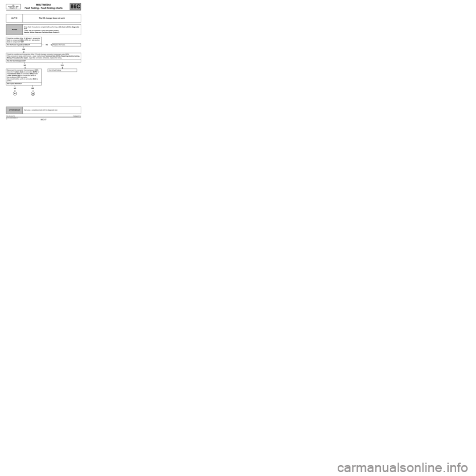
ALP 10 The CD changer does not work
NOTESOnly check the customer complaint after performing a full check with the diagnostic
tool.
Check that the customer is using the system properly.
Use the Wiring Diagrams Technical Note, Scenic II.
Check the condition of the 15 A fuses (+ accessories
feed) on component 260 and 7.5 A (+ after ignition
feed) on component 1337.
Are the fuses in good condition?
YES
Check the condition and connection of the CD multi-changer connector (component code 1272).
If the connector is faulty and if there is a repair method (see Technical Note 6015A, Repairing electrical wiring,
Wiring: Precautions for repair), repair the connector; otherwise, replace the wiring.
Has the fault disappeared?
NO YES
Disconnect the connector from component 1272,
check for + battery feed on connection BCP3, for
+ accessories feed on connection SP2 and for
+ after ignition feed on connection AP43 of
the component 1272 connector.
Also check that the earth on connection MAN is
perfect.
Did it pass the tests?
NO YES
NOReplace the fuses.
End of fault finding.
AFTER REPAIRCarry out a complete check with the diagnostic tool.
ITS_V04_ALP10ITSJ84ph2V1.0