Page 41 of 107

17C-41
MR-372-J84-17C000$354.mif
V2
GAS INJECTION
Fault finding - Interpretation of faults
LPG 3000
Program No: AB
Vdiag No: 08/10
17C
DF087
PRESENT
OR
STOREDCYLINDER 4 INJECTOR CIRCUIT
CO.0: Open circuit or short circuit to earth
CC.1: Short circuit to + 12 Volts
1.DEF: Non-compliance with emission control standards
IMPORTANT
When carrying out an operation on an LPG supply circuit component, consult the safety instructions
(see 17D, Gas injection, Introduction, Safety instructions for all operations).
NOTESPriority when dealing with a number of faults:
If fault DF021 LPG tank solenoid valve relay circuit is present or stored, deal with
this fault first.
Conditions for applying the fault finding procedure to stored faults:
The fault is declared present after the engine is started and switched to LPG mode
or when command AC018 Cylinder 4 injector is executed.
Manipulate the wiring harness between the LPG computer and Injector number 4 to produce a change in status.
(present ↔ stored).
Look for any harness damage, and check the condition and connection of injector no. 4 and its connectors.
If necessary, repair or replace the connector.
Measure the resistance of injector 4 between tracks 1 and 2.
The injector resistance value at approximately 20°C should be between:
0.7 Ω < R < 1.45 Ω
Replace the injector if necessary.
Check for insulation against earth, continuity and absence of interference resistance for the following
connections:
For Mégane 2:
General relay track 5
Black intermediate connector (R37) track 8
LPG Computer track H3
Black intermediate connector (R37) track 4
For Logan:
Injector 4 track 1
LPG Computer track H3track 8 of the black intermediate connector (R37)
track 1of injector 4
track 4 of the black intermediate connector (R37)
track 2 of injector 4
track A1 of the double control relay unit
track 2 of injector 4
Repair if necessary.
AFTER REPAIRDeal with any faults displayed by the diagnostic tool.
Clear the computer memory.
Carry out a road test followed by another check with the diagnostic tool.
GAZ3000_V08_DF087 / GAZ3000_V10_DF087
Page 42 of 107
17C-42
MR-372-J84-17C000$354.mif
V2
GAS INJECTION
Fault finding - Interpretation of faults
LPG 3000
Program No: AB
Vdiag No: 08/10
17C
DF087
CONTINUED
With the ignition on,
–check for + 12V on track 1 of injector 4,
–check for earth on track 2 of injector 4 when command AC018 Cylinder 4 injector is run.
Repair if necessary.
If the fault is still present, contact the Techline.
AFTER REPAIRDeal with any faults displayed by the diagnostic tool.
Clear the computer memory.
Carry out a road test followed by another check with the diagnostic tool.
Page 43 of 107

17C-43
MR-372-J84-17C000$354.mif
V2
GAS INJECTION
Fault finding - Interpretation of faults
LPG 3000
Program No: AB
Vdiag No: 08/10
17C
DF088
PRESENT
OR
STOREDCYLINDER 3 INJECTOR CIRCUIT
CO.0: Open circuit or short circuit to earth
CC.1: Short circuit to + 12 Volts
1.DEF: Non-compliance with emission control standards
IMPORTANT
When carrying out an operation on an LPG supply circuit component, consult the safety instructions
(see 17D, Gas injection, Introduction, Safety instructions for all operations).
NOTESPriority when dealing with a number of faults:
If fault DF021 LPG tank solenoid valve relay circuit is present or stored, deal with
this fault first.
Conditions for applying the fault finding procedure to stored faults:
The fault is declared present after the engine is started and switched to LPG mode
or when command AC019 Cylinder 3 injector is executed.
Manipulate the wiring harness between the LPG computer and Injector number 3 to produce a change in status.
(present ↔ stored).
Look for any damage to the wiring harness and check the connection and condition of the injector and its
connections.
If necessary, repair or replace the connector.
Measure the resistance of injector 3 between tracks 1 and 2.
The injector resistance value at approximately 20°C should be between:
0.7 Ω < R < 1.45 Ω
Replace the injector if necessary.
Check for insulation against earth, continuity and absence of interference resistance for the following
connections:
For Mégane 2:
General relay track 5
Black intermediate connector (R37) track 7
LPG computer track H2
Black intermediate connector (R37) track 3
For Logan:
Injector 3 track 1
LPG computer track H2track 7 of the black intermediate connector (R37)
track 1of injector 3
track 3 of the black intermediate connector
track 2 of injector 3
track A1 of the double control relay unit
track 2 of injector 3
Repair if necessary.
AFTER REPAIRDeal with any faults displayed by the diagnostic tool.
Clear the computer memory.
Carry out a road test followed by another check with the diagnostic tool.
GAZ3000_V08_DF088 / GAZ3000_V10_DF088
Page 44 of 107
17C-44
MR-372-J84-17C000$354.mif
V2
GAS INJECTION
Fault finding - Interpretation of faults
LPG 3000
Program No: AB
Vdiag No: 08/10
17C
DF088
CONTINUED
With the ignition on,
–check for + 12V on track 1 of injector 3,
–check for earth on track 2 of injector 3 when command AC019 Cylinder 3 injector is run.
Repair if necessary.
If the fault is still present, contact the Techline.
AFTER REPAIRDeal with any faults displayed by the diagnostic tool.
Clear the computer memory.
Carry out a road test followed by another check with the diagnostic tool.
Page 45 of 107

17C-45
MR-372-J84-17C000$354.mif
V2
GAS INJECTION
Fault finding - Interpretation of faults
LPG 3000
Program No: AB
Vdiag No: 08/10
17C
DF092
PRESENT
OR
STOREDLPG PRESSURE SENSOR DOWNSTREAM OF EXPANSION VALVE
CO.0: Short circuit to earth
CC.1: Open circuit or short circuit to + 12V
1.DEF: Non-compliance with emission control standards
NOTESFault finding procedure application conditions:
Present or stored fault.
Manipulate the wiring harness between the LPG computer and the LPG pressure/temperature sensor in order to
produce a change in status (present ↔ stored).
Look for any damage to the wiring harness and check the connection and condition of the LPG pressure/
temperature sensor and its connections.
If necessary, repair or replace the connector.
Check for + 5V on track 1 (for Mégane 2) or track 3 (for Logan) of the LPG pressure/temperature sensor in LPG
mode.
Check the insulation in relation to earth and the continuity and the absence of interference resistance on
the connection between:
For Mégane 2:
LPG computer track A3
For Logan:
LPG computer track A3track 1 of the LPG temperature/pressure sensor
track 3 of the LPG temperature/pressure sensor
Repair if necessary.
Check for earth on tracks 3 and 1 of the LPG pressure/temperature sensor in LPG mode.
Check the insulation in relation to + 12V and the continuity and absence of interference resistance on
the connection between:
For Mégane 2:
LPG computer track B3
For Logan:
LPG computer track B3track 3 of the LPG temperature/pressure sensor
track 1 of the LPG temperature/pressure sensor
Repair if necessary.
Check the insulation, continuity and the absence of interference resistance on the connection between:
For Mégane 2:
LPG computer track C4
For Logan:
LPG computer track E2track 2 of the LPG pressure/temperature sensor
track 2 of the LPG pressure/temperature sensor
Repair if necessary.
AFTER REPAIRDeal with any faults displayed by the diagnostic tool.
Clear the computer memory.
Carry out a road test followed by another check with the diagnostic tool.
GAZ3000_V08_DF092 / GAZ3000_V10_DF092
Page 46 of 107
17C-46
MR-372-J84-17C000$354.mif
V2
GAS INJECTION
Fault finding - Interpretation of faults
LPG 3000
Program No: AB
Vdiag No: 08/10
17C
DF092
CONTINUED
Replace the sensor if the pressure is no more than 0.8 bar greater than the manifold pressure PR001 Manifold
pressure.
Check the manifold pressure sensor sealing.
Check the pressure value using parameters PR001 Manifold pressure, PR003 Pressure difference:
LPG/manifold and PR112 LPG pressure downstream of expansion valve and ensure that
PR003 = PR112 - PR001.
If the fault is still present, deal with the other faults, then proceed to the conformity check.
AFTER REPAIRDeal with any faults displayed by the diagnostic tool.
Clear the computer memory.
Carry out a road test followed by another check with the diagnostic tool.
Page 47 of 107

17C-47
MR-372-J84-17C000$413.mif
V2
17C
GAS INJECTION
Fault finding - Interpretation of faults
DF095
PRESENT
OR
STOREDLPG TEMPERATURE SENSOR CIRCUIT
1.DEF : Signal outside lower limit
2.DEF : Signal outside upper limit
3.DEF : Non-compliance with emission control standards
IMPORTANT
Before working on an LPG supply circuit component, always refer to the appropriate section of the
Workshop Repair Manual (see 17D, LPG Injection, Introduction, Safety advice for all operations).
NOTESConditions for applying the fault finding procedure to stored faults:
–The fault is declared present after the engine has been started and switched to LPG
mode.
Manipulate the wiring harness between the LPG computer and the LPG temperature/pressure sensor in order to
produce a change in status (present to stored).
Look for any damage to the harness, and check the connection and condition of the LPG pressure/temperature
sensor and its connectors.
If necessary, repair or replace the connector.
Check for + 5 V on track 3 of the LPG pressure/temperature sensor in LPG mode.
Check the following connections for insulation from earth, continuity and absence of extraneous resistance:
LPG computer track A3 track 3 of the LPG pressure/temperature sensor
Repair if necessary.
Check for earth on track 1 of the LPG pressure/temperature sensor in LPG mode.
Check the following connections for insulation from +5 V, continuity and absence of extraneous resistance:
LPG computer track B3 track 1 of the LPG pressure/temperature sensor
Repair if necessary.
Check the insulation, the continuity and absence of unwanted resistance on the connection between:
LPG computer track E2 track 2 of the LPG pressure/temperature sensor
Repair if necessary.
Measure the resistance of the temperature sensor.
Replace the sensor if the resistance is not: 2.5 kΩ ± 0.1 kΩ at 20 ˚C
1.2 kΩ ± 0.1 Ω at 40 ˚C
If the fault is still present, deal with the other faults, then proceed to the conformity check.
AFTER REPAIRDeal with any faults displayed by the diagnostic tool.
Clear the computer memory.
Carry out a road test followed by another check with the diagnostic tool.
GAZ3000_V08_DF095 / GAZ3000_V10_DF095
LPG 3000
Program No: AB
Vdiag No: 08/10
MR-372-J84-17C000$413.mif
Page 48 of 107

17C-48
MR-372-J84-17C000$413.mif
V2
GAS INJECTION
Fault finding - Interpretation of faults
LPG 3000
Program No: AB
Vdiag No: 08/10
17C
DF096
PRESENT
OR
STOREDSENSOR SUPPLY VOLTAGE
1.DEF : Voltage outside permitted range of values
2.DEF : Non-compliance with emission control standards
NOTESConditions for applying the fault finding procedure to stored faults:
The fault is declared present after the engine has been running for 10 seconds in
LPG mode.
Manipulate the wiring harness between the LPG computer and the LPG temperature/ pressure sensor in order to
produce a change in status (present ↔ stored).
Look for any damage to the harness, and check the connection and condition of the LPG pressure/temperature
sensor and its connectors.
If necessary, repair or replace the connector.
Check for + 5 V on track A4 and A3 (for Mégane 2) and on track B2 and A3 (for Logan) and for earth on
track B3 and D3 (for Mégane 2) or tracks G1 and H1 (for Logan) of the LPG computer.
Repair if necessary.
If incorrect, contact the Techline.
Check for a supply on tracks A3 and A4 of the LPG computer.
The voltage value must be between:
4.8 < V < 5.2
Check the insulation and continuity of the following connections:
For Mégane 2:
LPG computer track A4
LPG computer track A3
For Logan:
LPG computer track B2
LPG computer track A3track B of the LPG tank sender
track 1 of the LPG pressure sensor
track A2 of the LPG tank sender
track 3 of the LPG pressure sensor
Repair if necessary.
If the fault is still present, deal with the other faults, then proceed to the conformity check.
AFTER REPAIRDeal with any faults displayed by the diagnostic tool.
Clear the computer memory.
Carry out a road test followed by another check with the diagnostic tool.
GAZ3000_V08_DF096 / GAZ3000_V10_DF096
 1
1 2
2 3
3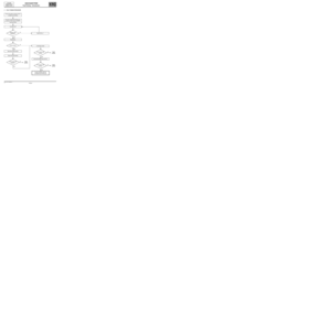 4
4 5
5 6
6 7
7 8
8 9
9 10
10 11
11 12
12 13
13 14
14 15
15 16
16 17
17 18
18 19
19 20
20 21
21 22
22 23
23 24
24 25
25 26
26 27
27 28
28 29
29 30
30 31
31 32
32 33
33 34
34 35
35 36
36 37
37 38
38 39
39 40
40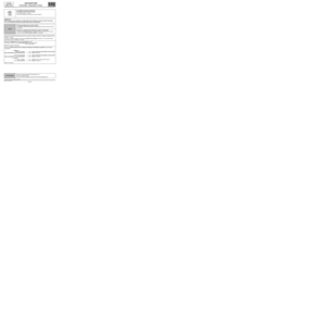 41
41 42
42 43
43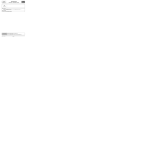 44
44 45
45 46
46 47
47 48
48 49
49 50
50 51
51 52
52 53
53 54
54 55
55 56
56 57
57 58
58 59
59 60
60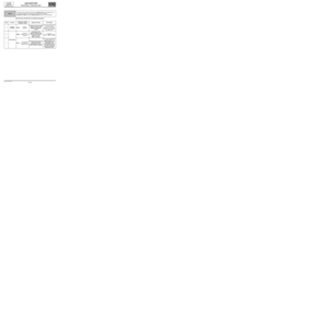 61
61 62
62 63
63 64
64 65
65 66
66 67
67 68
68 69
69 70
70 71
71 72
72 73
73 74
74 75
75 76
76 77
77 78
78 79
79 80
80 81
81 82
82 83
83 84
84 85
85 86
86 87
87 88
88 89
89 90
90 91
91 92
92 93
93 94
94 95
95 96
96 97
97 98
98 99
99 100
100 101
101 102
102 103
103 104
104 105
105 106
106

