Page 9 of 107

17C-9
MR-372-J84-17C000$118.mif
V2
17C
GAS INJECTION
Fault finding - System operation
1. System operation:
Composition
–The LPG injection system consists of the:
–LPG tank,
–fuel sender,
–overpressure unit (thermally triggered),
–LPG solenoid valve relay,
–tank solenoid valve,
–reducer (LPG) or expansion valve (CNG),
–expansion valve,
–filling spigot or socket,
–LPG hose,
–tank pressure sensor,
–LPG pipes,
–unions,
–airtight cover,
–regulator valve or anti-return valve,
–excess pressure valve,
–LPG filter,
–temperature and pressure sensor,
–LPG computer,
–LPG expansion solenoid valve,
–gas injectors,
–LPG or petrol selection switch,
–fuel sender relay,
–LPG tank relay,
–fuel pump cut-off relay.
Operating principle
The GAS 3000 computer electronically manages the operation of the LPG systems (Liquefied Petroleum Gas) and
CNG (Compressed Natural Gas).
The engine must be started in Petrol mode. The vehicle will automatically switch to "Gas" mode after starting if the
"gas" configuration was selected beforehand. "Petrol" mode switches to "gas" mode after a certain time delay, which
depends on the engine coolant temperature.
Petrol mode operates autonomously. Information is shared between the Petrol computer and the LPG computer via
a CAN connection.
The K line shared by the two computers allows diagnostics to be run on both the petrol and the LPG systems.
The Petrol computer is also the supervisor of the LPG system and includes, in addition to petrol-specific functions,
functions for adapting engine management programming to LPG operation.
Therefore, the Petrol computer includes settings and variables that are specific for LPG operation, e.g. ignition
advance adjustment in LPG mode, LPG flow rate setting, richness regulation, engine operating mode, etc.
It controls the choice of program (petrol start-up etc.) and controls the transition phases for switching from one
operating mode to the other: Petrol → Gas or Gas → Petrol. The fuel pump is regularly supplied to keep the system
under pressure in the event of a possible return to "Petrol" mode (if the "Gas" tank is detected as empty or if a fault
is detected).
LPG 3000
Program No: AB
Vdiag No: 08/10
MR-372-J84-17C000$118.mif
Page 10 of 107

17C-10
MR-372-J84-17C000$118.mif
V2
GAS INJECTION
Fault finding - System operation
LPG 3000
Program No: AB
Vdiag No: 08/10
17C
The GAS 3000 computer manages "gas" actuator control, i.e. the "gas" injectors, the gas system relays and solenoid
valves, the fuel pump cut-off relay and the management of the fuel sender. Before switching to "Gas" mode, the
computer always checks that the pressure and the temperature of the gas are correct and that the "gas" solenoid
valves are open.
The combustible material is stored in an independent toric tank. LPG is stored in a semi-gaseous state at a pressure
of approximately 15 bar.
CNG is stored in a cylindrical tank in a gaseous state at a pressure of approximately 200 bar, and is transported to
the expansion valve/reducer via a rigid high pressure pipe. The rest of the system is a low pressure pipe going from
the expansion valve/reducer to the injectors. For CNG, there is a gas filter between the expansion valve and the rail.
Malfunctions / Special cases
These are characterised by operation in Petrol mode, although the driver has selected LPG mode.
An operational fault must be caused by the LPG system if it cannot be reproduced in Petrol mode.
Forced Petrol mode when LPG is faulty.
The level 1 warning light is controlled by the petrol injection computer; the gas warning light is controlled by the GAS
3000 computer.
The system automatically switches to "petrol" mode when the tank is empty or when the conditions allowing
operation in "gas" mode are not satisfied.
Page 11 of 107
:
–Purpose:
–It enables the pressure of the gas")
17C-11
MR-372-J84-17C000$118.mif
V2
GAS INJECTION
Fault finding - System operation
LPG 3000
Program No: AB
Vdiag No: 08/10
17C
Expansion valve (CNG):
–Purpose:
–It enables the pressure of the gas from the tank to be lowered to a value which is compatible with the injection
system (injectors and temperature pressure sensor downstream from the expansion valve).
–The gas pressure is approximately 3 bar at the expansion valve outlet.
–It regulates the pressure in the injector rail to the pressure in the manifold.
Reducer (LPG):
– Purpose:
–It has the same functions as the expansion valve. Furthermore, it ensures that the fuel switches from a liquid state
to a gaseous state (the gas pressure is approximately 2 bar at the reducer output).
–Operation:
The LPG expansion valve and the CNG reducer are essential components and are composed of:
●a stage for lowering the pressure from 25 bar maximum to a pressure in line with the manifold pressure,
P
output = Pmanifold + 0.85 bars (LPG)
Poutput = Pmanifold + 1.8 bars (CNG with 100 bar of pressure in the tank)
●a pressure regulator, comprised of a system of valves, springs and diaphragms,
●a cut-off solenoid valve,
●a water heating system.
–The expansion solenoid valve
This component controls only supply of gas to the expansion valve. Controlled by the computer, the solenoid valve
allows LPG into the two stages of the expansion valve, thus supplying the LPG injectors.
2. Intersystem connections:
Connections to the other computers:
–Petrol injection computer,
–protection and switching unit
–instrument panel.
Page 12 of 107
17C-12
MR-372-J84-17C000$118.mif
V2
GAS INJECTION
Fault finding - System operation
LPG 3000
Program No: AB
Vdiag No: 08/10
17C
Sender and LPG indicator light programming:
–LPG indicator light:
–Sender indicator light:
Pressing the button determines which gauge is displayed ("petrol" level or "gas" level).
Illumination of the warning light for minimum gauge level depends only on the actual level of fuel in the tank.Note:
Before carrying out any work on the LPG system, check that the vehicle operates correctly in Petrol
mode.
LPG indicator light status
Operating mode Megane 2 Logan
Petrol Off Off
Forced petrol due to LPG condition Steady green Off
Forced Petrol mode when LPG is faulty Amber Permanent flashing green
Forced Petrol mode for empty LPG tank Flashing greenFlashing green
(timed: 16-second)
Gas Steady green Steady green
Petrol to LPG Transition Steady green Steady green
LPG to Petrol Transition Steady green Off
Page 13 of 107

17C-13
MR-372-J84-17C000$177.mif
V2
17C
GAS INJECTION
Fault finding - Replacement of components
COMPUTER REPLACEMENT OR REPROGRAMMING PROCEDURE
The system can be programmed and reprogrammed via the diagnostic socket using the RENAULT CLIP diagnostic
tool (see Technical Note 3585A or follow the instructions provided by the diagnostic tool).
After reprogramming or replacing the computer:
–Switch the ignition off and then on again.
–Start and run the engine in LPG mode then stop the engine (to initialise the computer) and wait for
30 seconds.
–Switch on the ignition and use the diagnostic tool to carry out the following steps:
–use command VP001 Write VIN,
–after the injection has been reprogrammed, stored faults may appear on other computers. Clear the memories of
these computers,
–carry out a road test followed by another check with the diagnostic tool. IMPORTANT
–switch on the diagnostic tool (mains or cigarette lighter supply),
–connect a battery charger,
–shut down all the electrical consumers (lights, interior lights, air conditioning, radio CD, etc.),
–wait for the engine to cool down (coolant temperature below 60 °C and air temperature below 50 °C).
LPG 3000
Program No: AB
Vdiag No: 08/10
MR-372-J84-17C000$177.mif
Page 14 of 107
17C-14
MR-372-J84-17C000$236.mif
V2
17C
GAS INJECTION
Fault finding - Configurations and programming
1. CONFIGURATION
CF LC010LPG downstream temperature sensor
WITH
NONE→ CNG
→ LPG
CF LC011LPG downstream pressure sensor
NONE
SAGEMJ/JCAE
BOSCH→ LPG
→ CNG
LPG 3000
Program No: AB
Vdiag No: 08/10
MR-372-J84-17C000$236.mif
Page 15 of 107

17C-15
MR-372-J84-17C000$295.mif
V2
17C
GAS INJECTION
Fault finding - Fault summary table
Tool fault Associated DTC Description
DF0032617 Engine speed inconsistency
DF0071B47 Main relay circuit
DF0131B40 Tank solenoid valve circuit
DF0141B42 Gauge supply circuit
DF0161685 Impact detected
DF0171094 LPG leak detection downstream of expansion valve
DF0180512 + after ignition feed
DF0191B05 LPG pressure sensor circuit
DF0201B45 Fuel sender switching relay circuit
DF0211B46 LPG tank solenoid valve relay circuit
DF0221B60 Computer
DF0241B43 Fuel pump cut-off relay circuit
DF026C073 Multiplex network
DF0291B20 LPG tank sender signal voltage
DF0300657 LPG tank sender supply voltage
DF0311B61 LPG pressure downstream from expansion valve
DF061C100 Multiplex network
DF0740336 TDC signal circuit
DF0800560 Battery voltage
DF0811B32 Cylinder 2 injector circuit
DF0831B00 LPG pressure sensor circuit
DF0871B34 Cylinder 4 injector circuit
DF0881B33 Cylinder 3 injector circuit
DF0921B05 Expansion valve downstream LPG pressure sensor circuit
DF0951B10 LPG temperature sensor circuit
DF0960641 Sensor supply voltage
DF0981B31 Cylinder 1 injector circuit
DF0991B49 Instrument panel indicator circuit
DF1031B41 LPG expansion valve solenoid valve circuit
LPG 3000
Program No: AB
Vdiag No: 08/10
MR-372-J84-17C000$295.mif
Page 16 of 107

17C-16
MR-372-J84-17C000$354.mif
V2
17C
GAS INJECTION
Fault finding - Interpretation of faults
DF003
PRESENT
OR
STOREDENGINE SPEED CONSISTENCY
1.DEF: Signal incoherent
2.DEF: Non-compliance with emission control standards
NOTESConditions for applying fault finding procedures to stored faults:
The fault is declared present after the engine has been running for 10 seconds in
LPG mode.
Appearance conditions:
The fault appears when the difference between the hard-wired petrol computer engine
speed signal and the multiplex network engine speed is greater than 300 rpm.
Manipulate the wiring between the LPG computer and the petrol computer in order to produce a change in status
(present ↔ stored).
Look for any damage to the wiring harness and check the connection and condition of the LPG computer and its
connections and carry out the same checks on the injection computer.
Repair if necessary.
Check the insulation and continuity on the wires of the following multiplex connections:
For Mégane 2:
LPG computer track A1
LPG computer track A2
For Logan:
LPG computer track A1
LPG computer track A2track K3, connector B, petrol computer
track K4, connector B, petrol computer
track 25 of the petrol computer
track 26 of the petrol computer
Repair if necessary.
Check the insulation, continuity and the absence of interference resistance on the connection between:
LPG computer track F1 track C3, connector B, of the petrol computer
Repair if necessary.
If the fault is still present, deal with the other faults, then proceed to the conformity check.
AFTER REPAIRDeal with any faults displayed by the diagnostic tool.
Clear the computer memory.
Carry out a road test followed by another check with the diagnostic tool.
GAZ3000_V08_DF003 / GAZ3000_V10_DF003
LPG 3000
Program No: AB
Vdiag No: 08/10
MR-372-J84-17C000$354.mif
 1
1 2
2 3
3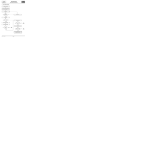 4
4 5
5 6
6 7
7 8
8 9
9 10
10 11
11 12
12 13
13 14
14 15
15 16
16 17
17 18
18 19
19 20
20 21
21 22
22 23
23 24
24 25
25 26
26 27
27 28
28 29
29 30
30 31
31 32
32 33
33 34
34 35
35 36
36 37
37 38
38 39
39 40
40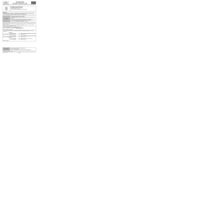 41
41 42
42 43
43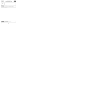 44
44 45
45 46
46 47
47 48
48 49
49 50
50 51
51 52
52 53
53 54
54 55
55 56
56 57
57 58
58 59
59 60
60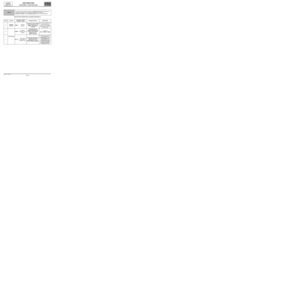 61
61 62
62 63
63 64
64 65
65 66
66 67
67 68
68 69
69 70
70 71
71 72
72 73
73 74
74 75
75 76
76 77
77 78
78 79
79 80
80 81
81 82
82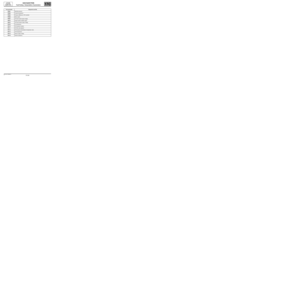 83
83 84
84 85
85 86
86 87
87 88
88 89
89 90
90 91
91 92
92 93
93 94
94 95
95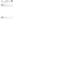 96
96 97
97 98
98 99
99 100
100 101
101 102
102 103
103 104
104 105
105 106
106
