Page 17 of 107

17C-17
MR-372-J84-17C000$354.mif
V2
GAS INJECTION
Fault finding - Interpretation of faults
LPG 3000
Program No: AB
Vdiag No: 08/10
17C
DF007
PRESENT
OR
STOREDMAIN RELAY CIRCUIT
1.DEF: Voltage outside permitted range of values
2.DEF: Non-compliance with emission control standards
NOTESConditions for applying the fault finding procedure to stored faults:
The fault is declared present after the engine has been started and switched to LPG
mode.
Manipulate the wiring harness between the LPG computer and the main relay in order to produce a change in
status.
Look for any damage to the wiring harness and check the connection and condition of the main relay and its
connections (present ↔ stored).
If necessary, repair or replace the connector.
With the ignition on, check for +12V on track 1 and track 3 of the main relay.
If no + 12 V:
–disconnect the battery,
–in the Protection and Switching Unit, disconnect the grey connector,
–check the cleanliness and condition of the connections,
–Use the universal bornier to check the continuity of the following connection:
For Mégane 2:
Protection and Switching Unit, grey connector, track 1
For Logan:
Fuse box, track S4track 3 of the main relay
track A5 of the main relay
Repair if necessary.
Check the insulation in relation to + 12V and the continuity and absence of interference resistance on
the connection between:
LPG computer track F4 track 2 of the main relay
Repair if necessary.
With the ignition on, check for earth on track 2 of the main relay.
If, with the ignition on, the computer does not control the main relay on track 2 via an earth, contact the Techline.
With the engine running, check that the relay clicks when LPG mode is selected.
Replace the main relay if necessary.
If the fault is still present, deal with the other faults, then proceed to the conformity check.
AFTER REPAIRDeal with any faults displayed by the diagnostic tool.
Clear the computer memory.
Carry out a road test followed by another check with the diagnostic tool.
GAZ3000_V08_DF007 / GAZ3000_V10_DF007
Page 18 of 107

17C-18
MR-372-J84-17C000$354.mif
V2
GAS INJECTION
Fault finding - Interpretation of faults
LPG 3000
Program No: AB
Vdiag No: 08/10
17C
DF013
PRESENT
OR
STOREDTANK SOLENOID VALVE CIRCUIT
CC.1: Short circuit to + 12 Volts
1.DEF: Non-compliance with emission control standards
IMPORTANT
When carrying out an operation on an LPG supply circuit component, consult the safety instructions
(see 17D, Gas injection, Introduction, Safety instructions for all operations).
NOTESPriority when dealing with a number of faults:
If fault DF021 LPG tank solenoid valve relay circuit or fault DF018 + After ignition
feed supply or fault DF016 Impact detected are present or stored, deal with these
faults first.
Conditions for applying the fault finding procedure to stored faults:
The fault is declared present after the engine is started and switched to LPG mode
or when command AC015 Tank solenoid valve is executed.
Manipulate the wiring harness between the gas computer and the gas tank solenoid valves in order to produce
a change in status (present ↔ stored).
Look for any damage to the wiring harness and check the connection and condition of the LPG tank solenoid
valves and their connections.
Repair if necessary.
Check the connection and condition of the LPG tank solenoid valve relay connector and its connections.
Replace the connector if necessary.
–check that the solenoid valve is supplied with +12V via track E3 of the LPG computer.
–check for + 12V on track D (for Mégane 2) or on track A (for Logan) of the LPG tank solenoid valve.
If necessary, check the insulation to earth and the continuity and absence of interference resistance on
the following connections:
For Mégane 2:
LPG tank solenoid valve track D
For Logan:
LPG tank solenoid valve track Atrack B5 of the LPG tank solenoid valve relay
track E3, LPG computer
track B5 of the LPG tank solenoid valve relay
track E3, LPG computer
If the fault is still present, check the intermediate connectors (R2 track 38, for Mégane 2), (R34 track 9,
for Logan).
Repair if necessary.
AFTER REPAIRDeal with any faults displayed by the diagnostic tool.
Clear the computer memory.
Carry out a road test followed by another check with the diagnostic tool.
GAZ3000_V08_DF013 / GAZ3000_V10_DF013
Page 19 of 107
 or")
17C-19
MR-372-J84-17C000$354.mif
V2
GAS INJECTION
Fault finding - Interpretation of faults
LPG 3000
Program No: AB
Vdiag No: 08/10
17C
DF013
CONTINUED
Check for earth on track E (for Mégane 2) or on track B (for Logan) of the LPG tank solenoid valve.
Repair if necessary.
With the engine running, check that the LPG tank solenoid valve relay clicks when LPG mode is selected.
If the fault is still present, check the insulation in relation to +12 V and the continuity and absence
of interference resistance on the following connections:
LPG computer track E4 track 2 of the LPG tank solenoid valve relay
Repair if necessary.
With the ignition on, check for + 12 volts on track C2 of the LPG computer.
Check the insulation in relation to + 12V and the continuity and absence of interference resistance on
the connection between:
LPG computer track C2 track 1 of the LPG tank solenoid valve relay
Repair if necessary.
With the ignition on, check that the relay and the fuel pump are supplied with + 12V.
Check the insulation in relation to + 12V and the continuity and absence of interference resistance on
the connection between:
For Mégane 2:
Fuel pump relay track 2
For Logan:
Fuel pump relay track B5track 3 of the LPG tank solenoid valve relay
track 3 of the LPG tank solenoid valve relay
Repair if necessary.
If the fault is still present, deal with the other faults, then proceed to the conformity check.
AFTER REPAIRDeal with any faults displayed by the diagnostic tool.
Clear the computer memory.
Carry out a road test followed by another check with the diagnostic tool.
Page 20 of 107
17C-20
MR-372-J84-17C000$354.mif
V2
GAS INJECTION
Fault finding - Interpretation of faults
LPG 3000
Program No: AB
Vdiag No: 08/10
17C
DF014
PRESENT
OR
STOREDGAUGE SUPPLY CIRCUIT
CC.0: Open circuit or short circuit to earth
CC.1: Short circuit to + 12 volts
NOTESSpecial note:
The system changes to forced petrol mode "LPG system fault" and refuses to change
to LPG mode while the fault is present.
Clear the faults from memory and then start the engine.
If the fault is still present, contact the Techline.
AFTER REPAIRDeal with any faults displayed by the diagnostic tool.
Clear the computer memory.
Carry out a road test followed by another check with the diagnostic tool.
GAZ3000_V08_DF014 / GAZ3000_V10_DF014
Page 21 of 107

17C-21
MR-372-J84-17C000$354.mif
V2
GAS INJECTION
Fault finding - Interpretation of faults
LPG 3000
Program No: AB
Vdiag No: 08/10
17C
DF016
PRESENT
IMPACT DETECTED
1.DEF: Impact detected
2.DEF: Non-compliance with emission control standards
NOTESPriority when dealing with a number of faults:
If faults DF021 LPG tank solenoid valve relay circuit or fault DF018 + After ignition
feed supply are present or stored, deal with these faults first.
Special note:
As soon as the LPG computer receives this signal, engine operation is prohibited.
If the vehicle has been involved in an accident:
Carry out any necessary repairs,
–clear the fault,
–switch off the ignition,
–wait for the engine immobiliser indicator light to flash,
–switch on the ignition,
If the fault does not recur, end the fault finding procedure.
If the fault recurs, carry out fault finding on the AIRBAG computer.
If the vehicle has not been involved in an accident:
Check for + 12V on track 3 of the fuel pump cut-off relay and the LPG tank relay.
Repair if necessary.
AFTER REPAIRDeal with any faults displayed by the diagnostic tool.
Clear the computer memory.
Carry out a road test followed by another check with the diagnostic tool.
GAZ3000_V08_DF016P / GAZ3000_V10_DF016
Page 22 of 107

17C-22
MR-372-J84-17C000$354.mif
V2
GAS INJECTION
Fault finding - Interpretation of faults
LPG 3000
Program No: AB
Vdiag No: 08/10
17C
DF017
PRESENT
OR
STOREDLPG LEAK DETECTION DOWNSTREAM OF THE EXPANSION
VALVE
1.DEF: Leak detection
2.DEF: Non-compliance with emission control standards
IMPORTANT
When carrying out an operation on an LPG supply circuit component, consult the safety instructions
(see 17D, Gas injection, Introduction, Safety instructions for all operations).
NOTESFault finding procedure application conditions:
–clear the faults,
–start the engine,
–select LPG mode,
–wait for the engine to operate in LPG mode with the status ET093 LPG mode
set to YES,
–turn the engine off,
–wait for 5 minutes,
–confirm that the fault is present.
Special note:
To detect the leak, use the product distributed by SODICAM, available under Part
number 77 11 143 071 (leak detector).
Start the engine and select LPG mode. Wait for the engine to operate in LPG mode with the status ET093 LPG
Mode set to YES and apply the leak detector product to:
–the expansion valve,
–the pipe between the expansion valve and the injector rail,
–the pipes between the injector rail and the injectors,
–the injector bodies.
Repair if necessary.
With the ignition on and the engine off, control the expansion valve solenoid valve using command
AC024 Expansion valve solenoid valve.
Without disconnecting the pipes, carefully remove:
–the LPG injector rail,
–the LPG injectors.
Apply the leak detector product to the injector seats.
Replace the faulty injector(s) (see MR 364 Mechanical, 17D, Gas injection, Injectors).
If the fault is still present, contact the Techline.
AFTER REPAIRDeal with any faults displayed by the diagnostic tool.
Clear the computer memory.
Carry out a road test followed by another check with the diagnostic tool.
GAZ3000_V08_DF017 / GAZ3000_V10_DF017
Page 23 of 107

17C-23
MR-372-J84-17C000$354.mif
V2
GAS INJECTION
Fault finding - Interpretation of faults
LPG 3000
Program No: AB
Vdiag No: 08/10
17C
DF018
PRESENT
OR
STORED+ AFTER IGNITION SUPPLY
CC.1: Short circuit to + 12 Volts
1.DEF: Abnormal voltage
2.DEF: Non-compliance with emission control standards
NOTESPriority when dealing with a number of faults:
If faults DF021 LPG tank solenoid valve relay circuit or fault DF016 Impact
detected are present or stored, deal with these faults first.
Special note:
To detect the leak, use the product distributed by SODICAM, available under
Part number 77 11 143 071 (leak detector).
Manipulate the wiring harness between the LPG computer and the after ignition feed supply circuit in order to
produce a change in status (present ↔ stored).
Look for any damage to the wiring harness and check the connection and condition of the after ignition feed
supply circuit and its connections.
If necessary, repair or replace the connector.
With the ignition on, check for + 12 volts on track C2 of the LPG computer.
Repair if necessary.
If the fault is still present, deal with the other faults, then proceed to the conformity check.
AFTER REPAIRDeal with any faults displayed by the diagnostic tool.
Clear the computer memory.
Carry out a road test followed by another check with the diagnostic tool.
GAZ3000_V08_DF018 / GAZ3000_V10_DF018
Page 24 of 107

17C-24
MR-372-J84-17C000$354.mif
V2
GAS INJECTION
Fault finding - Interpretation of faults
LPG 3000
Program No: AB
Vdiag No: 08/10
17C
DF019
PRESENT
OR
STOREDLPG PRESSURE SENSOR CIRCUIT
CC.0: Short circuit to earth
CO.1: Open circuit or short circuit to + 12V
1.DEF: Non-compliance with emission control standards
NOTESSpecial note:
The fault is declared present when the ignition is switched on.
Manipulate the wiring harness between the LPG computer and the LPG temperature/pressure sensor in order to
produce a change in status (present to stored).
Look for any damage to the wiring harness and check the connection and condition of the LPG pressure/
temperature sensor and its connections.
If necessary, repair or replace the connector.
Check for + 5V on track 3 of the LPG pressure/temperature sensor in LPG mode.
Check the insulation in relation to earth and the continuity and the absence of interference resistance on
the connection between:
LPG computer track A3 track 3 of the LPG temperature/pressure sensor
Repair if necessary.
Check for earth on track 1 of the LPG temperature/pressure sensor in LPG mode.
Check the insulation in relation to + 12V and the continuity and absence of interference resistance on
the connection between:
LPG computer track B3 track 1 of the LPG temperature/pressure sensor
Repair if necessary.
Check the insulation, continuity and the absence of interference resistance on the connection between:
LPG computer track C3 track 4 of the LPG temperature/pressure sensor
Repair if necessary.
Replace the sensor if the LPG pressure is not greater than 2 bar in relation to the manifold pressure PR001
Manifold pressure.
Check the pressure value using parameters PR001 Manifold pressure, PR003 Pressure difference: LPG/
manifold and PR112 LPG pressure downstream of expansion valve and ensure that PR003 = PR112 -
PR001.
If the fault is still present, deal with the other faults, then proceed to the conformity check.
AFTER REPAIRDeal with any faults displayed by the diagnostic tool.
Clear the computer memory.
Carry out a road test followed by another check with the diagnostic tool.
GAZ3000_V08_DF019 / GAZ3000_V10_DF019
 1
1 2
2 3
3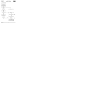 4
4 5
5 6
6 7
7 8
8 9
9 10
10 11
11 12
12 13
13 14
14 15
15 16
16 17
17 18
18 19
19 20
20 21
21 22
22 23
23 24
24 25
25 26
26 27
27 28
28 29
29 30
30 31
31 32
32 33
33 34
34 35
35 36
36 37
37 38
38 39
39 40
40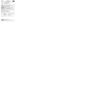 41
41 42
42 43
43 44
44 45
45 46
46 47
47 48
48 49
49 50
50 51
51 52
52 53
53 54
54 55
55 56
56 57
57 58
58 59
59 60
60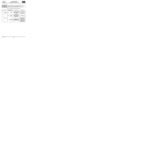 61
61 62
62 63
63 64
64 65
65 66
66 67
67 68
68 69
69 70
70 71
71 72
72 73
73 74
74 75
75 76
76 77
77 78
78 79
79 80
80 81
81 82
82 83
83 84
84 85
85 86
86 87
87 88
88 89
89 90
90 91
91 92
92 93
93 94
94 95
95 96
96 97
97 98
98 99
99 100
100 101
101 102
102 103
103 104
104 105
105 106
106