Page 97 of 107
17C-97
MR-372-J84-17C000$826.mif
V2
GAS INJECTION
Fault finding - Interpretation of commands
LPG 3000
Program No.
Vdiag No: 08/10
17C
AC024
LPG EXPANSION VALVE SOLENOID VALVE
NOTESWith ignition on and engine stopped.
Switch on the ignition and run command AC024.
If the LPG expansion valve solenoid valve does not click 10 times, follow the interpretation of fault DF103 LPG
expansion valve solenoid valve circuit.
AFTER REPAIRRepeat the conformity check from the start.
GAZ3000_V08_AC024 / GAZ3000_V10_AC024
Page 98 of 107
17C-98
MR-372-J84-17C000$885.mif
V2
17C
GAS INJECTION
Fault finding - Customer complaints
NOTESOnly check the customer complaint after performing a complete check with the fault
finding tool.
IMPORTANT
For any operation on a component of the LPG supply circuit, consult the safety
instructions (see 17D, LPG injection, Introduction).
NO DIALOGUE WITH THE COMPUTER ALP 1
LPG GAUGE FAULTSALP 2
THE ENGINE STALLS WHEN SWITCHED TO LPG MODE ALP 3
IDLE SPEED FAULTSALP 4
FAULTS WHILE DRIVINGALP 5
LPG LEAK
LPG LEAK WHEN REFILLING
THE TANKALP 6
LPG 3000
Program No.
Vdiag No: 08/10
MR-372-J84-17C000$885.mif
Page 99 of 107

ALP 1 No dialogue with the computer
NOTESNone.
Check for a + 12 V battery feed on track H4 and a + 12 V")
17C-99
MR-372-J84-17C000$944.mif
V2
17C
GAS INJECTION
Fault finding - Fault finding chart (ALP)
ALP 1 No dialogue with the computer
NOTESNone.
Check for a + 12 V battery feed on track H4 and a + 12 V after ignition feed (using the forced + after ignition
mode, see Introduction section) on track C2 of the LPG computer.
Repair if necessary.
Check the condition of the battery and the vehicle earths.
Repair if necessary.
Try the diagnostic tool on another vehicle.
–check the connection between the diagnostic tool and the diagnostic socket (lead in good condition),
–check fuse F5 (15 A) (for Mégane 2) and fuses F04 (10A) and F29 (15A) (for Logan).
Repair if necessary.
Check the insulation, continuity and the absence of interference resistance on the connections between:
LPG computer track H1
LPG computer track G1
LPG computer track B4Earth
Earth
track 7 of the diagnostic socket
Repair if necessary.
Use the diagnostic socket to check the following tracks:
Track 1
Track 16
Tracks 4 and 5+ After ignition
+ Battery
Earth
Repair if necessary.
AFTER REPAIRCheck using the diagnostic tool.
GAZ3000_V08_ALP1 / GAZ3000_V10_ALP1
LPG 3000
Program No: AB
Vdiag No: 08/10
MR-372-J84-17C000$944.mif
Page 100 of 107

LPG 3000
Program No: AB
Vdiag No: 08/10
17C
ALP 2 LPG sender fault
For Mégane II
IMPORTANT
When carrying")
17C-100
MR-372-J84-17C000$944.mif
V2
GAS INJECTION
Fault finding - Fault finding chart (ALP)
LPG 3000
Program No: AB
Vdiag No: 08/10
17C
ALP 2 LPG sender fault
For Mégane II
IMPORTANT
When carrying out an operation on an LPG supply circuit component, consult the safety instructions
(see 17D, Gas injection, Introduction, Safety instructions for all operations).
NOTESCheck that there is LPG in the tank.
Disconnect the LPG tank sender connector and check the voltage of the sensor signal using parameter
PR007 LPG tank sender signal voltage.
Replace the sensor if the signal voltage is not approximately:4.8 V tank full
1 V in reserve
0.2 V tank empty
Check for earth on track C (for Mégane 2) of the LPG tank connector.
Repair if necessary.
Check the insulation in relation to earth and the continuity and the absence of interference resistance on
the connection between:
For Mégane 2:
LPG computer track B1 track B of the LPG tank sender
If the fault is still present, check the intermediate connectors (R2 track 36 and R34 track 34 for Mégane 2).
Repair if necessary.
If the fault is still present, check the LPG tank pressure sensor (see MR 364 Mechanical, 17D, LPG injection).
AFTER REPAIRCheck using the diagnostic tool.
GAZ3000_V08_ALP2 / GAZ3000_V10_ALP2
Page 101 of 107

LPG 3000
Program No: AB
Vdiag No: 08/10
17C
ALP 2
CONTINUED 1
For Logan
IMPORTANT
When carrying out an op")
17C-101
MR-372-J84-17C000$944.mif
V2
GAS INJECTION
Fault finding - Fault finding chart (ALP)
LPG 3000
Program No: AB
Vdiag No: 08/10
17C
ALP 2
CONTINUED 1
For Logan
IMPORTANT
When carrying out an operation on an LPG supply circuit component, consult the safety instructions
(see 17D, Gas injection, Introduction, Safety instructions for all operations).
NOTESAsk the customer if the problem always arises.
If it is not the case, do not replace the sensor, as it is not the cause.
Is the fault that the tank is not displaying full when it has just been filled with LPG?
Check that the tank has just been filled with LPG, otherwise refill it.
If the customer complaint is reproduced, continue fault finding.
If not, the fault does not always arise. Do not replace the sensor and deal
with the next customer complaint.
Disconnect the connector from the LPG tank sender and measure
the resistance between tracks A1 and A.
Replace the LPG tank sender if the resistance value is less than 5 kOhms,
because the sensor is incorrect.
If the fault is still present, contact the Techline.
Is the fault related to the LPG warning not being displayed when the tank is empty?
NOYES
YES
A
AFTER REPAIRCheck using the diagnostic tool.
Page 102 of 107
17C-102
MR-372-J84-17C000$944.mif
V2
GAS INJECTION
Fault finding - Fault finding chart (ALP)
LPG 3000
Program No: AB
Vdiag No: 08/10
17C
ALP 2
CONTINUED 2
Check that the tank is empty, otherwise empty it by going for a drive.
If the customer complaint is reproduced, continue fault finding.
If not, the fault does not always arise. Do not replace the sensor and deal with the next customer complaint.
Disconnect the connector from the LPG tank sender and measure the resistance between tracks A1 and A.
Replace the LPG tank sender if the resistance value is greater than 2.1 kOhms, because the sensor is incorrect.
If the fault is still present, contact the Techline.
A
YES
AFTER REPAIRCheck using the diagnostic tool.
Page 103 of 107

LPG 3000
Program No: AB
Vdiag No: 08/10
17C
ALP 3 The engine stalls when switched to LPG mode
IMPORTANT
W")
17C-103
MR-372-J84-17C000$944.mif
V2
GAS INJECTION
Fault finding - Fault finding chart (ALP)
LPG 3000
Program No: AB
Vdiag No: 08/10
17C
ALP 3 The engine stalls when switched to LPG mode
IMPORTANT
When carrying out an operation on an LPG supply circuit component, consult the safety instructions
(see 17D, Gas injection, Introduction, Safety instructions for all operations).
NOTESCheck that there is LPG in the tank.
Check the condition of the air filter.
Replace the filter if necessary.
Check that the LPG supply pipes are not pinched or crushed.
Replace the faulty pipes if necessary.
Check the expansion valve cooling circuit (see MR 364 Mechanics, 17D, LPG injection, Expansion valve).
Repair the circuit if necessary.
Measure the resistance between tracks 1 and 2 of the injectors.
Replace the injectors if their resistance value at approximately 20°C is not between:
0.77 Ω < R < 1.43 Ω
Check the following connections for insulation from earth, continuity and absence of extraneous
resistance:
Main relay track 5
Main relay track 5
Main relay track 5
Main relay track 5track 1of injector 1
track 1of injector 2
track 1of injector 3
track 1of injector 4
Check the insulation from + 12 V, the continuity and the absence of interference resistance of
the connections between:
LPG computer track G3
LPG computer track G4
LPG computer track H2
LPG Computer track H3track 2 of injector 1
track 2 of injector 2
track 2 of injector 3
track 2 of injector 4
If necessary, repair the defective connections.
AFTER REPAIRCheck using the diagnostic tool.
GAZ3000_V08_ALP3 / GAZ3000_V10_ALP3
Page 104 of 107
17C-104
MR-372-J84-17C000$944.mif
V2
GAS INJECTION
Fault finding - Fault finding chart (ALP)
LPG 3000
Program No: AB
Vdiag No: 08/10
17C
ALP 3
CONTINUED
Test the operation of the injectors.
Run commands AC018 Cylinder 4 injector, AC019 Cylinder 3 injector, AC020 Cylinder 2 injector
and AC021 Cylinder 1 injector.
Run the engine in petrol mode.
Disconnect the LPG tank connector and switch to LPG mode.
Check for + 12 Von track 1 of the LPG tank relay connector.
Repair if necessary.
Check for earth on track 2 of the LPG tank relay connector.
Repair if necessary.
Measure the resistance between tracks A4 and A5 (for Mégane 2) or tracks 1 and 2 (for Logan) of the LPG
tank solenoid valve.
Replace the solenoid valve if the resistance value is not approximately 12.6 Ω.
AFTER REPAIRCheck using the diagnostic tool.
 1
1 2
2 3
3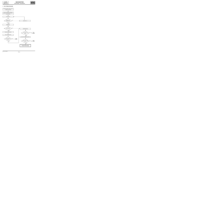 4
4 5
5 6
6 7
7 8
8 9
9 10
10 11
11 12
12 13
13 14
14 15
15 16
16 17
17 18
18 19
19 20
20 21
21 22
22 23
23 24
24 25
25 26
26 27
27 28
28 29
29 30
30 31
31 32
32 33
33 34
34 35
35 36
36 37
37 38
38 39
39 40
40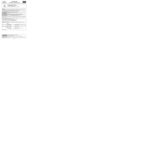 41
41 42
42 43
43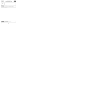 44
44 45
45 46
46 47
47 48
48 49
49 50
50 51
51 52
52 53
53 54
54 55
55 56
56 57
57 58
58 59
59 60
60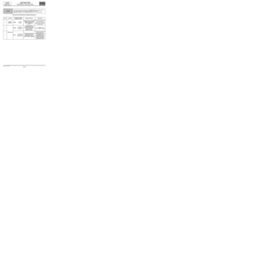 61
61 62
62 63
63 64
64 65
65 66
66 67
67 68
68 69
69 70
70 71
71 72
72 73
73 74
74 75
75 76
76 77
77 78
78 79
79 80
80 81
81 82
82 83
83 84
84 85
85 86
86 87
87 88
88 89
89 90
90 91
91 92
92 93
93 94
94 95
95 96
96 97
97 98
98 99
99 100
100 101
101 102
102 103
103 104
104 105
105 106
106


LPG 3000
Program No: AB
Vdiag No: 08/10
17C
ALP 2
CONTINUED 2
Check that the tank is empty, otherwise emp")

LPG 3000
Program No: AB
Vdiag No: 08/10
17C
ALP 3
CONTINUED
Test the operation of the injectors.
Run comm")