2008 NISSAN TIIDA check engine
[x] Cancel search: check enginePage 1732 of 2771
CAMSHAFT
EM-55
< SERVICE INFORMATION >
C
D
E
F
G
H
I
J
K
L
MA
EM
N
P O
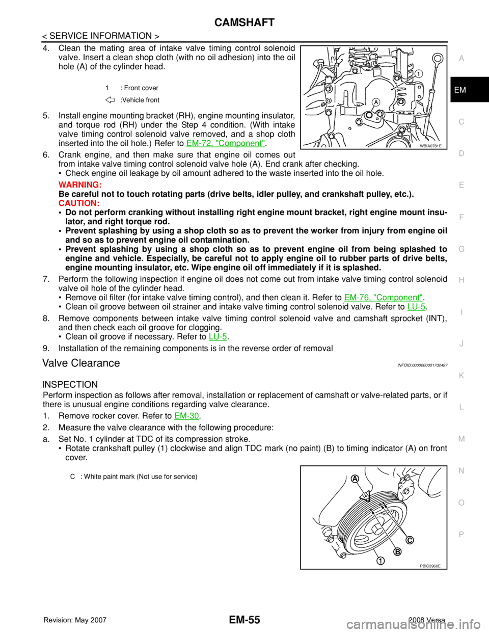
4. Clean the mating area of intake valve timing control solenoid
valve. Insert a clean shop cloth (with no oil adhesion) into the oil
hole (A) of the cylinder head.
5. Install engine mounting bracket (RH), engine mounting insulator,
and torque rod (RH) under the Step 4 condition. (With intake
valve timing control solenoid valve removed, and a shop cloth
inserted into the oil hole.) Refer to EM-72, "
Component".
6. Crank engine, and then make sure that engine oil comes out
from intake valve timing control solenoid valve hole (A). End crank after checking.
• Check engine oil leakage by oil amount adhered to the waste inserted into the oil hole.
WARNING:
Be careful not to touch rotating parts (drive belts, idler pulley, and crankshaft pulley, etc.).
CAUTION:
• Do not perform cranking without installing right engine mount bracket, right engine mount insu-
lator, and right torque rod.
• Prevent splashing by using a shop cloth so as to prevent the worker from injury from engine oil
and so as to prevent engine oil contamination.
• Prevent splashing by using a shop cloth so as to prevent engine oil from being splashed to
engine and vehicle. Especially, be careful not to apply engine oil to rubber parts of drive belts,
engine mounting insulator, etc. Wipe engine oil off immediately if it is splashed.
7. Perform the following inspection if engine oil does not come out from intake valve timing control solenoid
valve oil hole of the cylinder head.
• Remove oil filter (for intake valve timing control), and then clean it. Refer to EM-76, "
Component".
• Clean oil groove between oil strainer and intake valve timing control solenoid valve. Refer to LU-5
.
8. Remove components between intake valve timing control solenoid valve and camshaft sprocket (INT),
and then check each oil groove for clogging.
• Clean oil groove if necessary. Refer to LU-5
.
9. Installation of the remaining components is in the reverse order of removal
Valve ClearanceINFOID:0000000001702497
INSPECTION
Perform inspection as follows after removal, installation or replacement of camshaft or valve-related parts, or if
there is unusual engine conditions regarding valve clearance.
1. Remove rocker cover. Refer to EM-30
.
2. Measure the valve clearance with the following procedure:
a. Set No. 1 cylinder at TDC of its compression stroke.
• Rotate crankshaft pulley (1) clockwise and align TDC mark (no paint) (B) to timing indicator (A) on front
cover.
1 : Front cover
:Vehicle front
WBIA0781E
C : White paint mark (Not use for service)
PBIC3960E
Page 1739 of 2771
EM-62
< SERVICE INFORMATION >
CYLINDER HEAD
CYLINDER HEAD
On-Vehicle ServiceINFOID:0000000001702501
CHECKING COMPRESSION PRESSURE
1. Warm up engine thoroughly. Then, stop it.
2. Release fuel pressure. Refer to EC-78, "
Fuel Pressure Check".
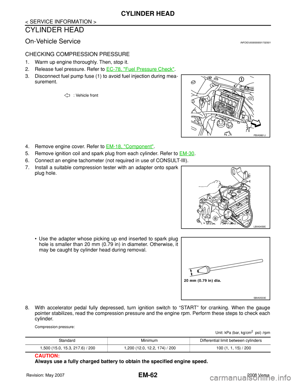
3. Disconnect fuel pump fuse (1) to avoid fuel injection during mea-
surement.
4. Remove engine cover. Refer to EM-18, "
Component".
5. Remove ignition coil and spark plug from each cylinder. Refer to EM-30
.
6. Connect an engine tachometer (not required in use of CONSULT-III).
7. Install a suitable compression tester with an adapter onto spark
plug hole.
• Use the adapter whose picking up end inserted to spark plug
hole is smaller than 20 mm (0.79 in) in diameter. Otherwise, it
may be caught by cylinder head during removal.
8. With accelerator pedal fully depressed, turn ignition switch to “START” for cranking. When the gauge
pointer stabilizes, read the compression pressure and the engine rpm. Perform these steps to check each
cylinder.
Compression pressure:
Unit: kPa (bar, kg/cm2 psi) /rpm
CAUTION:
Always use a fully charged battery to obtain the specified engine speed.
: Vehicle front
PBIA9861J
LBIA0459E
SBIA0533E
Standard Minimum Differential limit between cylinders
1,500 (15.0, 15.3, 217.6) / 200 1,200 (12.0, 12.2, 174) / 200 100 (1, 1, 15) / 200
Page 1740 of 2771
CYLINDER HEAD
EM-63
< SERVICE INFORMATION >
C
D
E
F
G
H
I
J
K
L
MA
EM
N
P O
• If the engine speed is out of the specified range, check battery liquid for proper gravity. Check engine
speed again with normal battery gravity.
• If compression pressure is below minimum value, check valve clearances and parts associated with
combustion chamber (Valve, valve seat, piston, piston ring, cylinder bore, cylinder head, cylinder head
gasket). After the checking, measure the compression pressure again.
• If some cylinder has low compression pressure, pour small amount of engine oil into the spark plug hole
of the cylinder to re-check it for compression.
- If the added engine oil improves the compression, piston rings may be worn out or damaged. Check pis-
ton rings and replace if necessary.
- If the compression pressure remains at low level despite the addition of engine oil, valves may be mal-
functioning. Check valves for damage. Replace valve or valve seat accordingly.
• If two adjacent cylinders have respectively low compression pressure and their compression remains
low even after the addition of engine oil, cylinder head gasket is leaking. In such a case, replace cylinder
head gasket.
9. After inspection is completed, install removed parts.
10. Start the engine, and confirm that the engine runs smoothly.
11. Perform trouble diagnosis. If DTC appears, erase it. Refer to EC-81
.
ComponentINFOID:0000000001702502
Removal and InstallationINFOID:0000000001702503
REMOVAL
WARNING:
• Put a “CAUTION: FLAMMABLE” sign in the workshop.
• Be sure to work in a well ventilated area and furnish workshop with a CO
2 fire extinguisher.
• Do not smoke while servicing fuel system. Keep open flames and sparks away from the work area.
1. Release the fuel pressure. Refer to EC-78, "
Fuel Pressure Check".
2. Drain engine coolant and engine oil. Refer to CO-8
and LU-6.
3. Remove front fender protector (RH). Refer to EI-23
.
4. Remove drive belt. Refer to EM-13, "
Removal and Installation".
5. Remove the following components and related parts.
• Exhaust manifold; Refer to EM-21
.
• Intake manifold; Refer to EM-18
.
• Fuel tube and fuel injector assembly; Refer to EM-33
.
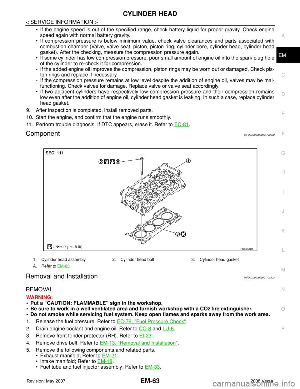
1. Cylinder head assembly 2. Cylinder head bolt 3. Cylinder head gasket
A. Refer to EM-63
PBIC3542J
Page 1741 of 2771
EM-64
< SERVICE INFORMATION >
CYLINDER HEAD
• Water outlet; Refer to CO-19.
• Rocker cover; Refer to EM-30
.
• Front cover, timing chain; Refer to EM-37
.
• Camshaft; Refer to EM-47
.
6. Remove cylinder head.
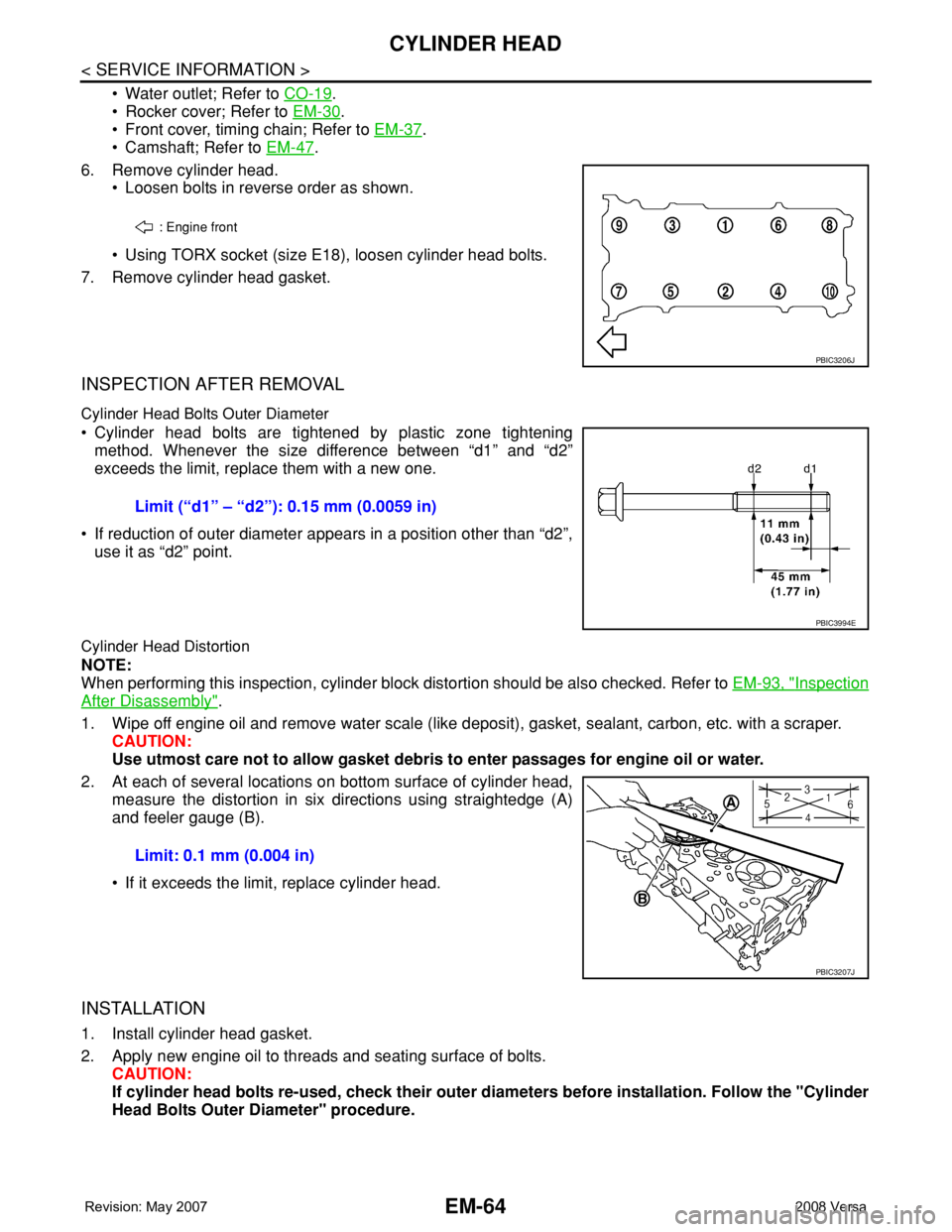
• Loosen bolts in reverse order as shown.
• Using TORX socket (size E18), loosen cylinder head bolts.
7. Remove cylinder head gasket.
INSPECTION AFTER REMOVAL
Cylinder Head Bolts Outer Diameter
• Cylinder head bolts are tightened by plastic zone tightening
method. Whenever the size difference between “d1” and “d2”
exceeds the limit, replace them with a new one.
• If reduction of outer diameter appears in a position other than “d2”,
use it as “d2” point.
Cylinder Head Distortion
NOTE:
When performing this inspection, cylinder block distortion should be also checked. Refer to EM-93, "
Inspection
After Disassembly".
1. Wipe off engine oil and remove water scale (like deposit), gasket, sealant, carbon, etc. with a scraper.
CAUTION:
Use utmost care not to allow gasket debris to enter passages for engine oil or water.
2. At each of several locations on bottom surface of cylinder head,
measure the distortion in six directions using straightedge (A)
and feeler gauge (B).
• If it exceeds the limit, replace cylinder head.
INSTALLATION
1. Install cylinder head gasket.
2. Apply new engine oil to threads and seating surface of bolts.
CAUTION:
If cylinder head bolts re-used, check their outer diameters before installation. Follow the "Cylinder
Head Bolts Outer Diameter" procedure.
: Engine front
PBIC3206J
Limit (“d1” – “d2”): 0.15 mm (0.0059 in)
PBIC3994E
Limit: 0.1 mm (0.004 in)
PBIC3207J
Page 1742 of 2771
CYLINDER HEAD
EM-65
< SERVICE INFORMATION >
C
D
E
F
G
H
I
J
K
L
MA
EM
N
P O
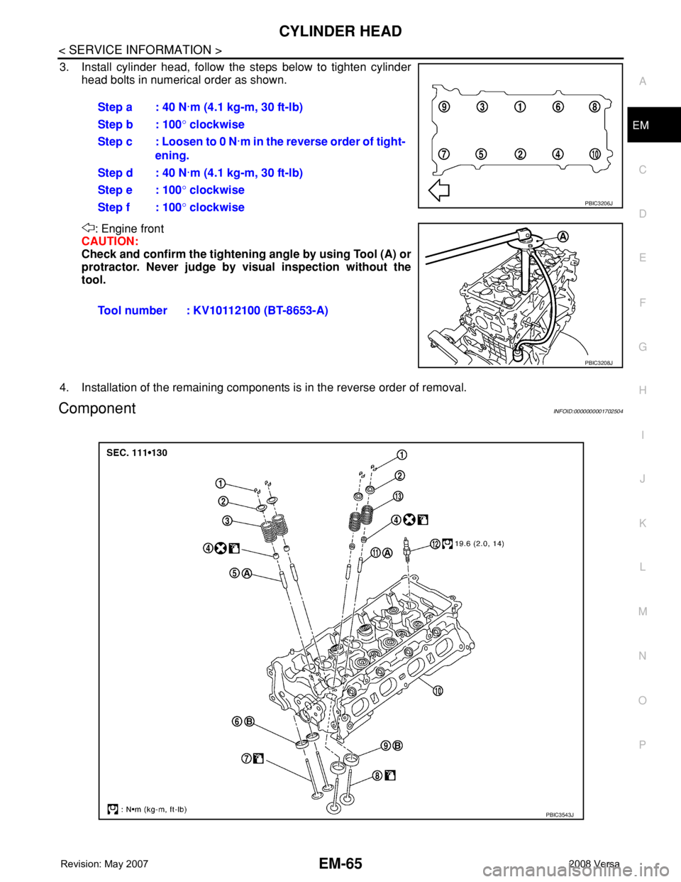
3. Install cylinder head, follow the steps below to tighten cylinder
head bolts in numerical order as shown.
: Engine front
CAUTION:
Check and confirm the tightening angle by using Tool (A) or
protractor. Never judge by visual inspection without the
tool.
4. Installation of the remaining components is in the reverse order of removal.
ComponentINFOID:0000000001702504
Step a : 40 N·m (4.1 kg-m, 30 ft-lb)
Step b : 100° clockwise
Step c : Loosen to 0 N·m in the reverse order of tight-
ening.
Step d : 40 N·m (4.1 kg-m, 30 ft-lb)
Step e : 100° clockwise
Step f : 100° clockwise
Tool number : KV10112100 (BT-8653-A)
PBIC3206J
PBIC3208J
PBIC3543J
Page 1750 of 2771
ENGINE ASSEMBLY
EM-73
< SERVICE INFORMATION >
C
D
E
F
G
H
I
J
K
L
MA
EM
N
P O
• Use either 2-pole lift type or separate type lift as best you can. If board-on type is used for unavoid-
able reasons, support at the rear axle jacking point with a transmission jack or similar tool before
starting work, in preparation for the backward shift of center of gravity.
• For supporting points for lifting and jacking point at rear axle, refer to GI-38, "
Garage Jack and
Safety Stand and 2-Pole Lift".
REMOVAL
Remove the engine and the transaxle assembly from the vehicle downward. Separate the engine and the tran-
saxle.
1. Remove engine undercover
2. Drain engine coolant from radiator. Refer to CO-8, "
Changing Engine Coolant".
CAUTION:
• Perform this step when the engine is cold.
• Do not spill engine coolant on drive belt.
3. Remove front fender protector (RH and LH); Refer to EI-23
.
4. Remove exhaust front tube; Refer to EX-4
.
5. Remove drive shafts (LH and RH) from steering knuckle. Refer to FAX-8
.
6. Remove transaxle joint bolts which pierce at oil pan (upper) lower rear side. Refer to AT-226
(A/T models),
CVT-178
(CVT) or MT-16 (M/T models).
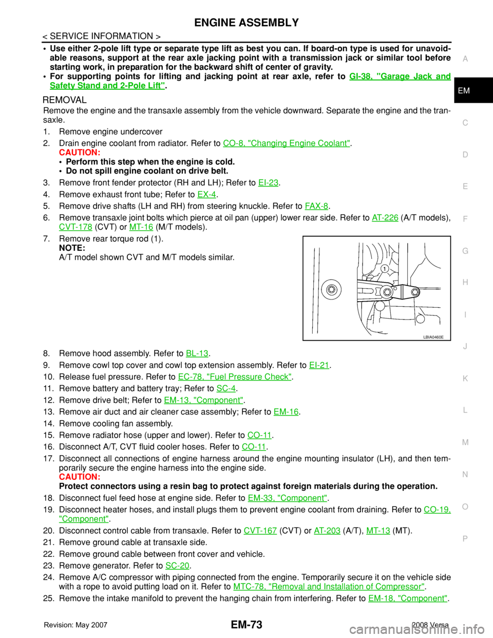
7. Remove rear torque rod (1).
NOTE:
A/T model shown CVT and M/T models similar.
8. Remove hood assembly. Refer to BL-13
.
9. Remove cowl top cover and cowl top extension assembly. Refer to EI-21
.
10. Release fuel pressure. Refer to EC-78, "
Fuel Pressure Check".
11. Remove battery and battery tray; Refer to SC-4
.
12. Remove drive belt; Refer to EM-13, "
Component".
13. Remove air duct and air cleaner case assembly; Refer to EM-16
.
14. Remove cooling fan assembly.
15. Remove radiator hose (upper and lower). Refer to CO-11
.
16. Disconnect A/T, CVT fluid cooler hoses. Refer to CO-11
.
17. Disconnect all connections of engine harness around the engine mounting insulator (LH), and then tem-
porarily secure the engine harness into the engine side.
CAUTION:
Protect connectors using a resin bag to protect against foreign materials during the operation.
18. Disconnect fuel feed hose at engine side. Refer to EM-33, "
Component".
19. Disconnect heater hoses, and install plugs them to prevent engine coolant from draining. Refer to CO-19,
"Component".
20. Disconnect control cable from transaxle. Refer to CVT-167
(CVT) or AT-203 (A/T), MT-13 (MT).
21. Remove ground cable at transaxle side.
22. Remove ground cable between front cover and vehicle.
23. Remove generator. Refer to SC-20
.
24. Remove A/C compressor with piping connected from the engine. Temporarily secure it on the vehicle side
with a rope to avoid putting load on it. Refer to MTC-78, "
Removal and Installation of Compressor".
25. Remove the intake manifold to prevent the hanging chain from interfering. Refer to EM-18, "
Component".
LBIA0460E
Page 1751 of 2771
EM-74
< SERVICE INFORMATION >
ENGINE ASSEMBLY
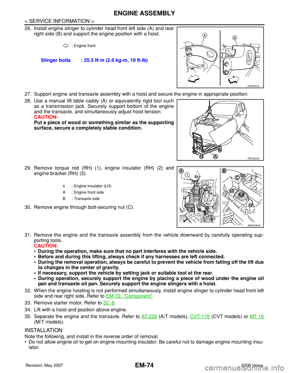
26. Install engine slinger to cylinder head front left side (A) and rear
right side (B) and support the engine position with a hoist.
27. Support engine and transaxle assembly with a hoist and secure the engine in appropriate position.
28. Use a manual lift table caddy (A) or equivalently rigid tool such
as a transmission jack. Securely support bottom of the engine
and the transaxle, and simultaneously adjust hoist tension.
CAUTION:
Put a piece of wood or something similar as the supporting
surface, secure a completely stable condition.
29. Remove torque rod (RH) (1), engine insulator (RH) (2) and
engine bracket (RH) (3).
30. Remove engine through bolt-securing nut (C).
31. Remove the engine and the transaxle assembly from the vehicle downward by carefully operating sup-
porting tools.
CAUTION:
• During the operation, make sure that no part interferes with the vehicle side.
• Before and during this lifting, always check if any harnesses are left connected.
• During the removal operation, always be careful to prevent the vehicle from falling off the lift due
to changes in the center of gravity.
• If necessary, support the vehicle by setting jack or suitable tool at the rear.
• During operation, securely support the engine by placing a piece of wood under the engine oil
pan and transaxle oil pan. Securely support the engine slingers with a hoist.
32. When the engine hoisting is not performed simultaneously, install engine slinger to cylinder head front left
side and rear right side. Refer to EM-72, "
Component".
33. Remove starter motor. Refer to SC-8
.
34. Lift with a hoist and position above engine.
35. Separate the engine and the transaxle. Refer to AT-226
(A/T models), CVT-178 (CVT models) or MT-16
(M/T models).
INSTALLATION
Note the following, and install in the reverse order of removal.
• Do not allow engine oil to get on engine mounting insulator. Be careful not to damage engine mounting insu-
lator.
: Engine front
Slinger bolts : 25.5 N·m (2.6 kg-m, 19 ft-lb)
LBIA0461E
PBIC3223J
4 : Engine insulator (LH)
A : Engine front side
B : Transaxle side
WBIA0784E
Page 1752 of 2771
ENGINE ASSEMBLY
EM-75
< SERVICE INFORMATION >
C
D
E
F
G
H
I
J
K
L
MA
EM
N
P O
• When installation directions are specified, install parts according to the directions. Refer to EM-72, "Compo-
nent".
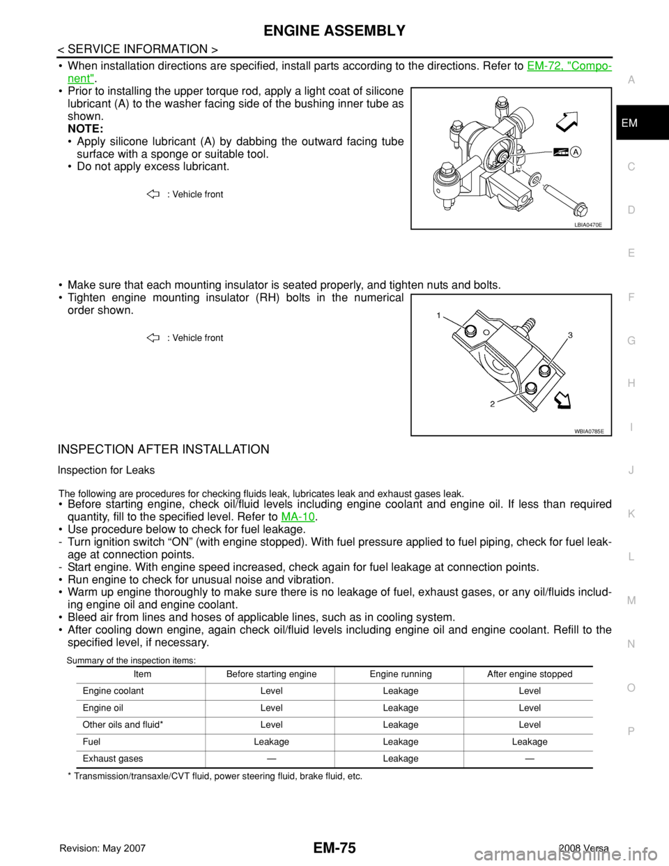
• Prior to installing the upper torque rod, apply a light coat of silicone
lubricant (A) to the washer facing side of the bushing inner tube as
shown.
NOTE:
• Apply silicone lubricant (A) by dabbing the outward facing tube
surface with a sponge or suitable tool.
• Do not apply excess lubricant.
• Make sure that each mounting insulator is seated properly, and tighten nuts and bolts.
• Tighten engine mounting insulator (RH) bolts in the numerical
order shown.
INSPECTION AFTER INSTALLATION
Inspection for Leaks
The following are procedures for checking fluids leak, lubricates leak and exhaust gases leak.
• Before starting engine, check oil/fluid levels including engine coolant and engine oil. If less than required
quantity, fill to the specified level. Refer to MA-10
.
• Use procedure below to check for fuel leakage.
- Turn ignition switch “ON” (with engine stopped). With fuel pressure applied to fuel piping, check for fuel leak-
age at connection points.
- Start engine. With engine speed increased, check again for fuel leakage at connection points.
• Run engine to check for unusual noise and vibration.
• Warm up engine thoroughly to make sure there is no leakage of fuel, exhaust gases, or any oil/fluids includ-
ing engine oil and engine coolant.
• Bleed air from lines and hoses of applicable lines, such as in cooling system.
• After cooling down engine, again check oil/fluid levels including engine oil and engine coolant. Refill to the
specified level, if necessary.
Summary of the inspection items:
* Transmission/transaxle/CVT fluid, power steering fluid, brake fluid, etc.: Vehicle front
LBIA0470E
: Vehicle front
WBIA0785E
Item Before starting engine Engine running After engine stopped
Engine coolant Level Leakage Level
Engine oil Level Leakage Level
Other oils and fluid* Level Leakage Level
Fuel Leakage Leakage Leakage
Exhaust gases — Leakage —