2008 NISSAN TIIDA check engine
[x] Cancel search: check enginePage 1617 of 2771
REFRIGERANT PRESSURE SENSOR
EC-543
< SERVICE INFORMATION >
C
D
E
F
G
H
I
J
K
L
MA
EC
N
P O
Diagnosis ProcedureINFOID:0000000001703078
1.CHECK REFRIGERANT PRESSURE SENSOR OVERALL FUNCTION
1. Start engine and warm it up to normal operating temperature.
2. Turn A/C switch and blower fan switch ON.
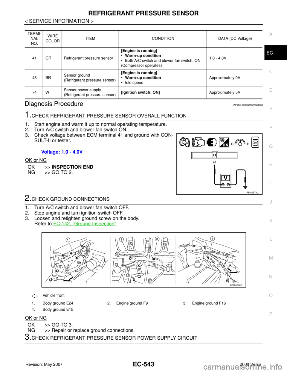
3. Check voltage between ECM terminal 41 and ground with CON-
SULT-II or tester.
OK or NG
OK >>INSPECTION END
NG >> GO TO 2.
2.CHECK GROUND CONNECTIONS
1. Turn A/C switch and blower fan switch OFF.
2. Stop engine and turn ignition switch OFF.
3. Loosen and retighten ground screw on the body.
Refer to EC-142, "
Ground Inspection".
OK or NG
OK >> GO TO 3.
NG >> Repair or replace ground connections.
3.CHECK REFRIGERANT PRESSURE SENSOR POWER SUPPLY CIRCUIT
TERMI-
NAL
NO.WIRE
COLORITEM CONDITION DATA (DC Voltage)
41 GR Refrigerant pressure sensor[Engine is running]
•Warm-up condition
• Both A/C switch and blower fan switch: ON
(Compressor operates)1.0 - 4.0V
48 BRSensor ground
(Refrigerant pressure sensor)[Engine is running]
•Warm-up condition
• Idle speedApproximately 0V
74 WSensor power supply
(Refrigerant pressure sensor)[Ignition switch: ON]Approximately 5V
Voltage: 1.0 - 4.0V
PBIA9574J
:Vehicle front
1. Body ground E24 2. Engine ground F9 3. Engine ground F16
4. Body ground E15
BBIA0698E
Page 1629 of 2771
EI-6
< SYMPTOM DIAGNOSIS >
SQUEAK AND RATTLE TROUBLE DIAGNOSIS
If possible, drive the vehicle with the customer until the noise is duplicated. Note any additional information on
the Diagnostic Worksheet regarding the conditions or location of the noise. This information can be used to
duplicate the same conditions when you confirm the repair.
If the noise can be duplicated easily during the test drive, to help identify the source of the noise, try to dupli-
cate the noise with the vehicle stopped by doing one or all of the following:
• Close a door.
• Tap or push/pull around the area where the noise appears to be coming from.
• Rev the engine.
• Use a floor jack to recreate vehicle “twist”.
• At idle, apply engine load (electrical load, half-clutch on M/T model, drive position on A/T model).
• Raise the vehicle on a hoist and hit a tire with a rubber hammer.
• Drive the vehicle and attempt to duplicate the conditions the customer states exist when the noise occurs.
• If it is difficult to duplicate the noise, drive the vehicle slowly on an undulating or rough road to stress the
vehicle body.
CHECK RELATED SERVICE BULLETINS
After verifying the customer concern or symptom, check ASIST for Technical Service Bulletins (TSBs) related
to that concern or symptom.
If a TSB relates to the symptom, follow the procedure to repair the noise.
LOCATE THE NOISE AND IDENTIFY THE ROOT CAUSE
1. Narrow down the noise to a general area. To help pinpoint the source of the noise, use a listening tool
(Chassis Ear: J-39570, Engine Ear: J-39565 and mechanics stethoscope).
2. Narrow down the noise to a more specific area and identify the cause of the noise by:
• Removing the components in the area that you suspect the noise is coming from.
Do not use too much force when removing clips and fasteners, otherwise clips and fasteners
can be broken or lost during the repair, resulting in the creation of new noise.
• Tapping or pushing/pulling the component that you suspect is causing the noise.
Do not tap or push/pull the component with excessive force, otherwise the noise will be elimi-
nated only temporarily.
• Feeling for a vibration with your hand by touching the component(s) that you suspect is (are) causing
the noise.
• Placing a piece of paper between components that you suspect are causing the noise.
• Looking for loose components and contact marks.
Refer to EI-7, "
Generic Squeak and Rattle Troubleshooting".
REPAIR THE CAUSE
• If the cause is a loose component, tighten the component securely.
• If the cause is insufficient clearance between components:
- Separate components by repositioning or loosening and retightening the component, if possible.
- Insulate components with a suitable insulator such as urethane pads, foam blocks, felt cloth tape or ure-
thane tape. A NISSAN Squeak and Rattle Kit (J-43980) is available through your authorized NISSAN Parts
Department.
CAUTION:
Do not use excessive force as many components are constructed of plastic and may be damaged.
Always check with the Parts Department for the latest parts information.
The following materials are contained in the NISSAN Squeak and Rattle Kit (J-43980). Each item can be
ordered separately as needed.
URETHANE PADS [1.5 mm (0.059 in) thick]
Insulates connectors, harness, etc.
76268-9E005: 100 x 135 mm (3.94 x 5.31 in)/76884-71L01: 60 x 85 mm (2.36 x 3.35 in)/76884-71L02: 15 x 25
mm (0.59 x 0.98 in)
INSULATOR (Foam blocks)
Insulates components from contact. Can be used to fill space behind a panel.
73982-9E000: 45 mm (1.77 in) thick, 50 x 50 mm (1.97 x 1.97 in)/73982-50Y00: 10 mm (0.39 in) thick, 50 x 50
mm (1.97 x 1.97 in)
INSULATOR (Light foam block)
80845-71L00: 30 mm (1.18 in) thick, 30 x 50 mm (1.18 x 1.97 in)
FELT CLOTH TAPE
Used to insulate where movement does not occur. Ideal for instrument panel applications.
68370-4B000: 15 x 25 mm (0.59 x 0.98 in) pad/68239-13E00: 5 mm (0.20 in) wide tape roll
Page 1678 of 2771
EM-1
ENGINE
C
D
E
F
G
H
I
J
K
L
M
SECTION EM
A
EM
N
O
P
CONTENTS
ENGINE MECHANICAL
SERVICE INFORMATION ............................3
PRECAUTIONS ...................................................3
Precaution for Supplemental Restraint System
(SRS) "AIR BAG" and "SEAT BELT PRE-TEN-
SIONER" ...................................................................
3
Precaution for Procedure without Cowl Top Cover ......3
Precaution Necessary for Steering Wheel Rota-
tion After Battery Disconnect .....................................
3
Precaution for Drain Coolant .....................................4
Precaution for Disconnecting Fuel Piping .................4
Precaution for Removal and Disassembly ................4
Precaution for Inspection, Repair and Replace-
ment ..........................................................................
4
Precaution for Assembly and Installation ..................4
Parts Requiring Angular Tightening ..........................4
Precaution for Liquid Gasket .....................................5
PREPARATION ...................................................7
Special Service Tool .................................................7
Commercial Service Tool ..........................................9
NOISE, VIBRATION AND HARSHNESS
(NVH) TROUBLESHOOTING ............................
11
NVH Troubleshooting - Engine Noise .....................11
Use the Chart Below to Help You Find the Cause
of the Symptom .......................................................
12
DRIVE BELTS ....................................................13
Component ..............................................................13
Checking Drive Belts ...............................................13
Tension Adjustment ................................................13
Removal and Installation .........................................13
Component ..............................................................14
Removal and Installation of Drive Belt Auto Ten-
sioner ......................................................................
14
AIR CLEANER AND AIR DUCT ........................16
Component ..............................................................16
Removal and Installation .........................................16
Changing Air Cleaner Filter .....................................17
INTAKE MANIFOLD .........................................18
Component ..............................................................18
Removal and Installation .........................................18
EXHAUST MANIFOLD ......................................21
Component ..............................................................21
Removal and Installation .........................................21
OIL PAN ............................................................24
Component ..............................................................24
Removal and Installation .........................................24
IGNITION COIL, SPARK PLUG AND ROCK-
ER COVER ........................................................
30
Component ..............................................................30
Removal and Installation .........................................30
FUEL INJECTOR AND FUEL TUBE ................33
Component ..............................................................33
Removal and Installation .........................................33
TIMING CHAIN ..................................................37
Component ..............................................................37
Removal and Installation .........................................38
CAMSHAFT .......................................................47
Component ..............................................................47
Removal and Installation .........................................47
Valve Clearance ......................................................55
OIL SEAL ..........................................................59
Removal and Installation of Valve Oil Seal ..............59
Removal and Installation of Front Oil Seal ..............59
Removal and Installation of Rear Oil Seal ...............60
CYLINDER HEAD .............................................62
On-Vehicle Service ..................................................62
Component ..............................................................63
Removal and Installation .........................................63
Component ..............................................................65
Disassembly and Assembly .....................................66
Inspection After Disassembly ..................................67
Page 1681 of 2771

EM-4
< SERVICE INFORMATION >
PRECAUTIONS
2. Use the Intelligent Key or mechanical key to turn the ignition switch to the ″ACC″ position. At this time, the
steering lock will be released.
3. Disconnect both battery cables. The steering lock will remain released and the steering wheel can be
rotated.
4. Perform the necessary repair operation.
5. When the repair work is completed, return the ignition switch to the ″LOCK″ position before connecting
the battery cables. (At this time, the steering lock mechanism will engage.)
6. Perform a self-diagnosis check of all control units using CONSULT-III.
Precaution for Drain CoolantINFOID:0000000001702463
• Drain coolant when engine is cooled.
Precaution for Disconnecting Fuel PipingINFOID:0000000001702464
• Before starting work, make sure no fire or spark producing items are in the work area.
• Release fuel pressure before disassembly.
• After disconnecting pipes, plug openings to stop fuel leakage.
Precaution for Removal and DisassemblyINFOID:0000000001702465
• When instructed to use special service tools, use the specified tools. Always be careful to work safely, avoid
forceful or uninstructed operations.
• Exercise maximum care to avoid damage to mating or sliding surfaces.
• Cover openings of engine system with tape or the equivalent, if necessary, to seal out foreign materials.
• Mark and arrange disassembly parts in an organized way for easy troubleshooting and assembly.
• When loosening nuts and bolts, as a basic rule, start with the one furthest outside, then the one diagonally
opposite, and so on. If the order of loosening is specified, do exactly as specified. Power tools may be used
where noted in the step.
Precaution for Inspection, Repair and ReplacementINFOID:0000000001702466
• Before repairing or replacing, thoroughly inspect parts. Inspect new replacement parts in the same way, and
replace if necessary.
Precaution for Assembly and InstallationINFOID:0000000001702467
• Use torque wrench to tighten bolts or nuts to specification.
• When tightening nuts and bolts, as a basic rule, equally tighten in several different steps starting with the
ones in center, then ones on inside and outside diagonally in this order. If the order of tightening is specified,
do exactly as specified.
• Replace with new gasket, packing, oil seal or O-ring.
• Thoroughly wash, clean, and air-blow each part. Carefully check oil or coolant passages for any restriction
and blockage.
• Avoid damaging sliding or mating surfaces. Completely remove foreign materials such as cloth lint or dust.
Before assembly, oil sliding surfaces well.
• Release air within route after draining coolant.
• Before starting engine, apply fuel pressure to fuel lines with turning ignition switch ON (with engine stopped).
Then make sure that there are no leaks at fuel line connections.
• After repairing, start engine and increase engine speed to check coolant, fuel, oil, and exhaust systems for
leakage.
Parts Requiring Angular TighteningINFOID:0000000001702468
• Use an angle wrench for the final tightening of the following engine parts:
- Cylinder head bolts
- Camshaft sprocket (INT)
- Main bearing cap bolts
- Connecting rod cap nuts
- Crankshaft pulley bolt (No angle wrench is required as the bolt flange is provided with notches for angular
tightening)
Page 1689 of 2771
EM-12
< SERVICE INFORMATION >
NOISE, VIBRATION AND HARSHNESS (NVH) TROUBLESHOOTING
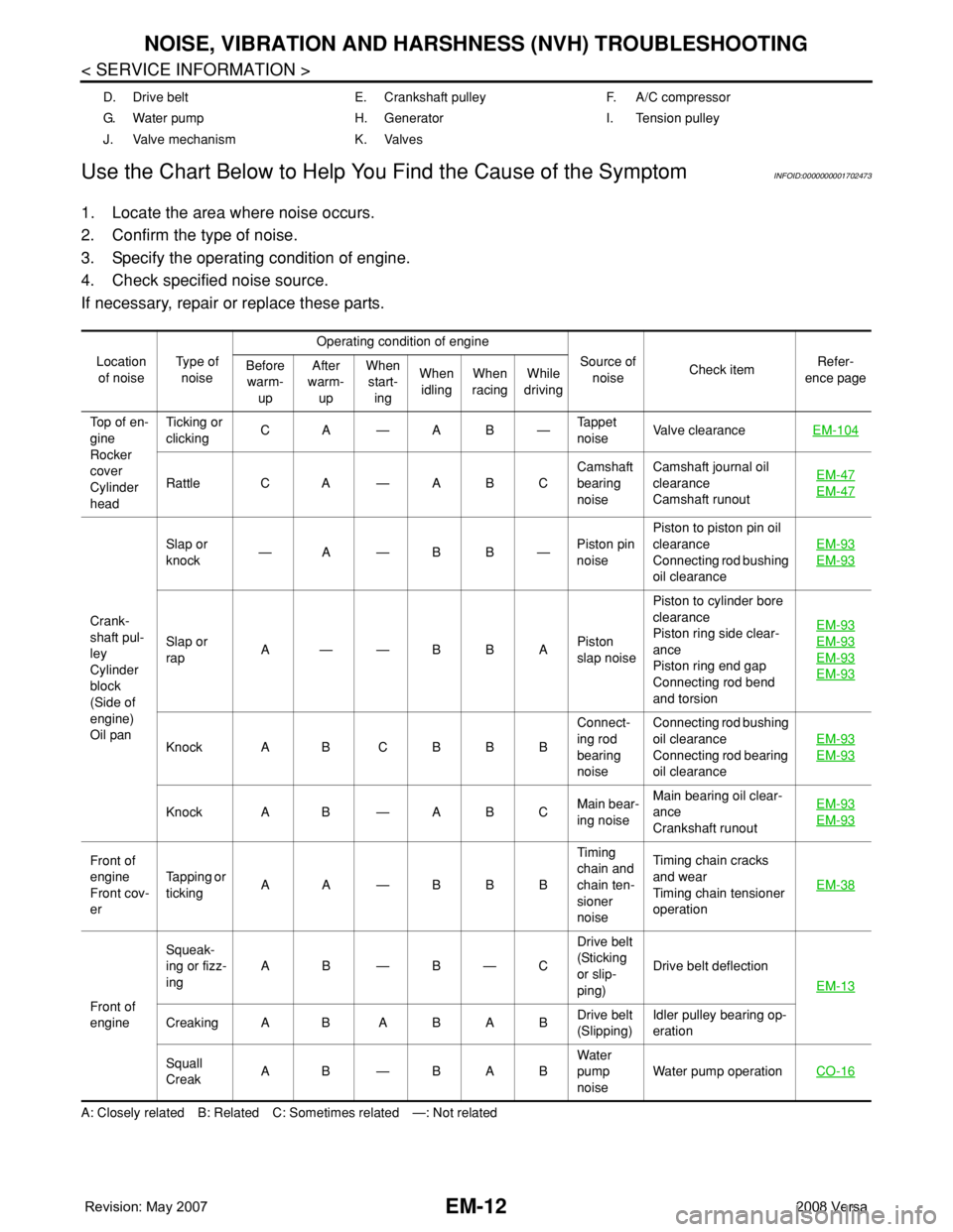
Use the Chart Below to Help You Find the Cause of the Symptom
INFOID:0000000001702473
1. Locate the area where noise occurs.
2. Confirm the type of noise.
3. Specify the operating condition of engine.
4. Check specified noise source.
If necessary, repair or replace these parts.
A: Closely related B: Related C: Sometimes related —: Not relatedD. Drive belt E. Crankshaft pulley F. A/C compressor
G. Water pump H. Generator I. Tension pulley
J. Valve mechanism K. Valves
Location
of noiseTyp e of
noiseOperating condition of engine
Source of
noiseCheck itemRefer-
ence page Before
warm-
upAfter
warm-
upWhen
start-
ingWhen
idlingWhen
racingWhile
driving
Top of en-
gine
Rocker
cover
Cylinder
headTicking or
clickingCA—AB—Tappet
noiseValve clearanceEM-104
Rattle C A — A B CCamshaft
bearing
noiseCamshaft journal oil
clearance
Camshaft runoutEM-47EM-47
Crank-
shaft pul-
ley
Cylinder
block
(Side of
engine)
Oil panSlap or
knock—A—BB—Piston pin
noisePiston to piston pin oil
clearance
Connecting rod bushing
oil clearanceEM-93
EM-93
Slap or
rapA——BBAPiston
slap noisePiston to cylinder bore
clearance
Piston ring side clear-
ance
Piston ring end gap
Connecting rod bend
and torsionEM-93EM-93
EM-93
EM-93
Knock A B C B B BConnect-
ing rod
bearing
noiseConnecting rod bushing
oil clearance
Connecting rod bearing
oil clearanceEM-93EM-93
Knock A B — A B CMain bear-
ing noiseMain bearing oil clear-
ance
Crankshaft runoutEM-93EM-93
Front of
engine
Front cov-
erTapping or
tickingAA—BBBTiming
chain and
chain ten-
sioner
noiseTiming chain cracks
and wear
Timing chain tensioner
operationEM-38
Front of
engineSqueak-
ing or fizz-
ingAB—B—CDrive belt
(Sticking
or slip-
ping)Drive belt deflection
EM-13
Creaking A B A B A BDrive belt
(Slipping)Idler pulley bearing op-
eration
Squall
CreakAB—BABWater
pump
noiseWater pump operationCO-16
Page 1690 of 2771
DRIVE BELTS
EM-13
< SERVICE INFORMATION >
C
D
E
F
G
H
I
J
K
L
MA
EM
N
P O
DRIVE BELTS
ComponentINFOID:0000000001702474
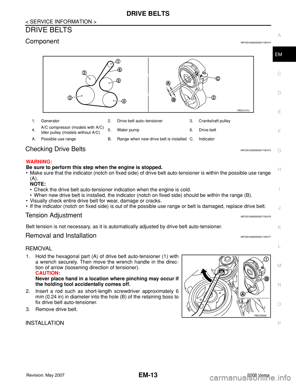
Checking Drive BeltsINFOID:0000000001702475
WARNING:
Be sure to perform this step when the engine is stopped.
• Make sure that the indicator (notch on fixed side) of drive belt auto-tensioner is within the possible use range
(A).
NOTE:
• Check the drive belt auto-tensioner indication when the engine is cold.
• When new drive belt is installed, the indicator (notch on fixed side) should be within the range (B).
• Visually check entire drive belt for wear, damage or cracks.
• If the indicator (notch on fixed side) is out of the possible use range or belt is damaged, replace drive belt.
Tension AdjustmentINFOID:0000000001702476
Belt tension is not necessary, as it is automatically adjusted by drive belt auto-tensioner.
Removal and InstallationINFOID:0000000001702477
REMOVAL
1. Hold the hexagonal part (A) of drive belt auto-tensioner (1) with
a wrench securely. Then move the wrench handle in the direc-
tion of arrow (loosening direction of tensioner).
CAUTION:
Never place hand in a location where pinching may occur if
the holding tool accidentally comes off.
2. Insert a rod such as short-length screwdriver approximately 6
mm (0.24 in) in diameter into the hole (B) of the retaining boss to
fix drive belt auto-tensioner.
3. Remove drive belt.
INSTALLATION
1. Generator 2. Drive belt auto–tensioner 3. Crankshaft pulley
4.A/C compressor (models with A/C)
Idler pulley (models without A/C)5. Water pump 6. Drive belt
A. Possible use range B. Range when new drive belt is installed C. Indicator
PBIC3137J
PBIC3936E
Page 1691 of 2771
EM-14
< SERVICE INFORMATION >
DRIVE BELTS
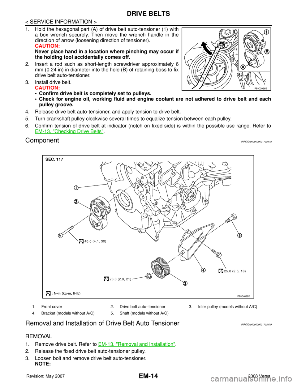
1. Hold the hexagonal part (A) of drive belt auto-tensioner (1) with
a box wrench securely. Then move the wrench handle in the
direction of arrow (loosening direction of tensioner).
CAUTION:
Never place hand in a location where pinching may occur if
the holding tool accidentally comes off.
2. Insert a rod such as short-length screwdriver approximately 6
mm (0.24 in) in diameter into the hole (B) of retaining boss to fix
drive belt auto-tensioner.
3. Install drive belt.
CAUTION:
• Confirm drive belt is completely set to pulleys.
• Check for engine oil, working fluid and engine coolant are not adhered to drive belt and each
pulley groove.
4. Release drive belt auto-tensioner, and apply tension to drive belt.
5. Turn crankshaft pulley clockwise several times to equalize tension between each pulley.
6. Confirm tension of drive belt at indicator (notch on fixed side) is within the possible use range. Refer to
EM-13, "
Checking Drive Belts".
ComponentINFOID:0000000001702478
Removal and Installation of Drive Belt Auto TensionerINFOID:0000000001702479
REMOVAL
1. Remove drive belt. Refer to EM-13, "Removal and Installation".
2. Release the fixed drive belt auto-tensioner pulley.
3. Loosen bolt and remove drive belt auto-tensioner.
NOTE:
PBIC3936E
1. Front cover 2. Drive belt auto–tensioner 3. Idler pulley (models without A/C)
4. Bracket (models without A/C) 5. Shaft (models without A/C)
PBIC4698E
Page 1697 of 2771
EM-20
< SERVICE INFORMATION >
INTAKE MANIFOLD
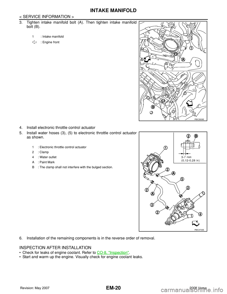
3. Tighten intake manifold bolt (A). Then tighten intake manifold
bolt (B).
4. Install electronic throttle control actuator
5. Install water hoses (3), (5) to electronic throttle control actuator
as shown.
6. Installation of the remaining components is in the reverse order of removal.
INSPECTION AFTER INSTALLATION
• Check for leaks of engine coolant. Refer to CO-8, "Inspection".
• Start and warm up the engine. Visually check for engine coolant leaks.
1 : Intake manifold
: Engine front
PBIC3939E
1 : Electronic throttle control actuator
2: Clamp
4 : Water outlet
A: Paint Mark
B : The clamp shall not interfere with the bulged section.
PBIC4703E