2008 NISSAN TIIDA check engine
[x] Cancel search: check enginePage 1509 of 2771
DTC P1564 ASCD STEERING SWITCH
EC-435
< SERVICE INFORMATION >
C
D
E
F
G
H
I
J
K
L
MA
EC
N
P O
Diagnosis ProcedureINFOID:0000000001702956
1.CHECK GROUND CONNECTIONS
1. Turn ignition switch OFF.
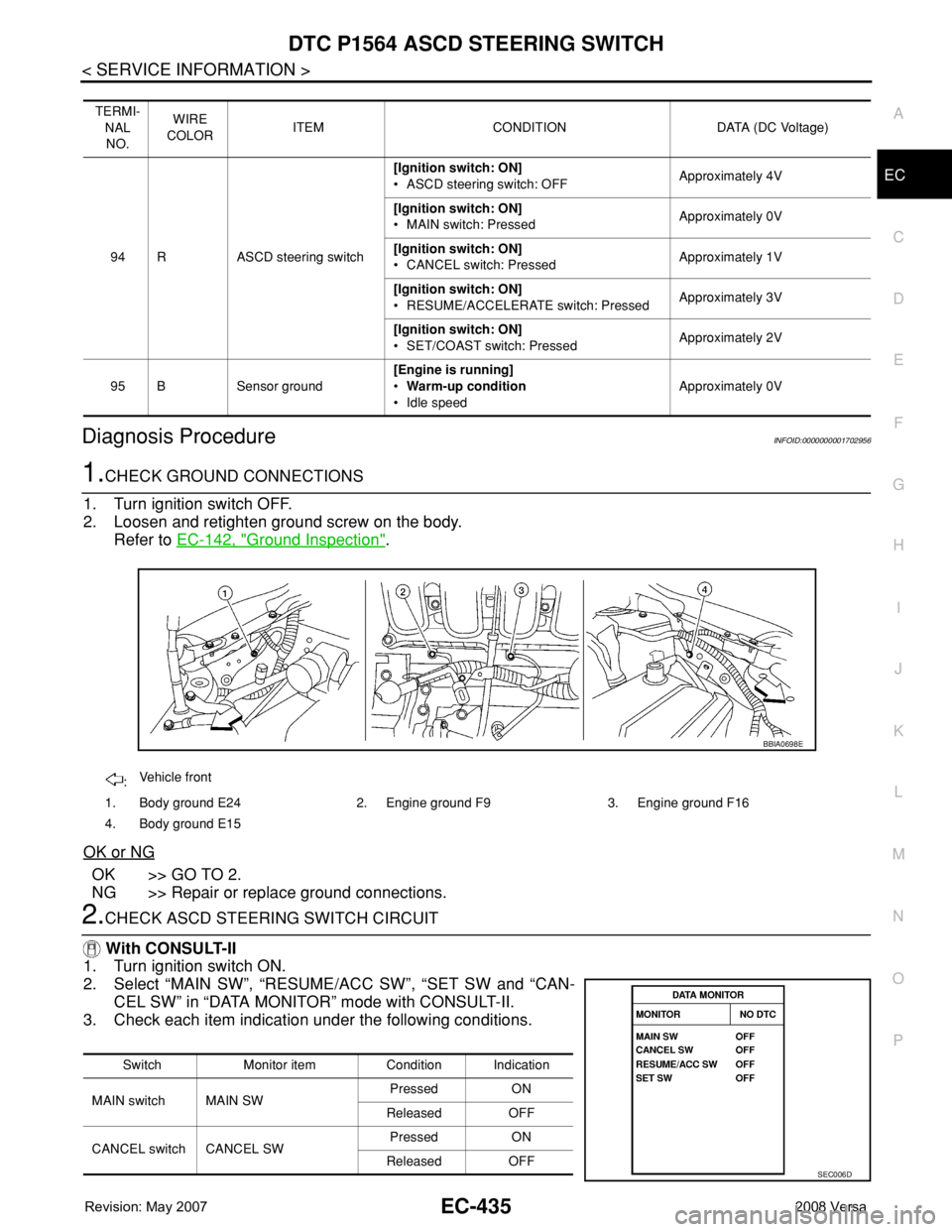
2. Loosen and retighten ground screw on the body.
Refer to EC-142, "
Ground Inspection".
OK or NG
OK >> GO TO 2.
NG >> Repair or replace ground connections.
2.CHECK ASCD STEERING SWITCH CIRCUIT
With CONSULT-II
1. Turn ignition switch ON.
2. Select “MAIN SW”, “RESUME/ACC SW”, “SET SW and “CAN-
CEL SW” in “DATA MONITOR” mode with CONSULT-II.
3. Check each item indication under the following conditions.
TERMI-
NAL
NO.WIRE
COLORITEM CONDITION DATA (DC Voltage)
94 R ASCD steering switch[Ignition switch: ON]
• ASCD steering switch: OFFApproximately 4V
[Ignition switch: ON]
• MAIN switch: PressedApproximately 0V
[Ignition switch: ON]
• CANCEL switch: PressedApproximately 1V
[Ignition switch: ON]
• RESUME/ACCELERATE switch: PressedApproximately 3V
[Ignition switch: ON]
• SET/COAST switch: PressedApproximately 2V
95 B Sensor ground[Engine is running]
•Warm-up condition
• Idle speedApproximately 0V
:Vehicle front
1. Body ground E24 2. Engine ground F9 3. Engine ground F16
4. Body ground E15
BBIA0698E
Switch Monitor item Condition Indication
MAIN switch MAIN SWPressed ON
Released OFF
CANCEL switch CANCEL SWPressed ON
Released OFF
SEC006D
Page 1523 of 2771
DTC P1715 INPUT SPEED SENSOR (TURBINE REVOLUTION SENSOR)
EC-449
< SERVICE INFORMATION >
C
D
E
F
G
H
I
J
K
L
MA
EC
N
P O
DTC P1715 INPUT SPEED SENSOR (TURBINE REVOLUTION SENSOR)
DescriptionINFOID:0000000001702969
ECM receives turbine revolution sensor signal from TCM through CAN communication line. ECM uses this
signal for engine control.
CONSULT-II Reference Value in Data Monitor ModeINFOID:0000000001702970
Specification data are reference values.
On Board Diagnosis LogicINFOID:0000000001702971
NOTE:
•If DTC P1715 is displayed with DTC U1000, U1001 first perform the trouble diagnosis for DTC U1000,
U1001. Refer to EC-143
.
•If DTC P1715 is displayed with DTC U1010, first perform the trouble diagnosis for DTC U1010. Refer
to EC-145
.
•If DTC P1715 is displayed with DTC P0335, first perform the trouble diagnosis for DTC P0335. Refer
to EC-295
.
•If DTC P1715 is displayed with DTC P0340 first perform the trouble diagnosis for DTC P0340.
Refer to EC-302
.
•If DTC P1715 is displayed with DTC P0605, first perform the trouble diagnosis for DTC P0605. Refer
to EC-397
.
The MIL will not lights up for this diagnosis.
Diagnosis ProcedureINFOID:0000000001702972
1.CHECK DTC WITH TCM
Check DTC with TCM. Refer to AT- 3 6
.
OK or NG
OK >> GO TO 2.
NG >> Perform trouble shooting relevant to DTC indicated.
2.REPLACE TCM
Replace TCM. Refer to AT- 3 9
.
>>INSPECTION END
MONITOR ITEM CONDITION SPECIFICATION
I/P PULLY SPD • Vehicle speed: More than 20 km/h (12MPH)Almost the same speed as the
tachometer indication
DTC No. Trouble diagnosis name DTC detecting condition Possible cause
P1715
1715Input speed sensor
(Turbine revolution sen-
sor)
(TCM output)Turbine revolution sensor signal is differ-
ent from the theoretical value calculated
by ECM from revolution sensor signal and
engine rpm signal.• Harness or connectors
(CAN communication line is open or shorted)
• Harness or connectors
(Turbine revolution sensor circuit is open or
shorted)
•TCM
Page 1533 of 2771
DTC P2100, P2103 THROTTLE CONTROL MOTOR RELAY
EC-459
< SERVICE INFORMATION >
C
D
E
F
G
H
I
J
K
L
MA
EC
N
P O
Do not use ECM ground terminals when measuring input/output voltage. Doing so may result in dam-
age to the ECM's transistor. Use a ground other than ECM terminals, such as the ground.
: Average voltage for pulse signal (Actual pulse signal can be confirmed by oscilloscope.)
Diagnosis ProcedureINFOID:0000000001702990
1.CHECK THROTTLE CONTROL MOTOR RELAY POWER SUPPLY CIRCUIT-I
1. Turn ignition switch OFF.
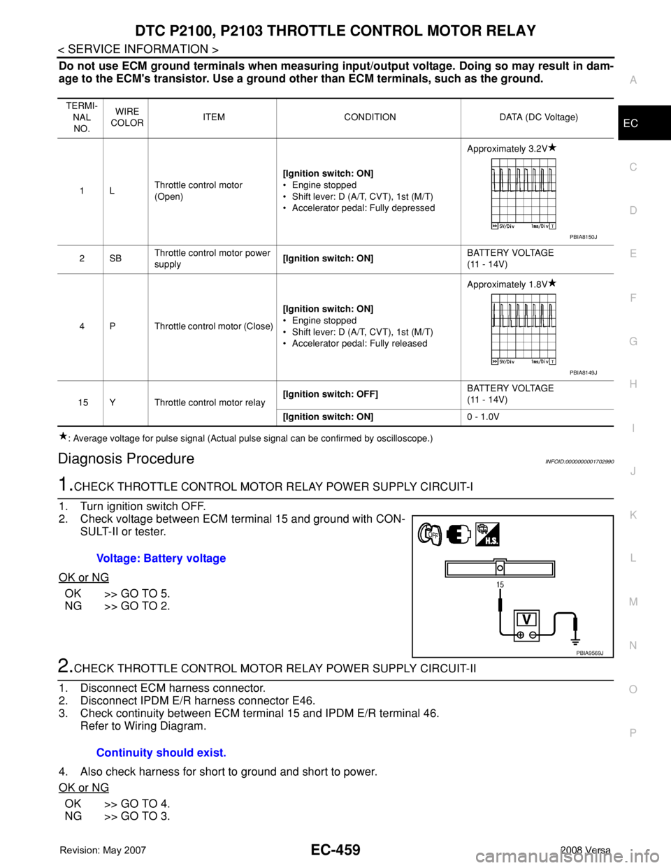
2. Check voltage between ECM terminal 15 and ground with CON-
SULT-II or tester.
OK or NG
OK >> GO TO 5.
NG >> GO TO 2.
2.CHECK THROTTLE CONTROL MOTOR RELAY POWER SUPPLY CIRCUIT-II
1. Disconnect ECM harness connector.
2. Disconnect IPDM E/R harness connector E46.
3. Check continuity between ECM terminal 15 and IPDM E/R terminal 46.
Refer to Wiring Diagram.
4. Also check harness for short to ground and short to power.
OK or NG
OK >> GO TO 4.
NG >> GO TO 3.
TERMI-
NAL
NO.WIRE
COLORITEM CONDITION DATA (DC Voltage)
1LThrottle control motor
(Open)[Ignition switch: ON]
• Engine stopped
• Shift lever: D (A/T, CVT), 1st (M/T)
• Accelerator pedal: Fully depressedApproximately 3.2V
2SBThrottle control motor power
supply[Ignition switch: ON]BATTERY VOLTAGE
(11 - 14V)
4 P Throttle control motor (Close)[Ignition switch: ON]
• Engine stopped
• Shift lever: D (A/T, CVT), 1st (M/T)
• Accelerator pedal: Fully releasedApproximately 1.8V
15 Y Throttle control motor relay[Ignition switch: OFF]BATTERY VOLTAGE
(11 - 14V)
[Ignition switch: ON]0 - 1.0V
PBIA8150J
PBIA8149J
Voltage: Battery voltage
PBIA9569J
Continuity should exist.
Page 1537 of 2771
DTC P2101 ELECTRIC THROTTLE CONTROL FUNCTION
EC-463
< SERVICE INFORMATION >
C
D
E
F
G
H
I
J
K
L
MA
EC
N
P O
Do not use ECM ground terminals when measuring input/output voltage. Doing so may result in dam-
age to the ECM's transistor. Use a ground other than ECM terminals, such as the ground.
: Average voltage for pulse signal (Actual pulse signal can be confirmed by oscilloscope.)
Diagnosis ProcedureINFOID:0000000001702995
1.CHECK GROUND CONNECTIONS
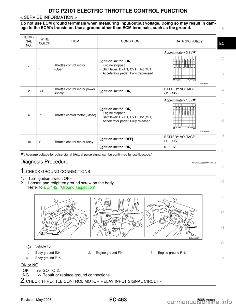
1. Turn ignition switch OFF.
2. Loosen and retighten ground screw on the body.
Refer to EC-142, "
Ground Inspection".
OK or NG
OK >> GO TO 2.
NG >> Repair or replace ground connections.
2.CHECK THROTTLE CONTROL MOTOR RELAY INPUT SIGNAL CIRCUIT-I
TERMI-
NAL
NO.WIRE
COLORITEM CONDITION DATA (DC Voltage)
1LThrottle control motor
(Open)[Ignition switch: ON]
• Engine stopped
• Shift lever: D (A/T, CVT), 1st (M/T)
• Accelerator pedal: Fully depressedApproximately 3.2V
2SBThrottle control motor power
supply[Ignition switch: ON]BATTERY VOLTAGE
(11 - 14V)
4 P Throttle control motor (Close)[Ignition switch: ON]
• Engine stopped
• Shift lever: D (A/T, CVT), 1st (M/T)
• Accelerator pedal: Fully releasedApproximately 1.8V
15 Y Throttle control motor relay[Ignition switch: OFF]BATTERY VOLTAGE
(11 - 14V)
[Ignition switch: ON]0 - 1.0V
PBIA8150J
PBIA8149J
:Vehicle front
1. Body ground E24 2. Engine ground F9 3. Engine ground F16
4. Body ground E15
BBIA0698E
Page 1543 of 2771
DTC P2118 THROTTLE CONTROL MOTOR
EC-469
< SERVICE INFORMATION >
C
D
E
F
G
H
I
J
K
L
MA
EC
N
P O
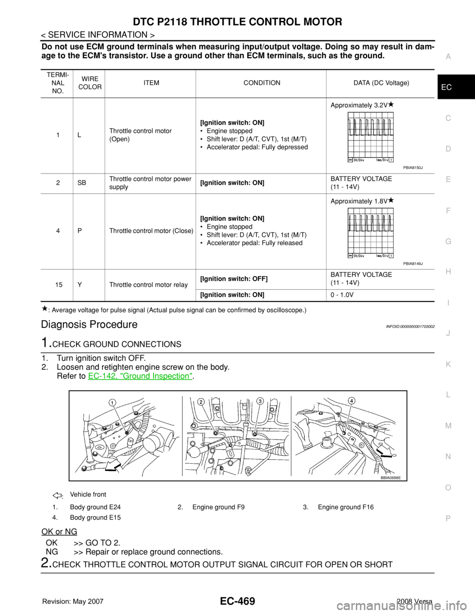
Do not use ECM ground terminals when measuring input/output voltage. Doing so may result in dam-
age to the ECM's transistor. Use a ground other than ECM terminals, such as the ground.
: Average voltage for pulse signal (Actual pulse signal can be confirmed by oscilloscope.)
Diagnosis ProcedureINFOID:0000000001703002
1.CHECK GROUND CONNECTIONS
1. Turn ignition switch OFF.
2. Loosen and retighten engine screw on the body.
Refer to EC-142, "
Ground Inspection".
OK or NG
OK >> GO TO 2.
NG >> Repair or replace ground connections.
2.CHECK THROTTLE CONTROL MOTOR OUTPUT SIGNAL CIRCUIT FOR OPEN OR SHORT
TERMI-
NAL
NO.WIRE
COLORITEM CONDITION DATA (DC Voltage)
1LThrottle control motor
(Open)[Ignition switch: ON]
• Engine stopped
• Shift lever: D (A/T, CVT), 1st (M/T)
• Accelerator pedal: Fully depressedApproximately 3.2V
2SBThrottle control motor power
supply[Ignition switch: ON]BATTERY VOLTAGE
(11 - 14V)
4 P Throttle control motor (Close)[Ignition switch: ON]
• Engine stopped
• Shift lever: D (A/T, CVT), 1st (M/T)
• Accelerator pedal: Fully releasedApproximately 1.8V
15 Y Throttle control motor relay[Ignition switch: OFF]BATTERY VOLTAGE
(11 - 14V)
[Ignition switch: ON]0 - 1.0V
PBIA8150J
PBIA8149J
:Vehicle front
1. Body ground E24 2. Engine ground F9 3. Engine ground F16
4. Body ground E15
BBIA0698E
Page 1547 of 2771
DTC P2119 ELECTRIC THROTTLE CONTROL ACTUATOR
EC-473
< SERVICE INFORMATION >
C
D
E
F
G
H
I
J
K
L
MA
EC
N
P O
10. If DTC is detected, go to EC-473, "Diagnosis Procedure".
With GST
Follow the procedure “With CONSULT-II” above.
PROCEDURE FOR MALFUNCTION C
With CONSULT-II
1. Turn ignition switch ON and wait at least 1 second.
2. Select “DATA MONITOR” mode with CONSULT-II.
3. Set shift lever to D position (A/T, CVT) or 1st position (M/T) and
wait at least 3 seconds.
4. Set shift lever to N, P position (A/T, CVT) or Neutral (M/T) posi-
tion.
5. Start engine and let it idle for 3 seconds.
6. If DTC is detected, go to EC-473, "
Diagnosis Procedure".
With GST
Follow the procedure “With CONSULT-II” above.
Diagnosis ProcedureINFOID:0000000001703008
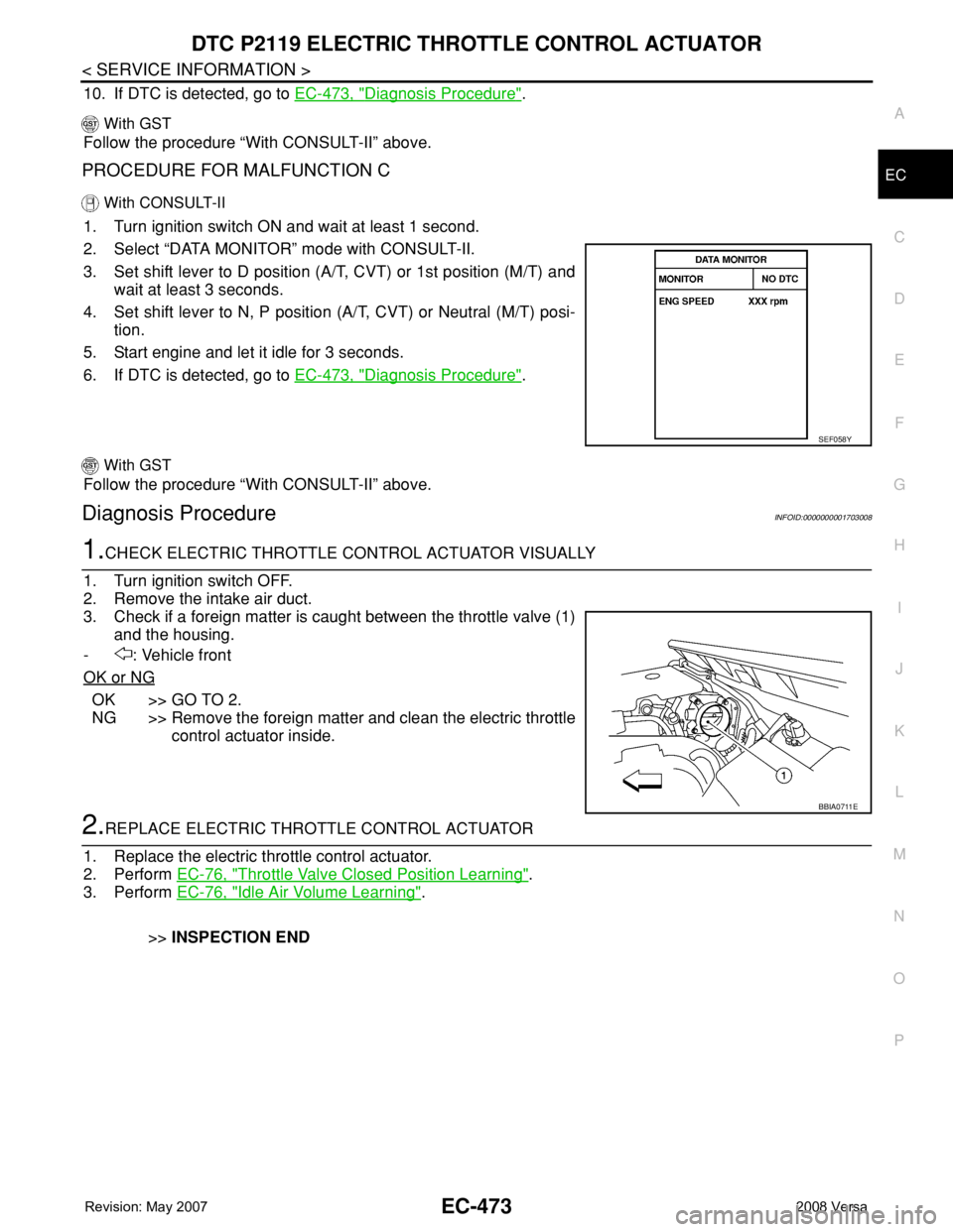
1.CHECK ELECTRIC THROTTLE CONTROL ACTUATOR VISUALLY
1. Turn ignition switch OFF.
2. Remove the intake air duct.
3. Check if a foreign matter is caught between the throttle valve (1)
and the housing.
- : Vehicle front
OK or NG
OK >> GO TO 2.
NG >> Remove the foreign matter and clean the electric throttle
control actuator inside.
2.REPLACE ELECTRIC THROTTLE CONTROL ACTUATOR
1. Replace the electric throttle control actuator.
2. Perform EC-76, "
Throttle Valve Closed Position Learning".
3. Perform EC-76, "
Idle Air Volume Learning".
>>INSPECTION END
SEF058Y
BBIA0711E
Page 1551 of 2771
DTC P2122, P2123 APP SENSOR
EC-477
< SERVICE INFORMATION >
C
D
E
F
G
H
I
J
K
L
MA
EC
N
P O
Diagnosis ProcedureINFOID:0000000001703014
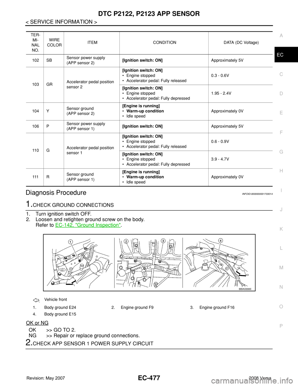
1.CHECK GROUND CONNECTIONS
1. Turn ignition switch OFF.
2. Loosen and retighten ground screw on the body.
Refer to EC-142, "
Ground Inspection".
OK or NG
OK >> GO TO 2.
NG >> Repair or replace ground connections.
2.CHECK APP SENSOR 1 POWER SUPPLY CIRCUIT
TER-
MI-
NAL
NO.WIRE
COLORITEM CONDITION DATA (DC Voltage)
102 SBSensor power supply
(APP sensor 2)[Ignition switch: ON]Approximately 5V
103 GRAccelerator pedal position
sensor 2[Ignition switch: ON]
• Engine stopped
• Accelerator pedal: Fully released0.3 - 0.6V
[Ignition switch: ON]
• Engine stopped
• Accelerator pedal: Fully depressed1.95 - 2.4V
104 YSensor ground
(APP sensor 2)[Engine is running]
•Warm-up condition
• Idle speedApproximately 0V
106 PSensor power supply
(APP sensor 1)[Ignition switch: ON]Approximately 5V
11 0 GAccelerator pedal position
sensor 1[Ignition switch: ON]
• Engine stopped
• Accelerator pedal: Fully released0.6 - 0.9V
[Ignition switch: ON]
• Engine stopped
• Accelerator pedal: Fully depressed3.9 - 4.7V
111 RSensor ground
(APP sensor 1)[Engine is running]
•Warm-up condition
• Idle speedApproximately 0V
:Vehicle front
1. Body ground E24 2. Engine ground F9 3. Engine ground F16
4. Body ground E15
BBIA0698E
Page 1557 of 2771
DTC P2127, P2128 APP SENSOR
EC-483
< SERVICE INFORMATION >
C
D
E
F
G
H
I
J
K
L
MA
EC
N
P O
Diagnosis ProcedureINFOID:0000000001703022
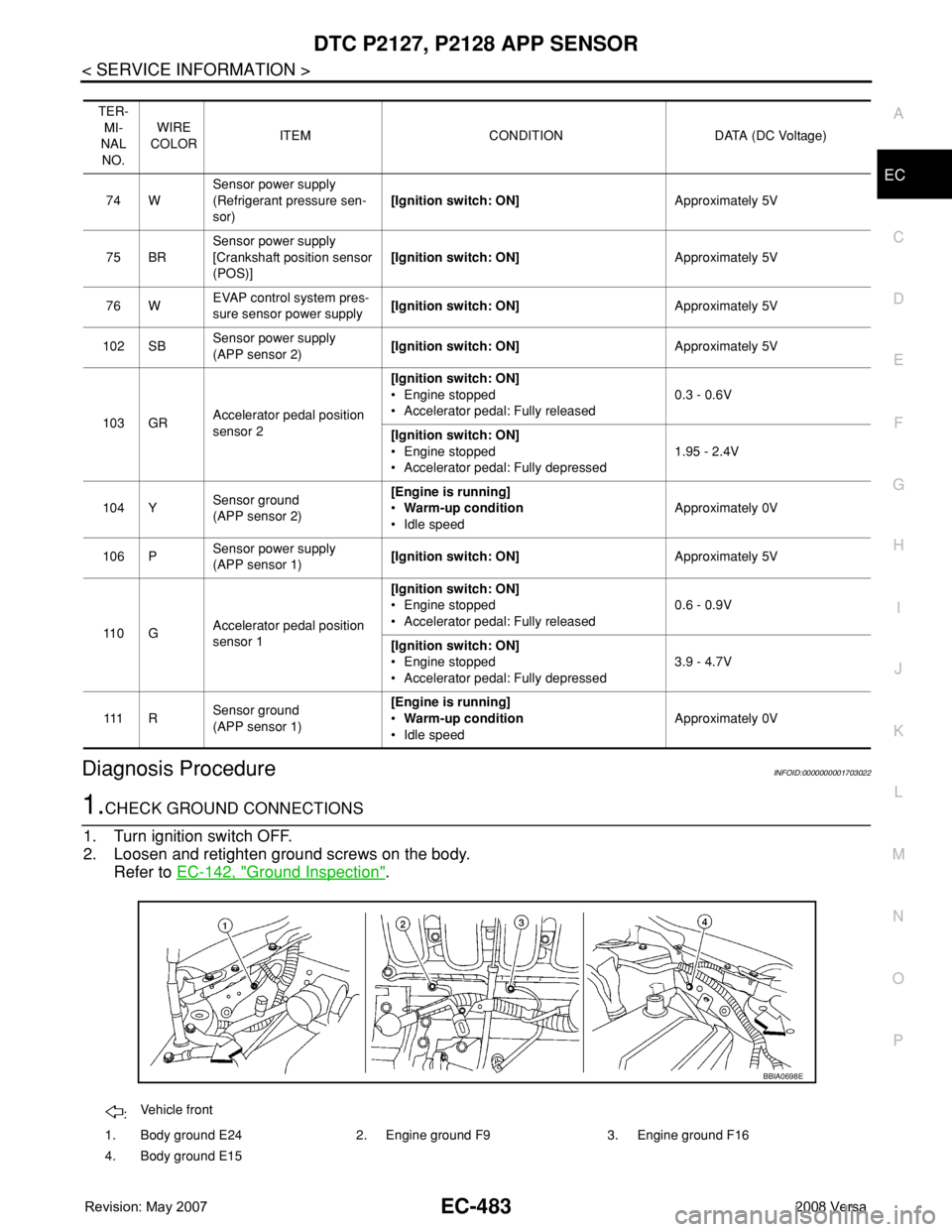
1.CHECK GROUND CONNECTIONS
1. Turn ignition switch OFF.
2. Loosen and retighten ground screws on the body.
Refer to EC-142, "
Ground Inspection".
TER-
MI-
NAL
NO.WIRE
COLORITEM CONDITION DATA (DC Voltage)
74 WSensor power supply
(Refrigerant pressure sen-
sor)[Ignition switch: ON]Approximately 5V
75 BRSensor power supply
[Crankshaft position sensor
(POS)][Ignition switch: ON]Approximately 5V
76 WEVAP control system pres-
sure sensor power supply[Ignition switch: ON]Approximately 5V
102 SBSensor power supply
(APP sensor 2)[Ignition switch: ON]Approximately 5V
103 GRAccelerator pedal position
sensor 2[Ignition switch: ON]
• Engine stopped
• Accelerator pedal: Fully released0.3 - 0.6V
[Ignition switch: ON]
• Engine stopped
• Accelerator pedal: Fully depressed1.95 - 2.4V
104 YSensor ground
(APP sensor 2)[Engine is running]
•Warm-up condition
• Idle speedApproximately 0V
106 PSensor power supply
(APP sensor 1)[Ignition switch: ON]Approximately 5V
11 0 GAccelerator pedal position
sensor 1[Ignition switch: ON]
• Engine stopped
• Accelerator pedal: Fully released0.6 - 0.9V
[Ignition switch: ON]
• Engine stopped
• Accelerator pedal: Fully depressed3.9 - 4.7V
111 RSensor ground
(APP sensor 1)[Engine is running]
•Warm-up condition
• Idle speedApproximately 0V
:Vehicle front
1. Body ground E24 2. Engine ground F9 3. Engine ground F16
4. Body ground E15
BBIA0698E