Page 1699 of 2771
EM-22
< SERVICE INFORMATION >
EXHAUST MANIFOLD
5. Loosen nuts in reverse order as shown and remove exhaust
manifold.
CAUTION:
Cover engine openings to avoid entry of foreign materials.
INSPECTION AFTER REMOVAL
Surface Distortion
• Using straightedge (B) and feeler gauge (A), check the surface dis-
tortion of exhaust manifold mating surface in each exhaust port
and entire part.
• If it exceeds the limit, replace exhaust manifold.
INSTALLATION
1. Install exhaust manifold gasket to cylinder head as shown.
2. Tighten exhaust manifold nuts to specification in two stages in
the numerical order as shown.
: Engine front
PBIC3529J
Limit:
Each exhaust port : 0.3 mm (0.012 in)
Entire part : 0.7 mm (0.028 in)
PBIC3530J
: Engine front
PBIC3943E
: Engine front
PBIC3529J
Page 1708 of 2771
IGNITION COIL, SPARK PLUG AND ROCKER COVER
EM-31
< SERVICE INFORMATION >
C
D
E
F
G
H
I
J
K
L
MA
EM
N
P O
3. Remove spark plug using suitable tool.
CAUTION:
Never drop or shock it.
4. Remove rocker cover.
• Loosen bolts in reverse order as shown.
• Engine front
INSPECTION AFTER REMOVAL
CAUTION:
• Never drop or shock spark plug.
• Checking and adjusting spark plug gap is not required
between change intervals.
• If spark plug tip is covered with carbon, a spark plug cleaner may be used.
• Never use wire brush for cleaning spark plug.
INSTALLATION
1. Install rocker cover gasket to rocker cover.
PBIC3871E
PBIC3151J
SMA806CA
Cleaner air pressure
: Less than 588 kPa (5.88 bar, 6 kg/cm2, 85 psi)
Cleaning time : Less than 20 seconds
SMA773C
Page 1709 of 2771
EM-32
< SERVICE INFORMATION >
IGNITION COIL, SPARK PLUG AND ROCKER COVER
2. Install rocker cover.
• Tighten bolts in two steps separately in numerical order as
shown.
• Engine front
CAUTION:
Check if rocker cover gasket is not dropped from the instal-
lation groove of rocker cover.
3. Install spark plug using suitable tool.
CAUTION:
Never drop or shock it.
4. Install ignition coil.
CAUTION:
• Handle it carefully and avoid impacts.
• Never disassemble.
5. Install intake manifold. Refer to EM-18
. 1st step : 1.96 N·m (0.20 kg-m, 17 in-lb)
2nd step : 8.33 N·m (0.85 kg-m, 73 in-lb)
PBIC3151J
Plug type : Iridium tipped
Make : DENSO
Part number : FXE20HR11
Gap (nominal) : 1.1 mm (0.043 in)
PBIC3871E
Page 1720 of 2771

TIMING CHAIN
EM-43
< SERVICE INFORMATION >
C
D
E
F
G
H
I
J
K
L
MA
EM
N
P O
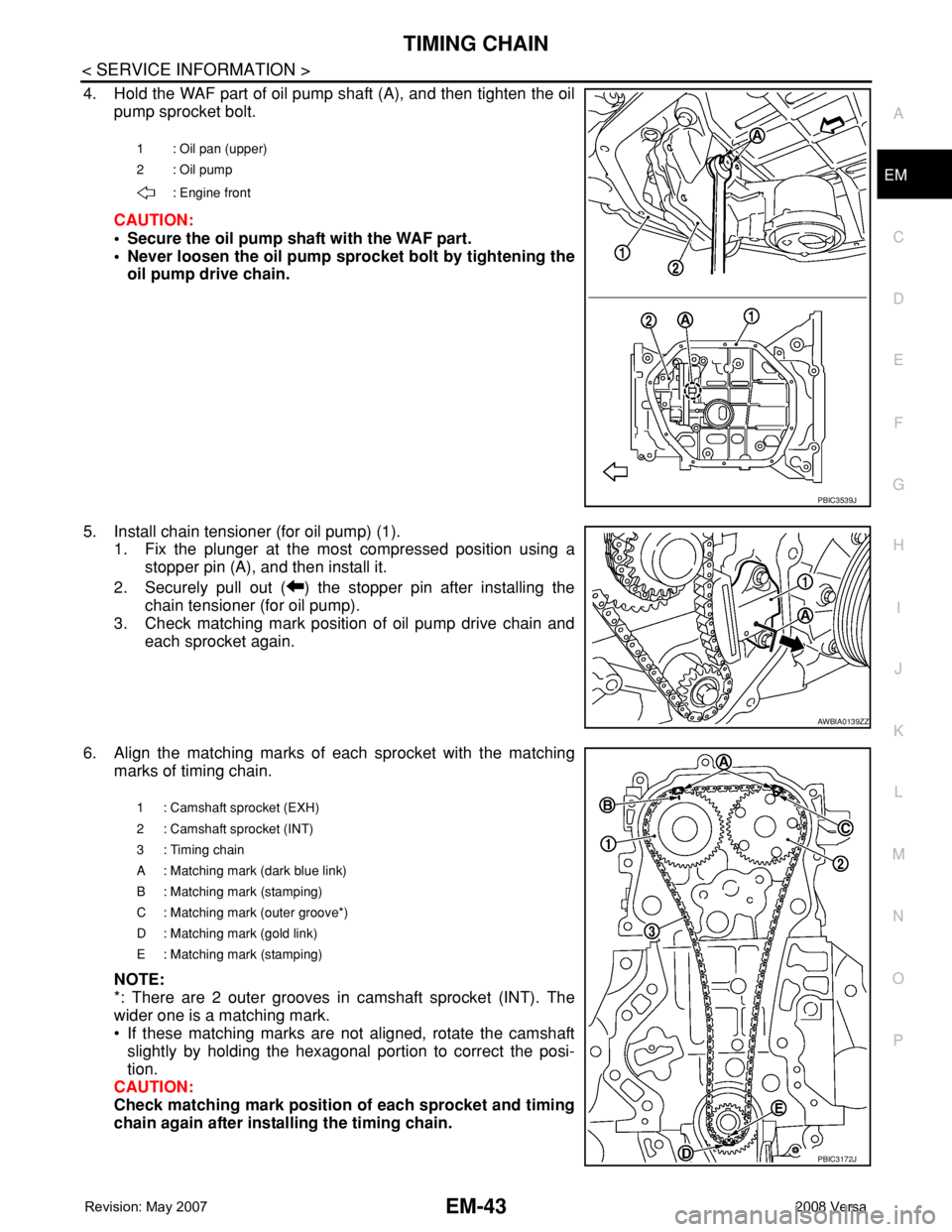
4. Hold the WAF part of oil pump shaft (A), and then tighten the oil
pump sprocket bolt.
CAUTION:
• Secure the oil pump shaft with the WAF part.
• Never loosen the oil pump sprocket bolt by tightening the
oil pump drive chain.
5. Install chain tensioner (for oil pump) (1).
1. Fix the plunger at the most compressed position using a
stopper pin (A), and then install it.
2. Securely pull out ( ) the stopper pin after installing the
chain tensioner (for oil pump).
3. Check matching mark position of oil pump drive chain and
each sprocket again.
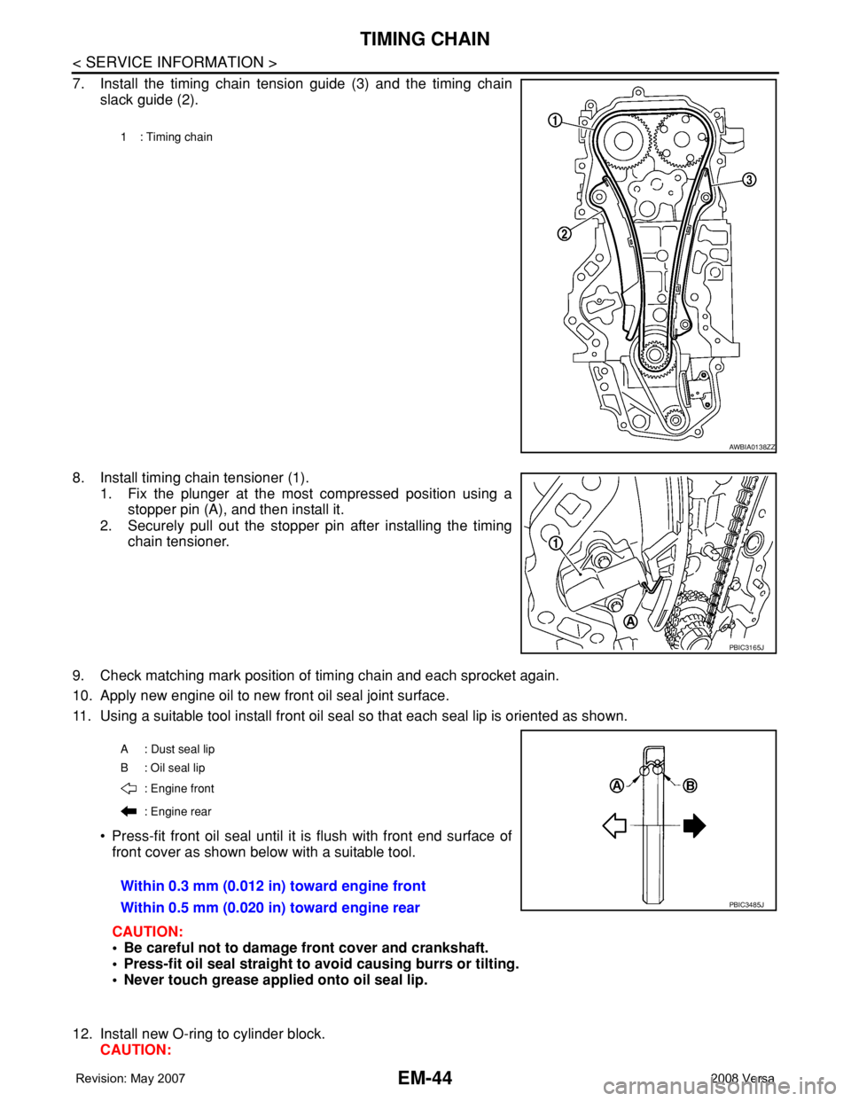
6. Align the matching marks of each sprocket with the matching
marks of timing chain.
NOTE:
*: There are 2 outer grooves in camshaft sprocket (INT). The
wider one is a matching mark.
• If these matching marks are not aligned, rotate the camshaft
slightly by holding the hexagonal portion to correct the posi-
tion.
CAUTION:
Check matching mark position of each sprocket and timing
chain again after installing the timing chain.
1 : Oil pan (upper)
2 : Oil pump
: Engine front
PBIC3539J
AWBIA0139ZZ
1 : Camshaft sprocket (EXH)
2 : Camshaft sprocket (INT)
3: Timing chain
A : Matching mark (dark blue link)
B : Matching mark (stamping)
C : Matching mark (outer groove*)
D : Matching mark (gold link)
E : Matching mark (stamping)
PBIC3172J
Page 1721 of 2771

EM-44
< SERVICE INFORMATION >
TIMING CHAIN
7. Install the timing chain tension guide (3) and the timing chain
slack guide (2).
8. Install timing chain tensioner (1).
1. Fix the plunger at the most compressed position using a
stopper pin (A), and then install it.
2. Securely pull out the stopper pin after installing the timing
chain tensioner.
9. Check matching mark position of timing chain and each sprocket again.
10. Apply new engine oil to new front oil seal joint surface.
11. Using a suitable tool install front oil seal so that each seal lip is oriented as shown.
• Press-fit front oil seal until it is flush with front end surface of
front cover as shown below with a suitable tool.
CAUTION:
• Be careful not to damage front cover and crankshaft.
• Press-fit oil seal straight to avoid causing burrs or tilting.
• Never touch grease applied onto oil seal lip.
12. Install new O-ring to cylinder block.
CAUTION:
1 : Timing chain
AWBIA0138ZZ
PBIC3165J
A : Dust seal lip
B: Oil seal lip
: Engine front
: Engine rear
Within 0.3 mm (0.012 in) toward engine front
Within 0.5 mm (0.020 in) toward engine rear
PBIC3485J
Page 1723 of 2771
EM-46
< SERVICE INFORMATION >
TIMING CHAIN
18. Secure crankshaft pulley (1) using Tool (A).
19. Apply new engine oil to thread and seat surfaces of crankshaft
pulley bolt.
20. Tighten crankshaft pulley bolt in three steps.
21. Put a paint mark (B) on crankshaft pulley (2), matching with any
one of six easy to recognize angle marks (A) on crankshaft pul-
ley bolt flange (1).
22. Turn another 60 degrees clockwise (angle tightening) using
Tool.
• Check the tightening angle with movement of one angle mark.
23. Make sure that crankshaft rotates clockwise smoothly.
24. Installation of the remaining components is in the reverse order of removal.Tool Number (A) : KV10109300 ( — )
Step 1 : 68.6 N·m (7.0 kg-m, 51 ft-lb)
Step 2 : 0 N·m (0 kg-m, 0 ft-lb)
Step 3 : 29.4 N·m (3.0 kg-m, 22 ft-lb)
PBIC3961E
Tool number : KV10112100 (BT-8653-A)
PBIC3963E
Page 1724 of 2771

CAMSHAFT
EM-47
< SERVICE INFORMATION >
C
D
E
F
G
H
I
J
K
L
MA
EM
N
P O
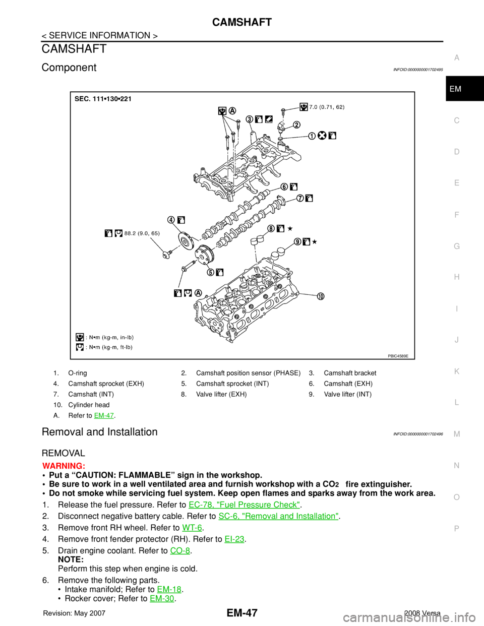
CAMSHAFT
ComponentINFOID:0000000001702495
Removal and InstallationINFOID:0000000001702496
REMOVAL
WARNING:
• Put a “CAUTION: FLAMMABLE” sign in the workshop.
• Be sure to work in a well ventilated area and furnish workshop with a CO
2 fire extinguisher.
• Do not smoke while servicing fuel system. Keep open flames and sparks away from the work area.
1. Release the fuel pressure. Refer to EC-78, "
Fuel Pressure Check".
2. Disconnect negative battery cable. Refer to SC-6, "
Removal and Installation".
3. Remove front RH wheel. Refer to WT-6
.
4. Remove front fender protector (RH). Refer to EI-23
.
5. Drain engine coolant. Refer to CO-8
.
NOTE:
Perform this step when engine is cold.
6. Remove the following parts.
• Intake manifold; Refer to EM-18
.
• Rocker cover; Refer to EM-30
.
1. O-ring 2. Camshaft position sensor (PHASE) 3. Camshaft bracket
4. Camshaft sprocket (EXH) 5. Camshaft sprocket (INT) 6. Camshaft (EXH)
7. Camshaft (INT) 8. Valve lifter (EXH) 9. Valve lifter (INT)
10. Cylinder head
A. Refer to EM-47
.
PBIC4589E
Page 1731 of 2771

EM-54
< SERVICE INFORMATION >
CAMSHAFT
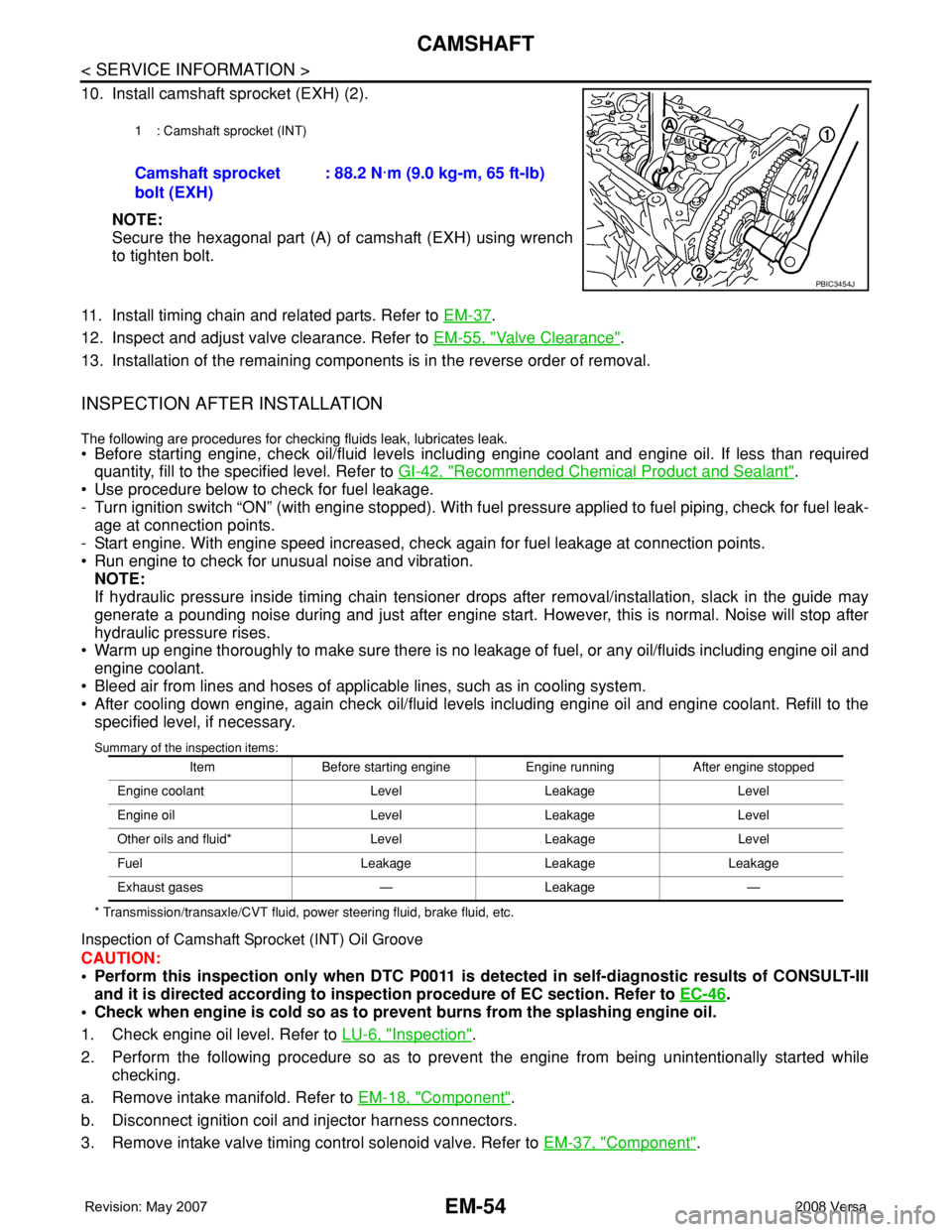
10. Install camshaft sprocket (EXH) (2).
NOTE:
Secure the hexagonal part (A) of camshaft (EXH) using wrench
to tighten bolt.
11. Install timing chain and related parts. Refer to EM-37
.
12. Inspect and adjust valve clearance. Refer to EM-55, "
Valve Clearance".
13. Installation of the remaining components is in the reverse order of removal.
INSPECTION AFTER INSTALLATION
The following are procedures for checking fluids leak, lubricates leak.
• Before starting engine, check oil/fluid levels including engine coolant and engine oil. If less than required
quantity, fill to the specified level. Refer to GI-42, "
Recommended Chemical Product and Sealant".
• Use procedure below to check for fuel leakage.
- Turn ignition switch “ON” (with engine stopped). With fuel pressure applied to fuel piping, check for fuel leak-
age at connection points.
- Start engine. With engine speed increased, check again for fuel leakage at connection points.
• Run engine to check for unusual noise and vibration.
NOTE:
If hydraulic pressure inside timing chain tensioner drops after removal/installation, slack in the guide may
generate a pounding noise during and just after engine start. However, this is normal. Noise will stop after
hydraulic pressure rises.
• Warm up engine thoroughly to make sure there is no leakage of fuel, or any oil/fluids including engine oil and
engine coolant.
• Bleed air from lines and hoses of applicable lines, such as in cooling system.
• After cooling down engine, again check oil/fluid levels including engine oil and engine coolant. Refill to the
specified level, if necessary.
Summary of the inspection items:
* Transmission/transaxle/CVT fluid, power steering fluid, brake fluid, etc.
Inspection of Camshaft Sprocket (INT) Oil Groove
CAUTION:
• Perform this inspection only when DTC P0011 is detected in self-diagnostic results of CONSULT-III
and it is directed according to inspection procedure of EC section. Refer to EC-46
.
• Check when engine is cold so as to prevent burns from the splashing engine oil.
1. Check engine oil level. Refer to LU-6, "
Inspection".
2. Perform the following procedure so as to prevent the engine from being unintentionally started while
checking.
a. Remove intake manifold. Refer to EM-18, "
Component".
b. Disconnect ignition coil and injector harness connectors.
3. Remove intake valve timing control solenoid valve. Refer to EM-37, "
Component".
1 : Camshaft sprocket (INT)
Camshaft sprocket
bolt (EXH): 88.2 N·m (9.0 kg-m, 65 ft-lb)
PBIC3454J
Item Before starting engine Engine running After engine stopped
Engine coolant Level Leakage Level
Engine oil Level Leakage Level
Other oils and fluid* Level Leakage Level
Fuel Leakage Leakage Leakage
Exhaust gases — Leakage —