2008 NISSAN TIIDA fuel injectors
[x] Cancel search: fuel injectorsPage 1098 of 2771
EC-24
< SERVICE INFORMATION >
ENGINE CONTROL SYSTEM
fuel ratio (A/F) sensor 1 in the exhaust manifold to monitor whether the engine operation is rich or lean. The
ECM adjusts the injection pulse width according to the sensor voltage signal. For more information about air
fuel ratio (A/F) sensor 1, refer to EC-213
. This maintains the mixture ratio within the range of stoichiometric
(ideal air/fuel mixture).
This stage is referred to as the closed loop control condition.
Heated oxygen sensor 2 is located downstream of the three way catalyst (manifold). Even if the switching
characteristics of air fuel ratio (A/F) sensor 1 shift, the air/fuel ratio is controlled to stoichiometric by the signal
from heated oxygen sensor 2.
Open Loop Control
The open loop system condition refers to when the ECM detects any of the following conditions. Feedback
control stops in order to maintain stabilized fuel combustion.
• Deceleration and acceleration
• High-load, high-speed operation
• Malfunction of air fuel ratio (A/F) sensor 1 or its circuit
• Insufficient activation of air fuel ratio (A/F) sensor 1 at low engine coolant temperature
• High engine coolant temperature
• During warm-up
• After shifting from N to D (A/T and CVT models)
• When starting the engine
MIXTURE RATIO SELF-LEARNING CONTROL
The mixture ratio feedback control system monitors the mixture ratio signal transmitted from air fuel ratio (A/F)
sensor 1. This feedback signal is then sent to the ECM. The ECM controls the basic mixture ratio as close to
the theoretical mixture ratio as possible. However, the basic mixture ratio is not necessarily controlled as orig-
inally designed. Both manufacturing differences (i.e., mass air flow sensor hot wire) and characteristic
changes during operation (i.e., fuel injector clogging) directly affect mixture ratio.
Accordingly, the difference between the basic and theoretical mixture ratios is monitored in this system. This is
then computed in terms of “injection pulse duration” to automatically compensate for the difference between
the two ratios.
“Fuel trim” refers to the feedback compensation value compared against the basic injection duration. Fuel trim
includes short term fuel trim and long term fuel trim.
“Short term fuel trim” is the short-term fuel compensation used to maintain the mixture ratio at its theoretical
value. The signal from air fuel ratio (A/F) sensor 1 indicates whether the mixture ratio is RICH or LEAN com-
pared to the theoretical value. The signal then triggers a reduction in fuel volume if the mixture ratio is rich, and
an increase in fuel volume if it is lean.
“Long term fuel trim” is overall fuel compensation carried out long-term to compensate for continual deviation
of the short term fuel trim from the central value. Such deviation will occur due to individual engine differences,
wear over time and changes in the usage environment.
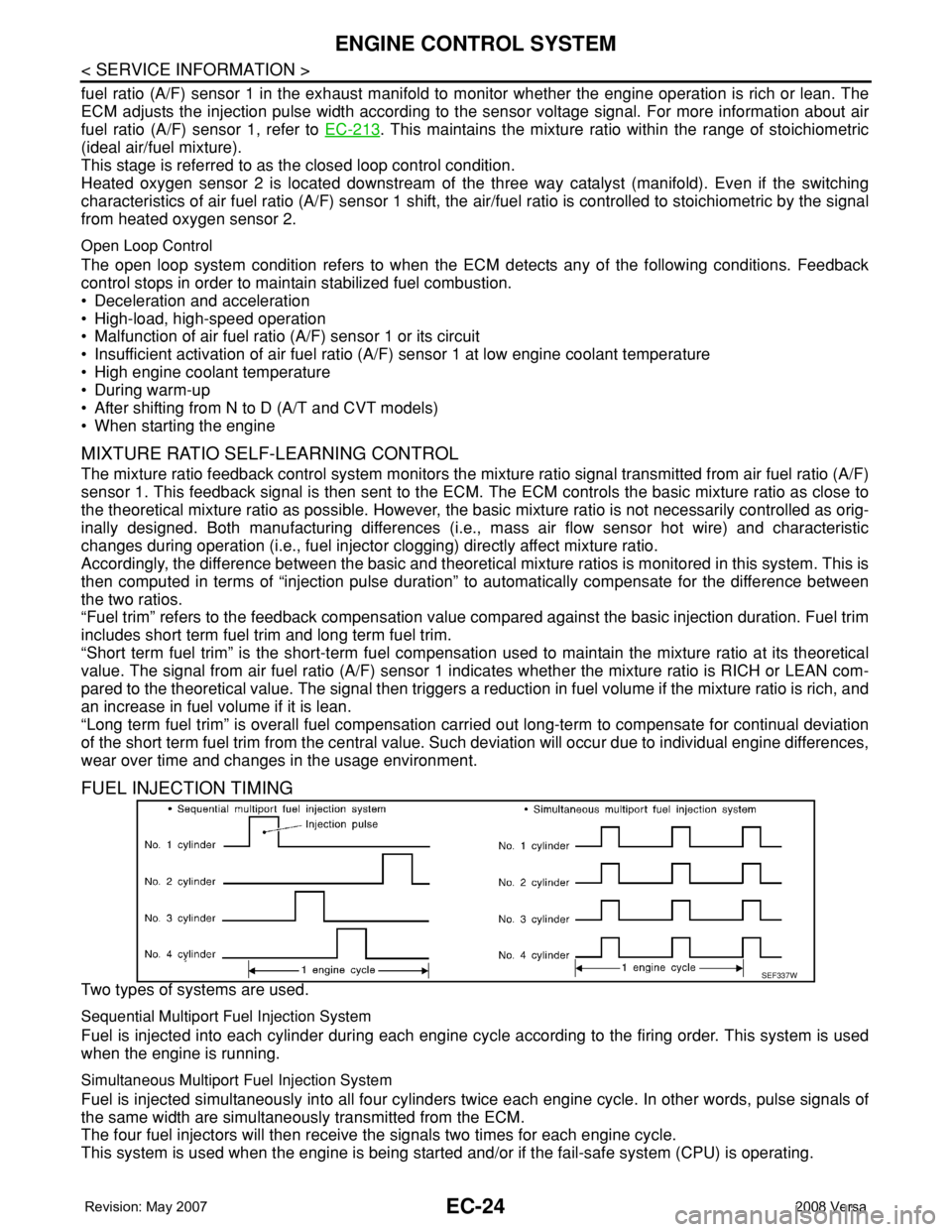
FUEL INJECTION TIMING
Two types of systems are used.
Sequential Multiport Fuel Injection System
Fuel is injected into each cylinder during each engine cycle according to the firing order. This system is used
when the engine is running.
Simultaneous Multiport Fuel Injection System
Fuel is injected simultaneously into all four cylinders twice each engine cycle. In other words, pulse signals of
the same width are simultaneously transmitted from the ECM.
The four fuel injectors will then receive the signals two times for each engine cycle.
This system is used when the engine is being started and/or if the fail-safe system (CPU) is operating.
SEF337W
Page 1336 of 2771
EC-262
< SERVICE INFORMATION >
DTC P0171 FUEL INJECTION SYSTEM FUNCTION
1. Install all removed parts.
2. Start engine and warm it up to normal operating temperature.
3. Check mass air flow sensor signal in Service $01 with GST.
OK or NG
OK >> GO TO 7.
NG >> Check connectors for rusted terminals or loose connections in the mass air flow sensor circuit or
ground. Refer to EC-167
.
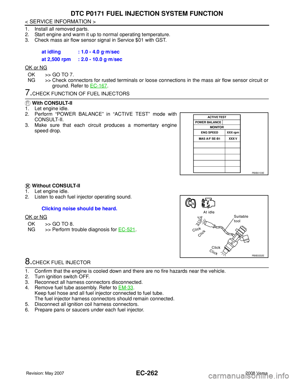
7.CHECK FUNCTION OF FUEL INJECTORS
With CONSULT-II
1. Let engine idle.
2. Perform “POWER BALANCE” in “ACTIVE TEST” mode with
CONSULT-II.
3. Make sure that each circuit produces a momentary engine
speed drop.
Without CONSULT-II
1. Let engine idle.
2. Listen to each fuel injector operating sound.
OK or NG
OK >> GO TO 8.
NG >> Perform trouble diagnosis for EC-521
.
8.CHECK FUEL INJECTOR
1. Confirm that the engine is cooled down and there are no fire hazards near the vehicle.
2. Turn ignition switch OFF.
3. Reconnect all harness connectors disconnected.
4. Remove fuel tube assembly. Refer to EM-33
.
Keep fuel hose and all fuel injector connected to fuel tube.
The fuel injector harness connectors should remain connected.
5. Disconnect all ignition coil harness connectors.
6. Prepare pans or saucers under each fuel injector.at idling : 1.0 - 4.0 g·m/sec
at 2,500 rpm : 2.0 - 10.0 g·m/sec
PBIB0133E
Clicking noise should be heard.
PBIB3332E
Page 1337 of 2771
DTC P0171 FUEL INJECTION SYSTEM FUNCTION
EC-263
< SERVICE INFORMATION >
C
D
E
F
G
H
I
J
K
L
MA
EC
N
P O
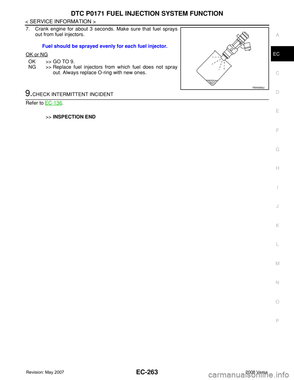
7. Crank engine for about 3 seconds. Make sure that fuel sprays
out from fuel injectors.
OK or NG
OK >> GO TO 9.
NG >> Replace fuel injectors from which fuel does not spray
out. Always replace O-ring with new ones.
9.CHECK INTERMITTENT INCIDENT
Refer to EC-136
.
>>INSPECTION END Fuel should be sprayed evenly for each fuel injector.
PBIA9666J
Page 1343 of 2771
DTC P0172 FUEL INJECTION SYSTEM FUNCTION
EC-269
< SERVICE INFORMATION >
C
D
E
F
G
H
I
J
K
L
MA
EC
N
P OOK or NG
OK >> GO TO 7.
NG >> Check connectors for rusted terminals or loose connections in the mass air flow sensor circuit or
ground. Refer to EC-167
.
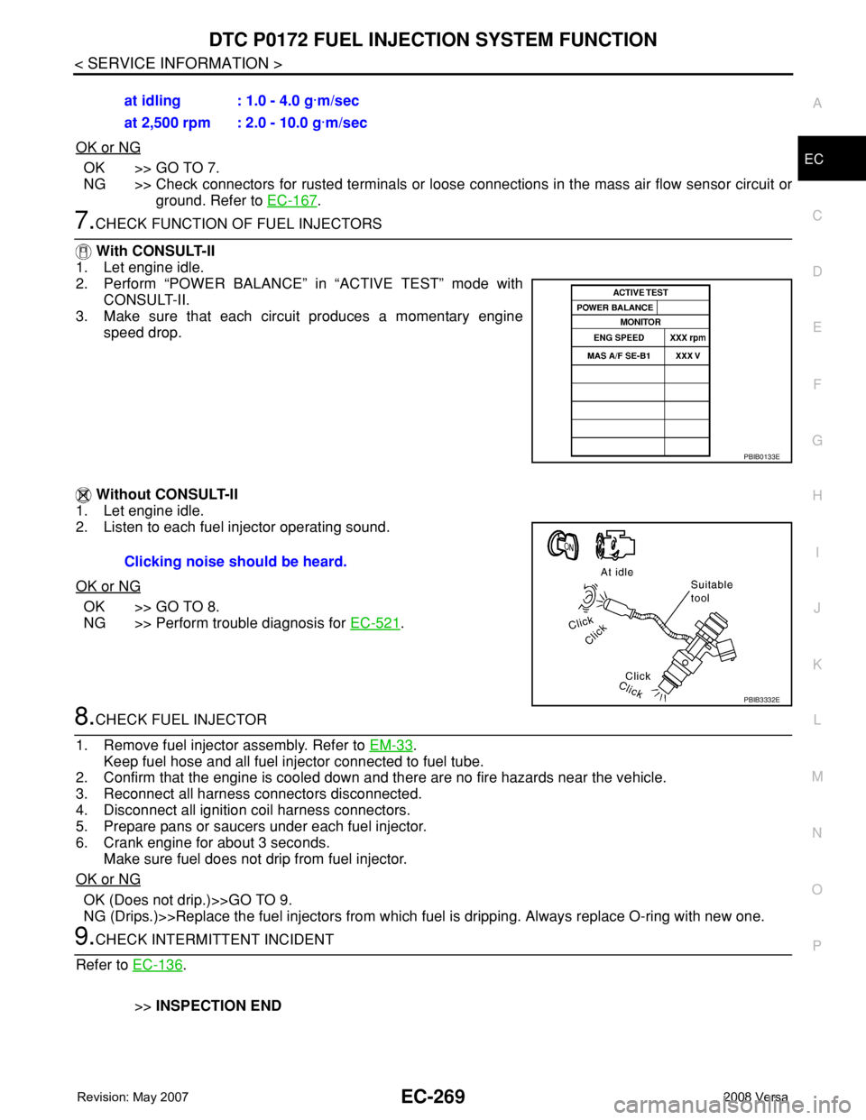
7.CHECK FUNCTION OF FUEL INJECTORS
With CONSULT-II
1. Let engine idle.
2. Perform “POWER BALANCE” in “ACTIVE TEST” mode with
CONSULT-II.
3. Make sure that each circuit produces a momentary engine
speed drop.
Without CONSULT-II
1. Let engine idle.
2. Listen to each fuel injector operating sound.
OK or NG
OK >> GO TO 8.
NG >> Perform trouble diagnosis for EC-521
.
8.CHECK FUEL INJECTOR
1. Remove fuel injector assembly. Refer to EM-33
.
Keep fuel hose and all fuel injector connected to fuel tube.
2. Confirm that the engine is cooled down and there are no fire hazards near the vehicle.
3. Reconnect all harness connectors disconnected.
4. Disconnect all ignition coil harness connectors.
5. Prepare pans or saucers under each fuel injector.
6. Crank engine for about 3 seconds.
Make sure fuel does not drip from fuel injector.
OK or NG
OK (Does not drip.)>>GO TO 9.
NG (Drips.)>>Replace the fuel injectors from which fuel is dripping. Always replace O-ring with new one.
9.CHECK INTERMITTENT INCIDENT
Refer to EC-136
.
>>INSPECTION END at idling : 1.0 - 4.0 g·m/sec
at 2,500 rpm : 2.0 - 10.0 g·m/sec
PBIB0133E
Clicking noise should be heard.
PBIB3332E
Page 1384 of 2771
EC-310
< SERVICE INFORMATION >
DTC P0420 THREE WAY CATALYST FUNCTION
Diagnosis Procedure
INFOID:0000000001702819
1.CHECK EXHAUST SYSTEM
Visually check exhaust tubes and muffler for dent.
OK or NG
OK >> GO TO 2.
NG >> Repair or replace.
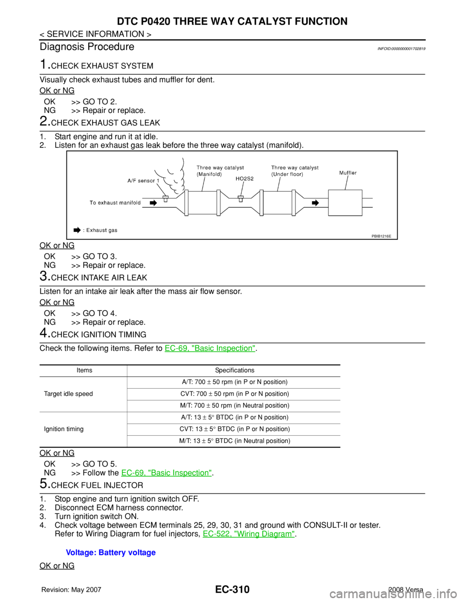
2.CHECK EXHAUST GAS LEAK
1. Start engine and run it at idle.
2. Listen for an exhaust gas leak before the three way catalyst (manifold).
OK or NG
OK >> GO TO 3.
NG >> Repair or replace.
3.CHECK INTAKE AIR LEAK
Listen for an intake air leak after the mass air flow sensor.
OK or NG
OK >> GO TO 4.
NG >> Repair or replace.
4.CHECK IGNITION TIMING
Check the following items. Refer to EC-69, "
Basic Inspection".
OK or NG
OK >> GO TO 5.
NG >> Follow the EC-69, "
Basic Inspection".
5.CHECK FUEL INJECTOR
1. Stop engine and turn ignition switch OFF.
2. Disconnect ECM harness connector.
3. Turn ignition switch ON.
4. Check voltage between ECM terminals 25, 29, 30, 31 and ground with CONSULT-II or tester.
Refer to Wiring Diagram for fuel injectors, EC-522, "
Wiring Diagram".
OK or NG
PBIB1216E
Items Specifications
Target idle speedA/T: 700 ± 50 rpm (in P or N position)
CVT: 700 ± 50 rpm (in P or N position)
M/T: 700 ± 50 rpm (in Neutral position)
Ignition timingA/T: 13 ± 5° BTDC (in P or N position)
CVT: 13 ± 5° BTDC (in P or N position)
M/T: 13 ± 5° BTDC (in Neutral position)
Voltage: Battery voltage
Page 1386 of 2771
EC-312
< SERVICE INFORMATION >
DTC P0420 THREE WAY CATALYST FUNCTION
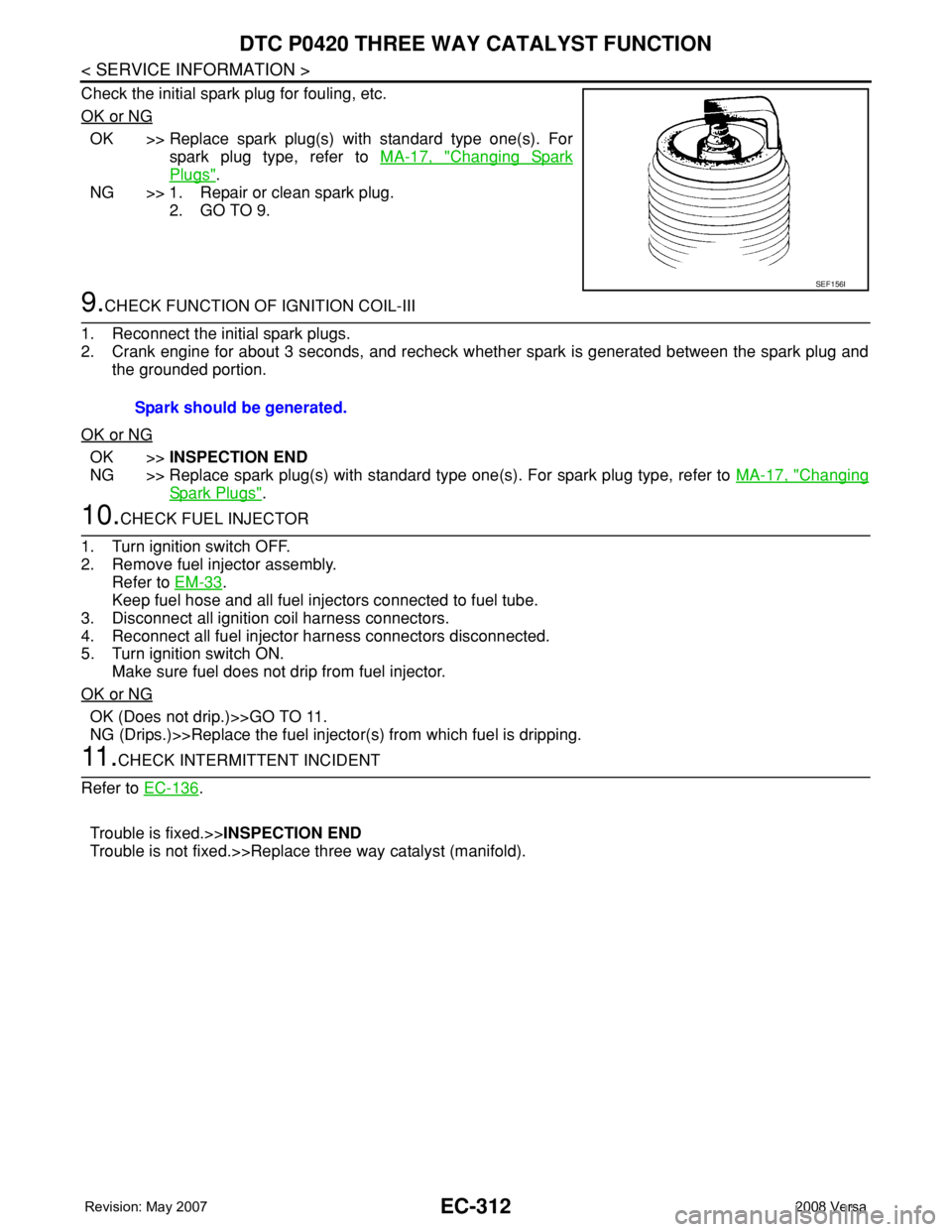
Check the initial spark plug for fouling, etc.
OK or NG
OK >> Replace spark plug(s) with standard type one(s). For
spark plug type, refer to MA-17, "
Changing Spark
Plugs".
NG >> 1. Repair or clean spark plug.
2. GO TO 9.
9.CHECK FUNCTION OF IGNITION COIL-III
1. Reconnect the initial spark plugs.
2. Crank engine for about 3 seconds, and recheck whether spark is generated between the spark plug and
the grounded portion.
OK or NG
OK >>INSPECTION END
NG >> Replace spark plug(s) with standard type one(s). For spark plug type, refer to MA-17, "
Changing
Spark Plugs".
10.CHECK FUEL INJECTOR
1. Turn ignition switch OFF.
2. Remove fuel injector assembly.
Refer to EM-33
.
Keep fuel hose and all fuel injectors connected to fuel tube.
3. Disconnect all ignition coil harness connectors.
4. Reconnect all fuel injector harness connectors disconnected.
5. Turn ignition switch ON.
Make sure fuel does not drip from fuel injector.
OK or NG
OK (Does not drip.)>>GO TO 11.
NG (Drips.)>>Replace the fuel injector(s) from which fuel is dripping.
11 .CHECK INTERMITTENT INCIDENT
Refer to EC-136
.
Trouble is fixed.>>INSPECTION END
Trouble is not fixed.>>Replace three way catalyst (manifold).
SEF156I
Spark should be generated.