2008 NISSAN TIIDA Power window
[x] Cancel search: Power windowPage 634 of 2771
BL-200
< SERVICE INFORMATION >
VEHICLE SECURITY (THEFT WARNING) SYSTEM
*1 : Make sure the system is in the armed phase.
Diagnosis Procedure 1INFOID:0000000001704094
1-1 DOOR SWITCH CHECK (HATCHBACK)
1.CHECK DOOR SWITCHES INPUT SIGNAL
With CONSULT-III
Check door switches ("DOOR SW-DR", "DOOR SW-AS", "DOOR SW-RL", "DOOR SW-RR", "BACK DOOR
SW") in DATA MONITOR mode with CONSULT–III. Refer to BL-36, "
CONSULT-III Function (BCM)".
• When doors are open:
• When doors are closed:
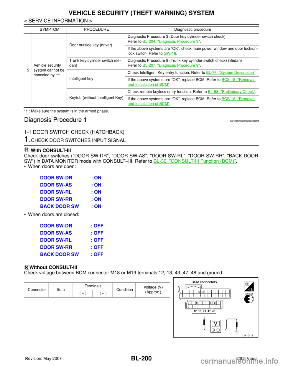
Without CONSULT-III
Check voltage between BCM connector M18 or M19 terminals 12, 13, 43, 47, 48 and ground.
5Vehicle security
system cannot be
canceled by ····Door outside key (driver)Diagnostic Procedure 3 (Door key cylinder switch check).
Refer to BL-204, "
Diagnosis Procedure 3".
If the above systems are “OK”, check main power window and door lock/un-
lock switch. Refer to GW-18
.
Trunk key cylinder switch (se-
dan)Diagnostic Procedure 9 (Trunk key cylinder switch check) (Sedan)
Refer to BL-207, "
Diagnosis Procedure 9".
Intelligent keyCheck Intelligent Key entry function. Refer to BL-76, "
System Description"
If the above systems are “OK”, replace BCM. Refer to BCS-18, "Removal
and Installation of BCM".
Keyfob (without Intelligent Key)Check remote keyless entry function. Refer to BL-58, "
Preliminary Check".
If the above systems are “OK”, replace BCM. Refer to BCS-18, "
Removal
and Installation of BCM". SYMPTOM PROCEDURE Diagnostic procedure
DOOR SW-DR : ON
DOOR SW-AS : ON
DOOR SW-RL : ON
DOOR SW-RR : ON
BACK DOOR SW : ON
DOOR SW-DR : OFF
DOOR SW-AS : OFF
DOOR SW-RL : OFF
DOOR SW-RR : OFF
BACK DOOR SW : OFF
Connector ItemTe r m i n a l s
ConditionVoltage (V)
(Approx.)
( + ) ( – )
LIIA1041E
Page 1188 of 2771
![NISSAN TIIDA 2008 Service Repair Manual EC-114
< SERVICE INFORMATION >
TROUBLE DIAGNOSIS
FUEL T/TMP SE [°C]
or [°F]ו The fuel temperature (determined by the signal
voltage of the fuel tank temperature sensor) is
displayed.
INT/A TE NISSAN TIIDA 2008 Service Repair Manual EC-114
< SERVICE INFORMATION >
TROUBLE DIAGNOSIS
FUEL T/TMP SE [°C]
or [°F]ו The fuel temperature (determined by the signal
voltage of the fuel tank temperature sensor) is
displayed.
INT/A TE](/manual-img/5/57399/w960_57399-1187.png)
EC-114
< SERVICE INFORMATION >
TROUBLE DIAGNOSIS
FUEL T/TMP SE [°C]
or [°F]ו The fuel temperature (determined by the signal
voltage of the fuel tank temperature sensor) is
displayed.
INT/A TEMP SE
[°C] or [°F]×ו The intake air temperature (determined by the
signal voltage of the intake air temperature
sensor) is indicated.
EVAP SYS PRES [V]ו The signal voltage of EVAP control system
pressure sensor is displayed.
FUEL LEVEL SE [V]ו The signal voltage of the fuel level sensor is
displayed.
START SIGNAL
[ON/OFF]×ו Indicates start signal status [ON/OFF] comput-
ed by the ECM according to the signals of en-
gine speed and battery voltage.• After starting the engine, [OFF] is
displayed regardless of the starter
signal.
CLSD THL POS
[ON/OFF]×ו Indicates idle position [ON/OFF] computed by
the ECM according to the accelerator pedal po-
sition sensor signal.
AIR COND SIG
[ON/OFF]×ו Indicates [ON/OFF] condition of the air condi-
tioner switch as determined by the air condi-
tioner signal.
P/N POSI SW
[ON/OFF]×ו Indicates [ON/OFF] condition from the park/
neutral position (PNP) switch signal.
PW/ST SIGNAL [ON/
OFF]×ו [ON/OFF] condition of the power steering sys-
tem (determined by the signal sent from EPS
control unit) is indicated.
LOAD SIGNAL
[ON/OFF]×ו Indicates [ON/OFF] condition from the electri-
cal load signal.
ON: Rear window defogger switch is ON and/
or lighting switch is in 2nd position.
OFF: Both rear window defogger switch and
lighting switch are OFF.
IGNITION SW
[ON/OFF]ו Indicates [ON/OFF] condition from ignition
switch.
HEATER FAN SW
[ON/OFF]ו Indicates [ON/OFF] condition from the heater
fan switch signal.
BRAKE SW
[ON/OFF]ו Indicates [ON/OFF] condition from the stop
lamp switch signal.
INJ PULSE-B1
[msec]ו Indicates the actual fuel injection pulse width
compensated by ECM according to the input
signals.• When the engine is stopped, a
certain computed value is indicat-
ed.
IGN TIMING [BTDC]• Indicates the ignition timing computed by ECM
according to the input signals.• When the engine is stopped, a
certain value is indicated.
CAL/LD VALUE [%]• “Calculated load value” indicates the value of
the current airflow divided by peak airflow.
MASS AIRFLOW
[g·m/s]• Indicates the mass airflow computed by ECM
according to the signal voltage of the mass air
flow sensor.
PURG VOL C/V [%]• Indicates the EVAP canister purge volume con-
trol solenoid valve control value computed by
the ECM according to the input signals.
• The opening becomes larger as the value in-
creases.
INT/V TIM (B1) [°CA]• Indicates [°CA] of intake camshaft advanced
angle. Monitored item [Unit]ECM IN-
PUT SIG-
NALSMAIN
SIG-
NALSDescription Remarks
Page 1655 of 2771
EI-32
< ON-VEHICLE REPAIR >
DOOR FINISHER
DOOR FINISHER
Removal and InstallationINFOID:0000000001704233
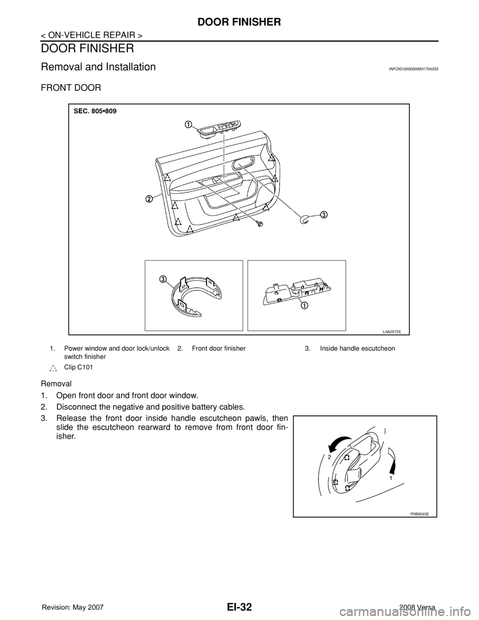
FRONT DOOR
Removal
1. Open front door and front door window.
2. Disconnect the negative and positive battery cables.
3. Release the front door inside handle escutcheon pawls, then
slide the escutcheon rearward to remove from front door fin-
isher.
1. Power window and door lock/unlock
switch finisher2. Front door finisher 3. Inside handle escutcheon
Clip C101
LIIA2572E
PIIB6040E
Page 1656 of 2771
DOOR FINISHER
EI-33
< ON-VEHICLE REPAIR >
C
D
E
F
G
H
J
K
L
MA
B
EI
N
O
P
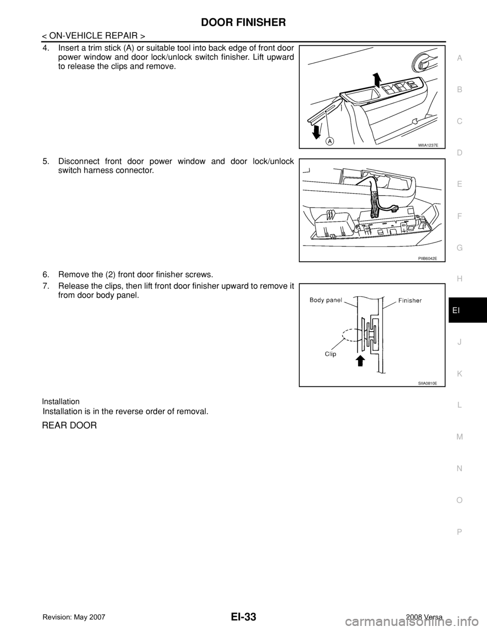
4. Insert a trim stick (A) or suitable tool into back edge of front door
power window and door lock/unlock switch finisher. Lift upward
to release the clips and remove.
5. Disconnect front door power window and door lock/unlock
switch harness connector.
6. Remove the (2) front door finisher screws.
7. Release the clips, then lift front door finisher upward to remove it
from door body panel.
Installation
Installation is in the reverse order of removal.
REAR DOOR
WIIA1237E
PIIB6042E
SIIA0810E
Page 1657 of 2771
EI-34
< ON-VEHICLE REPAIR >
DOOR FINISHER
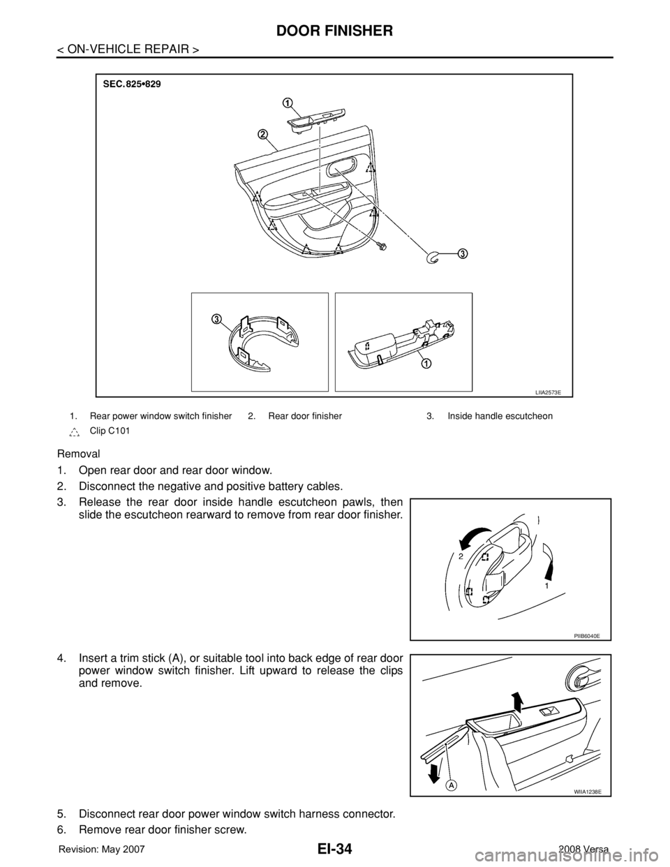
Removal
1. Open rear door and rear door window.
2. Disconnect the negative and positive battery cables.
3. Release the rear door inside handle escutcheon pawls, then
slide the escutcheon rearward to remove from rear door finisher.
4. Insert a trim stick (A), or suitable tool into back edge of rear door
power window switch finisher. Lift upward to release the clips
and remove.
5. Disconnect rear door power window switch harness connector.
6. Remove rear door finisher screw.
1. Rear power window switch finisher 2. Rear door finisher 3. Inside handle escutcheon
Clip C101
LIIA2573E
PIIB6040E
WIIA1238E
Page 1902 of 2771
GW-1
BODY
C
D
E
F
G
H
J
K
L
M
SECTION GW
A
B
GW
N
O
P
CONTENTS
GLASSES, WINDOW SYSTEM & MIRRORS
SERVICE INFORMATION ............................3
PRECAUTIONS ...................................................3
Precaution for Supplemental Restraint System
(SRS) "AIR BAG" and "SEAT BELT PRE-TEN-
SIONER" ...................................................................
3
Precaution for Procedure without Cowl Top Cover ......3
Handling for Adhesive and Primer ............................3
PREPARATION ...................................................4
Commercial Service Tool ..........................................4
SQUEAK AND RATTLE TROUBLE DIAG-
NOSES ................................................................
5
Work Flow .................................................................5
Generic Squeak and Rattle Troubleshooting ............7
Diagnostic Worksheet ...............................................9
WINDSHIELD GLASS ........................................11
Removal and Installation .........................................11
OPERA WINDOW GLASS .................................13
Removal and Installation .........................................13
REAR WINDOW GLASS AND MOLDING .........15
Removal and Installation .........................................15
POWER WINDOW SYSTEM ..............................18
Component Parts and Harness Connector Loca-
tion ..........................................................................
18
System Description .................................................18
CAN Communication System Description ...............22
Schematic ...............................................................22
Wiring Diagram - WINDOW- ...................................23
Main Power Window and Door Lock/Unlock
Switch Harness Connector Terminal Layout ...........
26
Terminal and Reference Value for Main Power
Window and Door Lock/Unlock Switch ...................
27
Terminal and Reference Value for BCM .................28
Work Flow ...............................................................28
CONSULT-III Function (BCM) .................................28
Power Window Auto Operation Initialization ...........29
Trouble Diagnosis Symptom Chart ..........................29
BCM Power Supply and Ground Circuit Inspection
....
30
Main Power Window and Door Lock/Unlock
Switch Power Supply and Ground Circuit Inspec-
tion ...........................................................................
30
Front Power Window Motor LH Circuit Inspection ....31
Front Power Window RH Circuit Inspection (Pow-
er Window and Door Lock/Unlock Switch RH Op-
eration) ....................................................................
32
Front Power Window Motor RH Circuit Inspection ....32
Encoder Circuit Inspection .......................................34
Door Switch Check ..................................................36
Rear Power Window LH Circuit Inspection (Rear
Power Window Switch LH Operation) .....................
37
Rear Power Window RH Circuit Inspection (Rear
Power Window Switch RH Operation) .....................
38
Rear Power Window Motor LH Circuit Inspection ....38
Rear Power Window Motor RH Circuit Inspection ....40
FRONT DOOR GLASS AND REGULATOR .....42
Removal and Installation .........................................42
Disassembly and Assembly .....................................44
Inspection after Installation ......................................44
REAR DOOR GLASS AND REGULATOR .......46
Removal and Installation .........................................46
Disassembly and Assembly .....................................48
Inspection after Installation ......................................48
REAR WINDOW DEFOGGER ..........................49
Component Parts and Harness Connector Loca-
tion ...........................................................................
49
System Description ..................................................49
CAN Communication System Description ...............50
Wiring Diagram - DEF - ...........................................51
Terminal and Reference Value for BCM ..................52
Terminal and Reference Value for IPDM E/R ..........52
Work Flow ................................................................53
CONSULT-III Function (BCM) .................................53
Trouble Diagnosis Symptom Chart ..........................53
Page 1903 of 2771

GW-2
BCM Power Supply and Ground Circuit Inspection
...
54
Rear Window Defogger Switch Circuit Inspection ...54
Rear Window Defogger Circuit Inspection ..............55
Door Mirror Defogger Circuit Inspection .................58
Filament Check .......................................................59
Filament Repair ......................................................60
DOOR MIRROR .................................................62
Wiring Diagram - MIRROR - ...................................62
Removal and Installation .........................................63
Disassembly and Assembly ....................................63
INSIDE MIRROR ................................................65
Removal and Installation .........................................65
Page 1913 of 2771
GW-12
< SERVICE INFORMATION >
WINDSHIELD GLASS
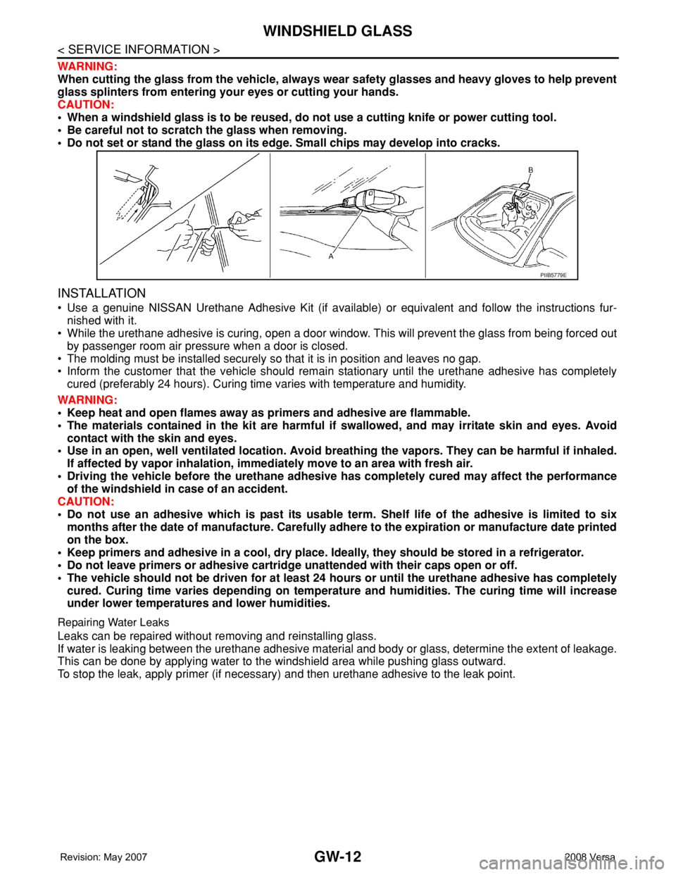
WARNING:
When cutting the glass from the vehicle, always wear safety glasses and heavy gloves to help prevent
glass splinters from entering your eyes or cutting your hands.
CAUTION:
• When a windshield glass is to be reused, do not use a cutting knife or power cutting tool.
• Be careful not to scratch the glass when removing.
• Do not set or stand the glass on its edge. Small chips may develop into cracks.
INSTALLATION
• Use a genuine NISSAN Urethane Adhesive Kit (if available) or equivalent and follow the instructions fur-
nished with it.
• While the urethane adhesive is curing, open a door window. This will prevent the glass from being forced out
by passenger room air pressure when a door is closed.
• The molding must be installed securely so that it is in position and leaves no gap.
• Inform the customer that the vehicle should remain stationary until the urethane adhesive has completely
cured (preferably 24 hours). Curing time varies with temperature and humidity.
WARNING:
• Keep heat and open flames away as primers and adhesive are flammable.
• The materials contained in the kit are harmful if swallowed, and may irritate skin and eyes. Avoid
contact with the skin and eyes.
• Use in an open, well ventilated location. Avoid breathing the vapors. They can be harmful if inhaled.
If affected by vapor inhalation, immediately move to an area with fresh air.
• Driving the vehicle before the urethane adhesive has completely cured may affect the performance
of the windshield in case of an accident.
CAUTION:
• Do not use an adhesive which is past its usable term. Shelf life of the adhesive is limited to six
months after the date of manufacture. Carefully adhere to the expiration or manufacture date printed
on the box.
• Keep primers and adhesive in a cool, dry place. Ideally, they should be stored in a refrigerator.
• Do not leave primers or adhesive cartridge unattended with their caps open or off.
• The vehicle should not be driven for at least 24 hours or until the urethane adhesive has completely
cured. Curing time varies depending on temperature and humidities. The curing time will increase
under lower temperatures and lower humidities.
Repairing Water Leaks
Leaks can be repaired without removing and reinstalling glass.
If water is leaking between the urethane adhesive material and body or glass, determine the extent of leakage.
This can be done by applying water to the windshield area while pushing glass outward.
To stop the leak, apply primer (if necessary) and then urethane adhesive to the leak point.
PIIB5779E