2008 NISSAN TIIDA Power window
[x] Cancel search: Power windowPage 1914 of 2771
OPERA WINDOW GLASS
GW-13
< SERVICE INFORMATION >
C
D
E
F
G
H
J
K
L
MA
B
GW
N
O
P
OPERA WINDOW GLASS
Removal and InstallationINFOID:0000000001704136
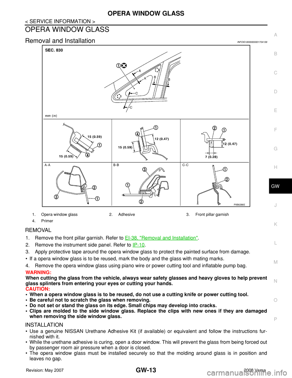
REMOVAL
1. Remove the front pillar garnish. Refer to EI-38, "Removal and Installation".
2. Remove the instrument side panel. Refer to IP-10
.
3. Apply protective tape around the opera window glass to protect the painted surface from damage.
• If a opera window glass is to be reused, mark the body and the glass with mating marks.
4. Remove the opera window glass using piano wire or power cutting tool and inflatable pump bag.
WARNING:
When cutting the glass from the vehicle, always wear safety glasses and heavy gloves to help prevent
glass splinters from entering your eyes or cutting your hands.
CAUTION:
• When a opera window glass is to be reused, do not use a cutting knife or power cutting tool.
• Be careful not to scratch the glass when removing.
• Do not set or stand the glass on its edge. Small chips may develop into cracks.
• Clips are molded to the side window glass. Replace the clips with new ones if they are damaged
when removing the side window glass.
INSTALLATION
• Use a genuine NISSAN Urethane Adhesive Kit (if available) or equivalent and follow the instructions fur-
nished with it.
• While the urethane adhesive is curing, open a door window. This will prevent the glass from being forced out
by passenger room air pressure when a door is closed.
• The opera window glass must be installed securely so that the molding around glass is in position and
leaves no gap.
PIIB6286E
1. Opera window glass 2. Adhesive 3. Front pillar garnish
4. Primer
Page 1917 of 2771
GW-16
< SERVICE INFORMATION >
REAR WINDOW GLASS AND MOLDING
Sedan
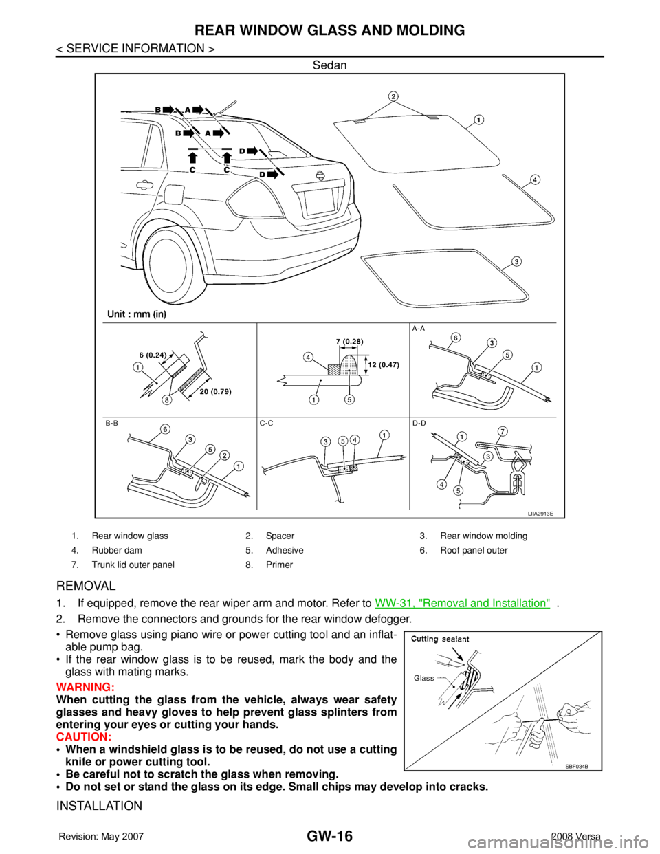
REMOVAL
1. If equipped, remove the rear wiper arm and motor. Refer to WW-31, "Removal and Installation" .
2. Remove the connectors and grounds for the rear window defogger.
• Remove glass using piano wire or power cutting tool and an inflat-
able pump bag.
• If the rear window glass is to be reused, mark the body and the
glass with mating marks.
WARNING:
When cutting the glass from the vehicle, always wear safety
glasses and heavy gloves to help prevent glass splinters from
entering your eyes or cutting your hands.
CAUTION:
• When a windshield glass is to be reused, do not use a cutting
knife or power cutting tool.
• Be careful not to scratch the glass when removing.
• Do not set or stand the glass on its edge. Small chips may develop into cracks.
INSTALLATION
LIIA2913E
1. Rear window glass 2. Spacer 3. Rear window molding
4. Rubber dam 5. Adhesive 6. Roof panel outer
7. Trunk lid outer panel 8. Primer
SBF034B
Page 1919 of 2771
GW-18
< SERVICE INFORMATION >
POWER WINDOW SYSTEM
POWER WINDOW SYSTEM
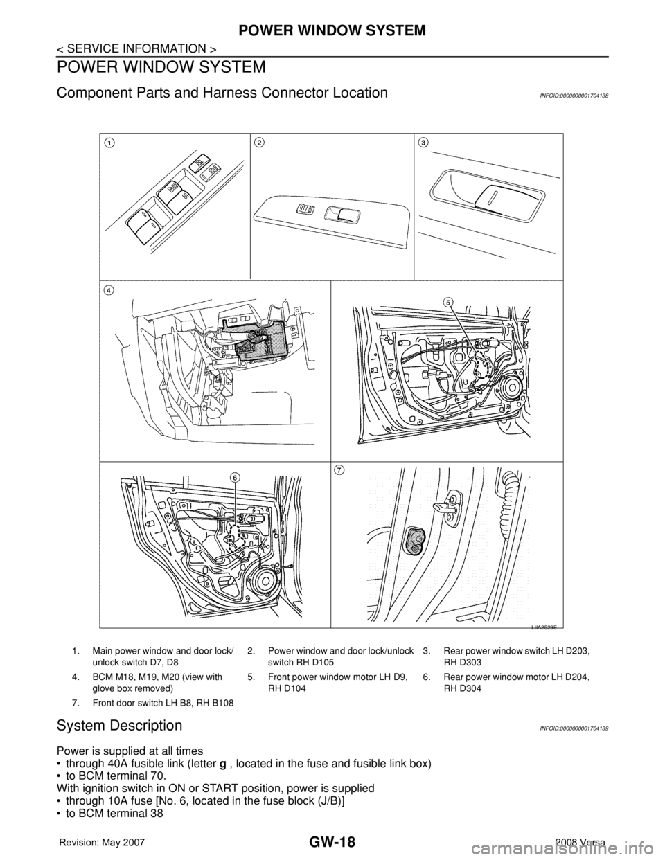
Component Parts and Harness Connector LocationINFOID:0000000001704138
System DescriptionINFOID:0000000001704139
Power is supplied at all times
• through 40A fusible link (letter g , located in the fuse and fusible link box)
• to BCM terminal 70.
With ignition switch in ON or START position, power is supplied
• through 10A fuse [No. 6, located in the fuse block (J/B)]
• to BCM terminal 38
1. Main power window and door lock/
unlock switch D7, D82. Power window and door lock/unlock
switch RH D1053. Rear power window switch LH D203,
RH D303
4. BCM M18, M19, M20 (view with
glove box removed)5. Front power window motor LH D9,
RH D1046. Rear power window motor LH D204,
RH D304
7. Front door switch LH B8, RH B108
LIIA2529E
Page 1920 of 2771

POWER WINDOW SYSTEM
GW-19
< SERVICE INFORMATION >
C
D
E
F
G
H
J
K
L
MA
B
GW
N
O
P
• through BCM terminal 68
• to main power window and door lock/unlock switch terminal 10
• to power window and door lock/unlock switch RH terminal 8 and
• to rear power window switches LH and RH terminal 1.
Ground is supplied
• to BCM terminal 67
• to main power window and door lock/unlock switch terminal 17 and
• to power window and door lock/unlock switch RH terminal 3
• through body grounds M57 and M61.
With ignition switch in ACC or ON position, power is supplied
• through 10A fuse [No. 20, located in the fuse block (J/B)]
• to BCM terminal 11.
MANUAL OPERATION
Front Door LH
WINDOW UP
When the front LH switch in the main power window and door lock/unlock switch is pulled in the up position,
power is supplied
• through main power window and door lock/unlock switch terminal 8
• to front power window motor LH terminal 2.
Ground is supplied
• through main power window and door lock/unlock switch terminal 11
• to front power window motor LH terminal 3.
Then, the motor raises the window until the switch is released.
WINDOW DOWN
When the front LH switch in the main power window and door lock/unlock switch is pressed in the down posi-
tion, power is supplied
• through main power window and door lock/unlock switch terminal 11
• to front power window motor LH terminal 3.
Ground is supplied
• through main power window and door lock/unlock switch terminal 8
• to front power window motor LH terminal 2.
Then, the motor lowers the window until the switch is released.
Front Door RH
POWER WINDOW AND DOOR LOCK/UNLOCK SWITCH RH OPERATION
WINDOW UP
When the power window and door lock/unlock switch RH is pulled in the up position, power is supplied
• through power window and door lock/unlock switch RH terminal 7
• to front power window motor RH terminal 2.
Ground is supplied
• through power window and door lock/unlock switch RH terminal 6
• to front power window motor RH terminal 1.
Then, the motor raises the window until the switch is released.
WINDOW DOWN
When the power window and door lock/unlock switch RH is pressed in the down position, power is supplied
• through power window and door lock/unlock switch RH terminal 6
• to front power window motor RH terminal 1.
Ground is supplied
• through power window and door lock/unlock switch RH terminal 7
• to front power window motor RH terminal 2.
Then, the motor lowers the window until the switch is released.
MAIN POWER WINDOW AND DOOR LOCK/UNLOCK SWITCH OPERATION
WINDOW UP
When the main power window and door lock/unlock switch (front RH) is pulled in the up position, power is sup-
plied
• through main power window and door lock/unlock switch terminal 16
• to power window and door lock/unlock switch RH terminal 12
• through power window and door lock/unlock switch RH terminal 7
• to front power window motor RH terminal 2.
Ground is supplied
Page 1921 of 2771

GW-20
< SERVICE INFORMATION >
POWER WINDOW SYSTEM
• through main power window and door lock/unlock switch terminal 12
• to power window and door lock/unlock switch RH terminal 11
• through power window and door lock/unlock switch LH terminal 6
• to front power window motor RH terminal 1.
Then, the motor raises the window until the switch is released.
WINDOW DOWN
When the main power window and door lock/unlock switch (front RH) is pressed in the down position, power is
supplied
• through main power window and door lock/unlock switch terminal 12
• to power window and door lock/unlock switch LH terminal 11
• through power window and door lock/unlock switch LH terminal 6
• to front power window motor RH terminal 1.
Ground is supplied
• through main power window and door lock/unlock switch terminal 16
• to power window and door lock/unlock switch RH terminal 12
• through power window and door lock/unlock switch LH terminal 7
• to front power window motor RH terminal 2.
Then, the motor lowers the window until the switch is released.
Rear Door (LH or RH)
REAR POWER WINDOW SWITCH LH OR RH OPERATION
WINDOW UP
When the rear power window switch LH or RH is pulled in the up position, power is supplied
• through rear power window switch LH or RH terminal 5
• to rear power window motor LH or RH terminal 2.
Ground is supplied
• through rear power window switch LH or RH terminal 4
• to rear power window motor LH or RH terminal 1.
Then, the motor raises the window until the switch is released.
WINDOW DOWN
When the rear power window switch LH or RH is pressed in the down position, power is supplied
• through rear power window switch LH or RH terminal 4
• to rear power window motor LH or RH terminal 1.
Ground is supplied
• through rear power window switch LH or RH terminal 5
• to rear power window motor LH or RH terminal 2.
Then, the motor lowers the window until the switch is released.
MAIN POWER WINDOW AND DOOR LOCK/UNLOCK SWITCH OPERATION
WINDOW UP
When the main power window and door lock/unlock switch (rear LH) is pulled in the up position, power is sup-
plied
• through main power window and door lock/unlock switch terminal 1
• to rear power window switch LH terminal 2
• through rear power window switch LH terminal 5
• to rear power window motor LH terminal 2.
Ground is supplied
• through main power window and door lock/unlock switch terminal 3
• to rear power window switch LH terminal 3
• through rear power window switch LH terminal 4
• to rear power window motor LH terminal 1.
Then, the motor raises the window until the switch is released.
When the main power window and door lock/unlock switch (rear RH) is pulled in the up position, power is sup-
plied
• through main power window and door lock/unlock switch terminal 7
• to rear power window switch RH terminal 2
• through rear power window switch RH terminal 5
• to rear power window motor RH terminal 2.
Ground is supplied
• through main power window and door lock/unlock switch terminal 5
• through rear power window switch RH terminal 3
• to rear power window switch RH terminal 4
• to rear power window motor RH terminal 1.
Page 1922 of 2771
POWER WINDOW SYSTEM
GW-21
< SERVICE INFORMATION >
C
D
E
F
G
H
J
K
L
MA
B
GW
N
O
P
Then, the motor raises the window until the switch is released.
WINDOW DOWN
When the main power window and door lock/unlock switch (rear LH) is pressed in the down position, power is
supplied
• through main power window and door lock/unlock switch terminal 3
• to rear power window switch LH terminal 3
• through rear power window switch LH terminal 4
• to rear power window motor LH terminal 1.
Ground is supplied
• through main power window and door lock/unlock switch terminal 1
• to rear power window switch LH terminal 2
• through rear power window switch LH terminal 5
• to rear power window motor LH terminal 2.
Then, the motor lowers the window until the switch is released.
When the main power window and door lock/unlock switch (rear RH) is pressed in the down position, power is
supplied
• through main power window and door lock/unlock switch terminal 5
• to rear power window switch RH terminal 3
• through rear power window switch RH terminal 4
• to rear power window motor RH terminal 1.
Ground is supplied
• through main power window and door lock/unlock switch terminal 7
• to rear power window switch RH terminal 2
• through rear power window switch RH terminal 5
• to rear power window motor RH terminal 2.
Then, the motor lowers the window until the switch is released.
AUTO OPERATION
The power window AUTO feature enables the driver to open the window without holding the window switch in
the down position.
POWER WINDOW LOCK
The power window lock is designed to lock operation of all windows except for front door window LH.
When in the lock position, the power window lock disables power window and door lock/unlock switch RH and
rear power window switch LH and RH by disconnecting switch ground signal. This prevents the power window
motors from operating.
RETAINED POWER OPERATION
When the ignition switch is turned to the OFF position from ON or START position, power is supplied for 45
seconds
• through BCM terminal 68
• to main power window and door lock/unlock switch terminal 10
• to power window and door lock/unlock switch RH terminal 8 and
• to rear power window switches LH and RH terminal 1.
When power and ground are supplied, the BCM continues to be energized, and the power window can be
operated.
The retained power operation is canceled when the front LH or front RH door is opened.
Retained power operation period can be changed by CONSULT-III. Refer to GW-28, "
CONSULT-III Function
(BCM)" .
ANTI-PINCH SYSTEM
Main power window and door lock/unlock switch monitors the power window motor operation and the power
window position (full closed or other) for front LH power window by the signal from encoder in front power win-
dow motor LH.
When main power window and door lock/unlock switch detects interruption during the following close opera-
tions
• automatic close operation when ignition switch is in the ON position
• automatic close operation during retained power operation
Main power window and door lock/unlock switch controls front power window motor LH for open and the
power window will be lowered.
Page 1923 of 2771
GW-22
< SERVICE INFORMATION >
POWER WINDOW SYSTEM
CAN Communication System Description
INFOID:0000000001704140
Refer to LAN-6, "System Description".
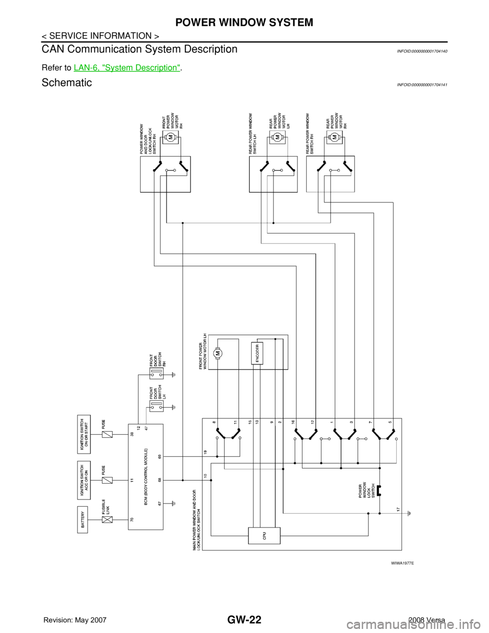
SchematicINFOID:0000000001704141
WIWA1977E
Page 1924 of 2771
POWER WINDOW SYSTEM
GW-23
< SERVICE INFORMATION >
C
D
E
F
G
H
J
K
L
MA
B
GW
N
O
P
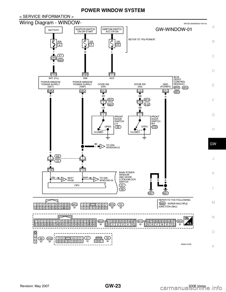
Wiring Diagram - WINDOW-INFOID:0000000001704142
WIWA1978E