Page 2323 of 2771
INPUT SHAFT AND GEARS
MT-35
< SERVICE INFORMATION >
D
E
F
G
H
I
J
K
L
MA
B
MT
N
O
P
INPUT SHAFT AND GEARS
Disassembly and AssemblyINFOID:0000000001703143
GENERAL PRECAUTIONS
• Do not reuse snap ring.
• Position input shaft on the vise with back plate and remove gears and snap rings.
• For installation and removal of snap ring, position snap ring pliers
and flat pliers at both sides of snap ring. Stretch snap ring, and
move it with flat pliers.
• Disassemble gear components putting matching marks on the
parts that do not affect any functions.
DISASSEMBLY
1. Remove snap ring (1).
2. Install the suitable tool (A) onto input shaft rear bearing (1), and
remove input shaft rear bearing (1) from input shaft.
3. Remove washer (1), 6th input gear (2) and 5th-6th synchronizer
assembly (3).
4. Remove needle bearing.
SCIA1755J
PCIB1756E
PCIB1755E
PCIB1750E
Page 2324 of 2771
MT-36
< SERVICE INFORMATION >
INPUT SHAFT AND GEARS
5. Remove snap ring (1), washer and 5th input gear (2).
6. Remove washer.
7. Remove snap ring (1), washer, 4th input gear (2) and 3rd-4th
synchronizer assembly (3).
8. Remove snap ring (1), washer and 3rd input gear (2).
9. Remove input shaft front bearing (1) from input shaft using suit-
able tool.
INSPECTION AFTER DISASSEMBLY
Input Shaft and Gears
PCIB1754E
PCIB1753E
PCIB1752E
PCIB1751E
Page 2325 of 2771
INPUT SHAFT AND GEARS
MT-37
< SERVICE INFORMATION >
D
E
F
G
H
I
J
K
L
MA
B
MT
N
O
P
Check items below. If necessary, replace them with new ones.
• Damage, peeling, dent, uneven wear, bending, and other non-
standard conditions of the shaft.
• Excessive wear, damage, peeling, and other non-standard condi-
tions of the gears.
Synchronizer
Check items below. If necessary, replace them with new ones.
• Damage and excessive wear of contact surfaces of coupling
sleeve, synchronizer hub and insert key.
• Coupling sleeve and synchronizer hub must move smoothly.
• If any crack, damage, or excessive wear is found on cam face of
baulk ring or working face of insert, replace it.
Bearing
Check for damage and rough rotation of bearing. If necessary,
replace with new one.
ASSEMBLY
Assembly is in the reverse order of disassembly.
SCIA7736E
SCIA1753J
SCIA0608J
MTF0041D
Page 2326 of 2771
MT-38
< SERVICE INFORMATION >
INPUT SHAFT AND GEARS
• Press-fit the input shaft front bearing (1) onto the input shaft using
suitable tool (A).
• Press-fit the input shaft rear bearing (1) onto the input shaft using
suitable tool (A), and Tool (B).
CAUTION:
• Do not reuse snap ring.
• Make sure that snap ring is securely installed in the groove.
• Be careful with the orientation of 3rd-4th synchronizer hub.
A: 3rd input gear side
B: 4th input gear side
• Be careful with the orientation of 5th-6th synchronizer hub.
A: 5th input gear side
B: 6th input gear side
PCIB1746E
Tool number : ST36720030 ( — )
PCIB1747E
PCIB1748E
PCIB1749E
Page 2327 of 2771

MAINSHAFT AND GEARS
MT-39
< SERVICE INFORMATION >
D
E
F
G
H
I
J
K
L
MA
B
MT
N
O
P
MAINSHAFT AND GEARS
Disassembly and AssemblyINFOID:0000000001703144
GENERAL PRECAUTIONS
• Do not reuse snap rings.
• Position mainshaft on the vise with back plate and remove gears and snap rings.
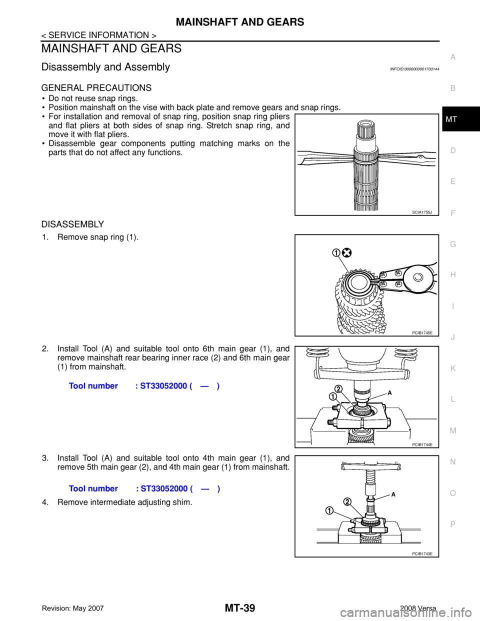
• For installation and removal of snap ring, position snap ring pliers
and flat pliers at both sides of snap ring. Stretch snap ring, and
move it with flat pliers.
• Disassemble gear components putting matching marks on the
parts that do not affect any functions.
DISASSEMBLY
1. Remove snap ring (1).
2. Install Tool (A) and suitable tool onto 6th main gear (1), and
remove mainshaft rear bearing inner race (2) and 6th main gear
(1) from mainshaft.
3. Install Tool (A) and suitable tool onto 4th main gear (1), and
remove 5th main gear (2), and 4th main gear (1) from mainshaft.
4. Remove intermediate adjusting shim.
SCIA1755J
PCIB1745E
Tool number : ST33052000 ( — )
PCIB1744E
Tool number : ST33052000 ( — )
PCIB1743E
Page 2328 of 2771

MT-40
< SERVICE INFORMATION >
MAINSHAFT AND GEARS
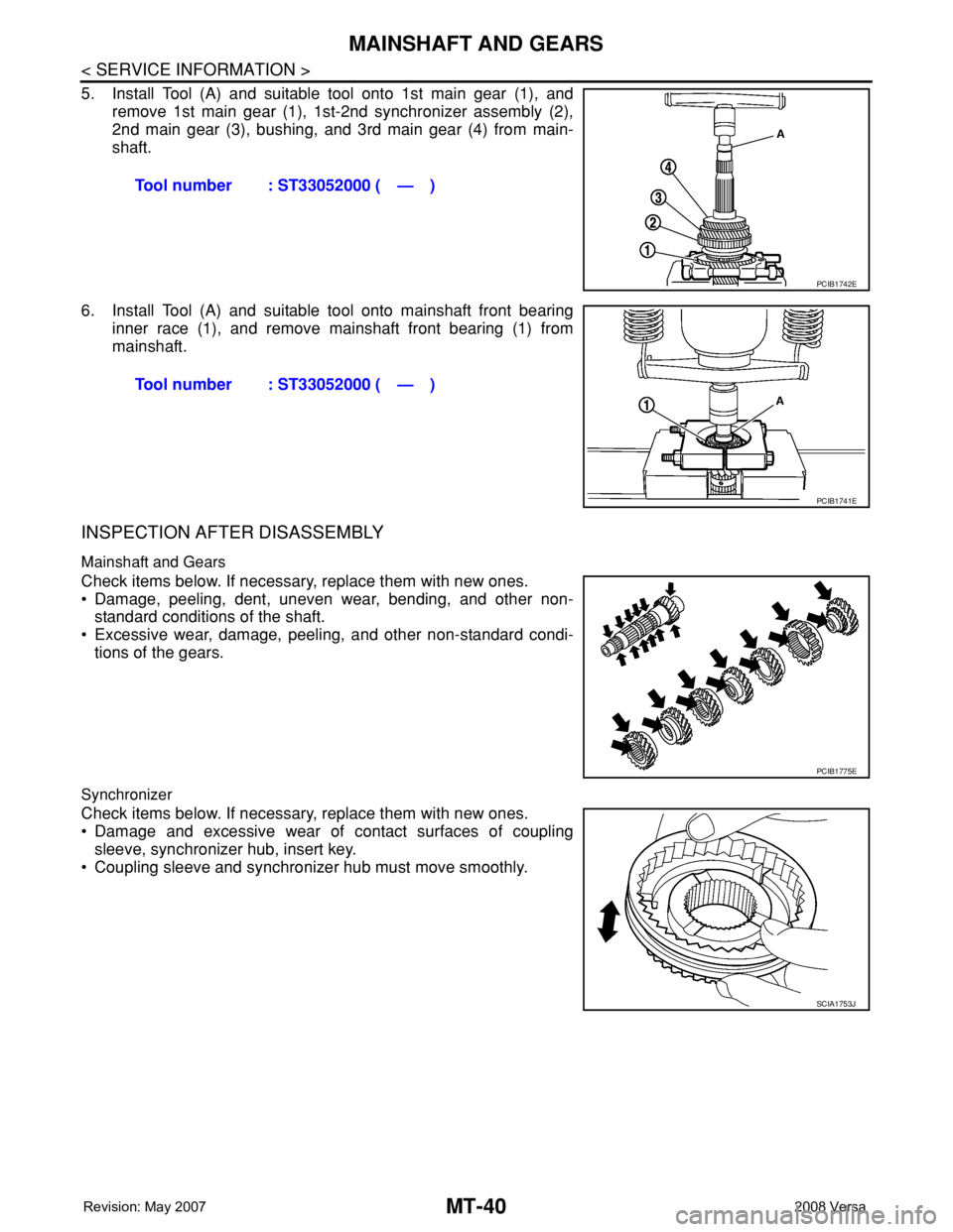
5. Install Tool (A) and suitable tool onto 1st main gear (1), and
remove 1st main gear (1), 1st-2nd synchronizer assembly (2),
2nd main gear (3), bushing, and 3rd main gear (4) from main-
shaft.
6. Install Tool (A) and suitable tool onto mainshaft front bearing
inner race (1), and remove mainshaft front bearing (1) from
mainshaft.
INSPECTION AFTER DISASSEMBLY
Mainshaft and Gears
Check items below. If necessary, replace them with new ones.
• Damage, peeling, dent, uneven wear, bending, and other non-
standard conditions of the shaft.
• Excessive wear, damage, peeling, and other non-standard condi-
tions of the gears.
Synchronizer
Check items below. If necessary, replace them with new ones.
• Damage and excessive wear of contact surfaces of coupling
sleeve, synchronizer hub, insert key.
• Coupling sleeve and synchronizer hub must move smoothly.Tool number : ST33052000 ( — )
PCIB1742E
Tool number : ST33052000 ( — )
PCIB1741E
PCIB1775E
SCIA1753J
Page 2329 of 2771

MAINSHAFT AND GEARS
MT-41
< SERVICE INFORMATION >
D
E
F
G
H
I
J
K
L
MA
B
MT
N
O
P
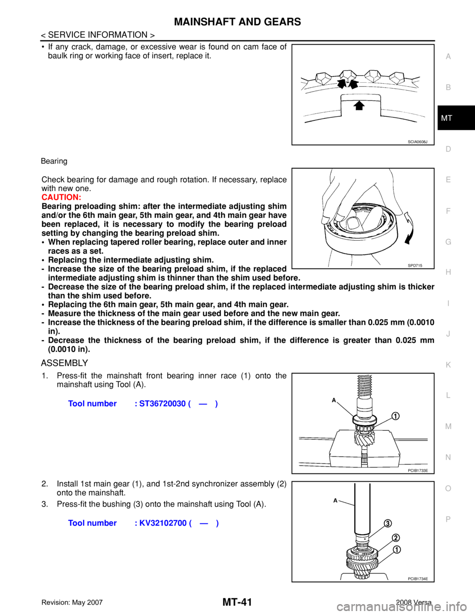
• If any crack, damage, or excessive wear is found on cam face of
baulk ring or working face of insert, replace it.
Bearing
Check bearing for damage and rough rotation. If necessary, replace
with new one.
CAUTION:
Bearing preloading shim: after the intermediate adjusting shim
and/or the 6th main gear, 5th main gear, and 4th main gear have
been replaced, it is necessary to modify the bearing preload
setting by changing the bearing preload shim.
• When replacing tapered roller bearing, replace outer and inner
races as a set.
• Replacing the intermediate adjusting shim.
- Increase the size of the bearing preload shim, if the replaced
intermediate adjusting shim is thinner than the shim used before.
- Decrease the size of the bearing preload shim, if the replaced intermediate adjusting shim is thicker
than the shim used before.
• Replacing the 6th main gear, 5th main gear, and 4th main gear.
- Measure the thickness of the main gear used before and the new main gear.
- Increase the thickness of the bearing preload shim, if the difference is smaller than 0.025 mm (0.0010
in).
- Decrease the thickness of the bearing preload shim, if the difference is greater than 0.025 mm
(0.0010 in).
ASSEMBLY
1. Press-fit the mainshaft front bearing inner race (1) onto the
mainshaft using Tool (A).
2. Install 1st main gear (1), and 1st-2nd synchronizer assembly (2)
onto the mainshaft.
3. Press-fit the bushing (3) onto the mainshaft using Tool (A).
SCIA0608J
SPD715
Tool number : ST36720030 ( — )
PCIB1733E
Tool number : KV32102700 ( — )
PCIB1734E
Page 2331 of 2771
MAINSHAFT AND GEARS
MT-43
< SERVICE INFORMATION >
D
E
F
G
H
I
J
K
L
MA
B
MT
N
O
P
9. Press-fit the 6th main gear (1) onto the mainshaft using Tool (A).
10. Press-fit the mainshaft rear bearing inner race (1) onto the main-
shaft using Tool (A).
11. Install snap ring onto mainshaft.Tool number : KV32102700 ( — )
PCIB1739E
Tool number : ST30901000 (J-26010-01)
PCIB1740E