Page 2333 of 2771
REVERSE IDLER SHAFT AND GEARS
MT-45
< SERVICE INFORMATION >
D
E
F
G
H
I
J
K
L
MA
B
MT
N
O
P
5. Remove needle bearings (1) from reverse idler shaft.
ASSEMBLY
Assembly is in the reverse order of disassembly.
CAUTION:
• Do not reuse snap ring.
• Make sure that snap ring is securely installed in the groove.
PCIB1761E
Page 2334 of 2771
MT-46
< SERVICE INFORMATION >
FINAL DRIVE
FINAL DRIVE
Disassembly and AssemblyINFOID:0000000001703146
DISASSEMBLY
1. Remove differential side bearing inner race (clutch housing side)
(1) using Tool (A) and suitable tool.
2. Remove speedometer drive gear.
3. Remove final gear bolts (1), and then separate the final gear (2)
from differential case.
4. Remove differential side bearing inner race (transaxle case
side) (1) using suitable tool (A).
5. Remove lock ring (1) from differential case.
6. Remove pinion mate shaft, pinion mate gears, side gears and
thrust washer from differential case.
INSPECTION AFTER DISASSEMBLY
Gear, Washer, Shaft and Case
Tool number : ST33061000 (J-8107-2)
PCIB1767E
PCIB1766E
PCIB1765E
PCIB1764E
Page 2335 of 2771

FINAL DRIVE
MT-47
< SERVICE INFORMATION >
D
E
F
G
H
I
J
K
L
MA
B
MT
N
O
P
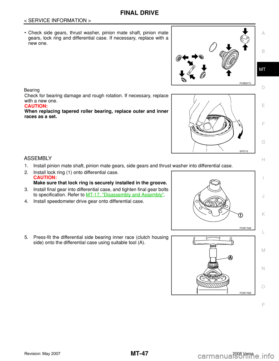
• Check side gears, thrust washer, pinion mate shaft, pinion mate
gears, lock ring and differential case. If necessary, replace with a
new one.
Bearing
Check for bearing damage and rough rotation. If necessary, replace
with a new one.
CAUTION:
When replacing tapered roller bearing, replace outer and inner
races as a set.
ASSEMBLY
1. Install pinion mate shaft, pinion mate gears, side gears and thrust washer into differential case.
2. Install lock ring (1) onto differential case.
CAUTION:
Make sure that lock ring is securely installed in the groove.
3. Install final gear into differential case, and tighten final gear bolts
to specification. Refer to MT-17, "
Disassembly and Assembly".
4. Install speedometer drive gear onto differential case.
5. Press-fit the differential side bearing inner race (clutch housing
side) onto the differential case using suitable tool (A).
PCIB0977J
SPD715
PCIB1764E
PCIB1762E
Page 2336 of 2771
MT-48
< SERVICE INFORMATION >
FINAL DRIVE
6. Press-fit the differential side bearing inner race (transaxle case
side) onto the differential case using suitable tool (A).
PCIB1763E
Page 2525 of 2771
RAX-1
DRIVELINE/AXLE
C
E
F
G
H
I
J
K
L
M
SECTION RAX
A
B
RAX
N
O
P
CONTENTS
REAR AXLE
SERVICE INFORMATION ............................2
PREPARATION ...................................................2
Commercial Service Tool ..........................................2
NOISE, VIBRATION AND HARSHNESS
(NVH) TROUBLESHOOTING .............................
3
NVH Troubleshooting Chart ......................................3
WHEEL HUB ......................................................4
On-Vehicle Inspection and Service ..........................4
Removal and Installation ..........................................4
SERVICE DATA AND SPECIFICATIONS
(SDS) ..................................................................
6
Wheel Bearing ..........................................................6
Page 2527 of 2771
NOISE, VIBRATION AND HARSHNESS (NVH) TROUBLESHOOTING
RAX-3
< SERVICE INFORMATION >
C
E
F
G
H
I
J
K
L
MA
B
RAX
N
O
P
NOISE, VIBRATION AND HARSHNESS (NVH) TROUBLESHOOTING
NVH Troubleshooting ChartINFOID:0000000001703711
Use chart below to help you find the cause of the symptom. If necessary, repair or replace these parts.
×: ApplicableReference page
RAX-4—
RAX-4
RSU-4, "
NVH Troubleshooting Chart
"
WT-4, "
NVH Troubleshooting Chart
"
WT-4, "
NVH Troubleshooting Chart
"
BR-4, "
NVH Troubleshooting Chart
"
PS-5, "
NVH Troubleshooting Chart
"
Possible cause and SUSPECTED PARTS
Improper installation, looseness
Parts interference
Wheel bearing damage
REAR SUSPENSION
TIRES
ROAD WHEEL
BRAKES
STEERING
Symptom REAR AXLENoise×× ×××××
Shake×× ×××××
Vibration×× ×× ×
Shimmy×× ×××××
Shudder× ×××××
Poor quality ride or handling××××××
Page 2528 of 2771

RAX-4
< SERVICE INFORMATION >
WHEEL HUB
WHEEL HUB
On-Vehicle Inspection and ServiceINFOID:0000000001703712
• Check the axle and suspension parts for excessive play, wear, or damage.
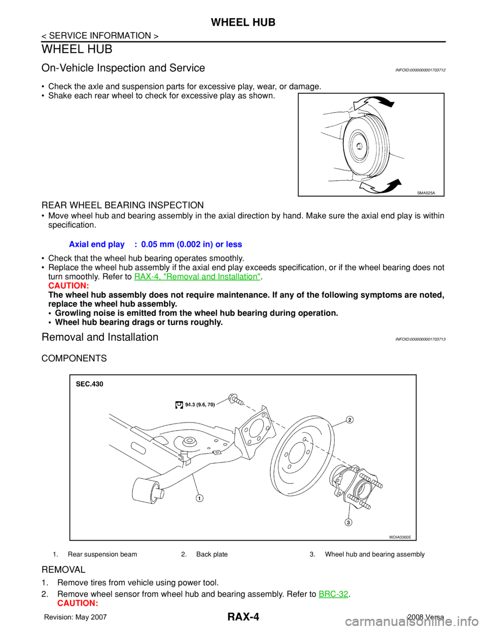
• Shake each rear wheel to check for excessive play as shown.
REAR WHEEL BEARING INSPECTION
• Move wheel hub and bearing assembly in the axial direction by hand. Make sure the axial end play is within
specification.
• Check that the wheel hub bearing operates smoothly.
• Replace the wheel hub assembly if the axial end play exceeds specification, or if the wheel bearing does not
turn smoothly. Refer to RAX-4, "
Removal and Installation".
CAUTION:
The wheel hub assembly does not require maintenance. If any of the following symptoms are noted,
replace the wheel hub assembly.
• Growling noise is emitted from the wheel hub bearing during operation.
• Wheel hub bearing drags or turns roughly.
Removal and InstallationINFOID:0000000001703713
COMPONENTS
REMOVAL
1. Remove tires from vehicle using power tool.
2. Remove wheel sensor from wheel hub and bearing assembly. Refer to BRC-32
.
CAUTION:
SMA525A
Axial end play : 0.05 mm (0.002 in) or less
1. Rear suspension beam 2. Back plate 3. Wheel hub and bearing assembly
WDIA0360E
Page 2529 of 2771
WHEEL HUB
RAX-5
< SERVICE INFORMATION >
C
E
F
G
H
I
J
K
L
MA
B
RAX
N
O
P
Do not pull on wheel sensor harness.
3. Remove the drum brake assembly. Refer to BR-29, "
Removal and Installation of Drum Brake Assembly".
4. Remove wheel hub and bearing assembly bolts, and then remove wheel hub and bearing assembly from
vehicle.
5. If necessary remove back plate, following procedure.
1. Remove parking brake rear cable from back plate. Refer to PB-4
.
2. Separate brake tube from wheel cylinder. Refer to BR-10
.
INSPECTION AFTER REMOVAL
Check for any deformity, cracks, or other damage on the wheel hub assembly, replace if necessary.
CAUTION:
The wheel hub assembly does not require maintenance. If any of the following symptoms are noted,
replace the wheel hub assembly.
• Growling noise is emitted from the wheel hub bearing during operation.
• Wheel hub bearing drags or turns roughly.
INSTALLATION
Installation is in the reverse order of removal.