Page 1819 of 2771
FRONT DRIVE SHAFT
FAX-23
< SERVICE INFORMATION >
C
E
F
G
H
I
J
K
L
MA
B
FA X
N
O
P Support Bearing
1. Install new dust shield on drive shaft
CAUTION:
Do not reuse dust shield.
2. Press support bearing onto drive shaft.
3. Install new snap ring.
CAUTION:
Do not reuse snap ring.
4. Install new dust shield
CAUTION:
Do not reuse dust shield.
Damper
1. Secure damper with new damper bands.
CAUTION:
Do not reuse damper bands.
YA X 0 0 7
YA X 0 0 8
“A”Except for CVT
models: 230 – 236 mm (9.06 – 9.29 in)
CVT models : 225 – 231 mm (8.86 – 9.09 in)
“B” : 70 mm (2.76 in)
FAC0156D
Page 1840 of 2771
 of e")
FSU-6
< SERVICE INFORMATION >
FRONT SUSPENSION ASSEMBLY
FRONT SUSPENSION ASSEMBLY
On-Vehicle Inspection and ServiceINFOID:0000000001703721
Make sure the mounting conditions (looseness, back lash) of each component and component conditions
(wear, damage) are normal.
INSPECTION OF LOWER BALL JOINT END PLAY
1. Set front wheels in a straight-ahead position. Do not depress brake pedal.
2. Place an iron bar or similar tool between transverse link and steering knuckle.
3. Measure axial end play by prying it up and down.
CAUTION:
Be careful not to damage ball joint boot. Do not damage the installation position by applying
excessive force.
STRUT INSPECTION
Check for oil leakage, damage and replace as necessary.
Wheel Alignment InspectionINFOID:0000000001703722
PRELIMINARY INSPECTION
WARNING:
Always adjust the alignment with the vehicle on a flat surface.
NOTE:
If alignment is out of specification, inspect and replace any damaged or worn rear suspension parts before
making any adjustments.
1. Check and adjust the wheel alignment with the vehicle under unladen conditions. “Unladen conditions”
means that the fuel, coolant, and lubricant are full; and that the spare tire, jack, hand tools and mats are in
their designated positions.
2. Check the tires for incorrect air pressure and excessive wear.
3. Check the wheels for run out and damage. Refer to WT-5, "
Inspection" .
4. Check the wheel bearing axial end play. Refer to FA X - 5 , "
On-Vehicle Inspection and Service" .
5. Check the shock absorbers for leaks or damage.
6. Check each mounting point of the suspension components for any excessive looseness or damage.
7. Check each link, arm, and the suspension member for any damage.
8. Check the vehicle height. Refer to FSU-17, "
Wheelarch Height (Unladen*)" .
GENERAL INFORMATION AND RECOMMENDATIONS
1. A Four-Wheel Thrust Alignment should be performed.
• This type of alignment is recommended for any NISSAN vehicle.
• The four-wheel “thrust” process helps ensure that the vehicle is properly aligned and the steering wheel
is centered.
• The alignment machine itself should be capable of accepting any NISSAN vehicle.
• The alignment machine should be checked to ensure that it is level.
2. Make sure the alignment machine is properly calibrated.
• Your alignment machine should be regularly calibrated in order to give correct information.
• Check with the manufacturer of your specific alignment machine for their recommended Service/Cali-
bration Schedule.
THE ALIGNMENT PROCESS
IMPORTANT: Use only the alignment specifications listed in this Service Manual. Refer to FSU-16, "Wheel
Alignment (Unladen*)" .
1. When displaying the alignment settings, many alignment machines use “indicators”: (Green/red, plus or
minus, Go/No Go). Do NOT use these indicators.
• The alignment specifications programmed into your alignment machine that operate these indicators
may not be correct.Axial end play : 0 mm (0 in)
Page 1843 of 2771
FRONT SUSPENSION ASSEMBLY
FSU-9
< SERVICE INFORMATION >
C
D
F
G
H
I
J
K
L
MA
B
FSU
N
O
P
ComponentINFOID:0000000001703723
1. Strut mounting insulator 2. Strut mounting bearing 3. Coil spring
4. Bound bumper 5. Strut 6. Steering knuckle
7. Stabilizer clamp 8. Stabilizer bushing 9. Stabilizer connecting rod
10. Transverse link 11. Stabilizer bar 12. Upper link (left)
WEIA0211E
Page 1846 of 2771
 to strut and secure it in a vise.
CAUTION:
When installing the strut attachment to strut, wrap a shop
cloth around strut to pro")
FSU-12
< SERVICE INFORMATION >
COIL SPRING AND STRUT
1. Install Tool (A) to strut and secure it in a vise.
CAUTION:
When installing the strut attachment to strut, wrap a shop
cloth around strut to protect it from damage.
2. Using a spring compressor (commercial service tool), compress
coil spring between strut mounting bearing and spring lower
seat (on strut) until coil spring is free.
CAUTION:
Be sure the spring compressor is securely attached to the
coil spring before compressing coil spring.
3. Make sure coil spring with spring compressor between strut
mounting bearing and spring lower seat (strut) is free. Then
remove piston rod lock nut while securing the piston rod tip so
that piston rod does not turn.
4. Remove strut mounting insulator, strut mounting bearing, and
bound bumper from strut.
5. Remove coil spring with spring compressor, and then gradually release a spring compressor.
CAUTION:
Loosen while making sure coil spring attachment position does not move.
6. Remove the strut attachment from strut.
INSPECTION AFTER DISASSEMBLY
Strut Inspection
Check the following:
• Strut for deformation, cracks or damage, and replace it if necessary.
• Piston rod for damage, uneven wear or distortion, and replace it if necessary.
• For oil leakage, and replace it if necessary.
Strut Mounting Insulator and Rubber Parts Inspection
Check strut mounting insulator for cracks and rubber parts for wear. Replace it if malfunction is detected.
Coil Spring Inspection
Check coil spring for cracks, wear or damage, and replace it if necessary.
ASSEMBLY
CAUTION:
Do not damage strut piston rod when installing components to strut.
1. Install the Tool (A) to strut and secure it in a vise.
CAUTION:
When installing the strut attachment to strut, wrap a shop
cloth around strut to protect it from damage.Tool number : ST35652000 ( — )
WEIA0180E
SEIA0297E
Tool number : ST35652000 ( — )
WEIA0180E
Page 1847 of 2771
COIL SPRING AND STRUT
FSU-13
< SERVICE INFORMATION >
C
D
F
G
H
I
J
K
L
MA
B
FSU
N
O
P
2. Compress coil spring using a spring compressor (commercial
service tool), and install it onto strut.
CAUTION:
• Face tube side of coil spring downward. Align the lower
end to spring lower seat as shown.
• Be sure spring compressor is securely attached to coil
spring. Compress coil spring.
3. Apply soapy water to bound bumper. Insert bound bumper into
strut mounting insulator.
CAUTION:
Do not use machine oil.
4. Attach strut mounting bearing and strut mounting insulator.
• Installation position of strut mounting insulator as shown.
5. Secure piston rod tip so that piston rod does not turn, then
tighten piston rod lock nut to specified torque.
6. Gradually release a spring compressor, and remove coil spring.
CAUTION:
Loosen while making sure coil spring attachment position
does not move.
7. Remove the strut attachment from strut.
SEIA0297E
MEIA0016E
MEIA0014E
Page 1854 of 2771

PRECAUTIONS
GI-3
< SERVICE INFORMATION >
C
D
E
F
G
H
I
J
K
L
MB
GI
N
O
P
General PrecautionINFOID:0000000001702424
• Do not operate the engine for an extended period of time without
proper exhaust ventilation.
Keep the work area well ventilated and free of any flammable
materials. Special care should be taken when handling any flam-
mable or poisonous materials, such as gasoline, refrigerant gas,
etc. When working in a pit or other enclosed area, be sure to prop-
erly ventilate the area before working with hazardous materials.
Do not smoke while working on the vehicle.
• Before jacking up the vehicle, apply wheel chocks or other tire
blocks to the wheels to prevent the vehicle from moving. After jack-
ing up the vehicle, support the vehicle weight with safety stands at
the points designated for proper lifting before working on the vehi-
cle.
These operations should be done on a level surface.
• When removing a heavy component such as the engine or tran-
saxle/transmission, be careful not to lose your balance and drop
them. Also, do not allow them to strike adjacent parts, especially
the brake tubes and master cylinder.
• Before starting repairs which do not require battery power:
Turn off ignition switch.
Disconnect the negative battery terminal.
• If the battery terminals are disconnected, recorded memory of
radio and each control unit is erased.
• Battery posts, terminals and related accessories contain lead and
lead compounds. Wash hands after handling.
• To prevent serious burns:
Avoid contact with hot metal parts.
Do not remove the radiator cap when the engine is hot.
• Dispose of or recycle drained oil or the solvent used for cleaning
parts in an appropriate manner.
• Do not attempt to top off the fuel tank after the fuel pump nozzle
shuts off automatically.
Continued refueling may cause fuel overflow, resulting in fuel spray
and possibly a fire.
• Clean all disassembled parts in the designated liquid or solvent
prior to inspection or assembly.
• Replace oil seals, gaskets, packings, O-rings, locking washers,
cotter pins, self-locking nuts, etc. with new ones.
• Replace inner and outer races of tapered roller bearings and needle bearings as a set.
• Arrange the disassembled parts in accordance with their assembled locations and sequence.
• Do not touch the terminals of electrical components which use microcomputers (such as ECM).
Static electricity may damage internal electronic components.
• After disconnecting vacuum or air hoses, attach a tag to indicate the proper connection.
• Use only the fluids and lubricants specified in this manual.
• Use approved bonding agent, sealants or their equivalents when required.
SGI285
SGI231
SEF289H
SGI233
Page 2285 of 2771
CHASSIS AND BODY MAINTENANCE
MA-25
< SERVICE INFORMATION >
C
D
E
F
G
H
I
J
K
MA
B
MA
N
O
P
Check the brake pads for wear or damage. Refer to BR-32, "Disas-
sembly and Assembly of Wheel Cylinder" .
WHEEL CYLINDER
Check for leakage.
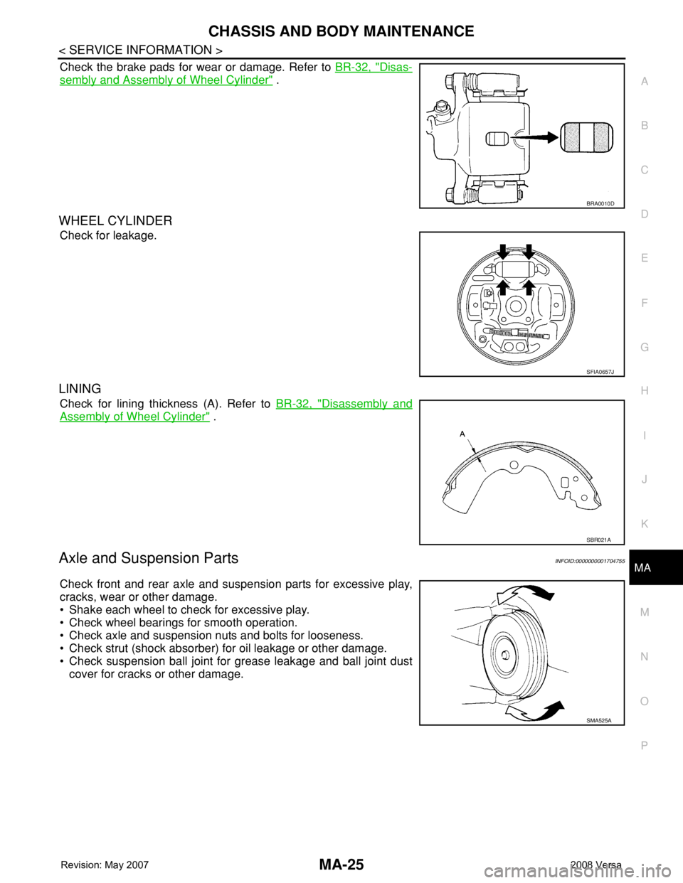
LINING
Check for lining thickness (A). Refer to BR-32, "Disassembly and
Assembly of Wheel Cylinder" .
Axle and Suspension PartsINFOID:0000000001704755
Check front and rear axle and suspension parts for excessive play,
cracks, wear or other damage.
• Shake each wheel to check for excessive play.
• Check wheel bearings for smooth operation.
• Check axle and suspension nuts and bolts for looseness.
• Check strut (shock absorber) for oil leakage or other damage.
• Check suspension ball joint for grease leakage and ball joint dust
cover for cracks or other damage.
BRA0010D
SFIA0657J
SBR021A
SMA525A
Page 2291 of 2771

PREPARATION
MT-3
< SERVICE INFORMATION >
D
E
F
G
H
I
J
K
L
MA
B
MT
N
O
P
PREPARATION
Special Service ToolINFOID:0000000001703130
The actual shapes of Kent-Moore tools may differ from those of special service tools illustrated here.
Tool number
(Kent-Moore No.)
Tool nameDescription
KV381054S0
(J-34286)
PullerRemoving mainshaft front bearing outer race
KV38100200
(—)
Drift• Installing mainshaft front bearing outer race
• Installing mainshaft rear bearing outer race
• Installing differential side bearing outer race
(clutch housing side)
a: 65 mm (2.56 in) dia.
b: 49 mm (1.93 in) dia.
ST33220000
(—)
DriftInstalling input shaft oil seal
a: 37 mm (1.46 in) dia.
b: 31 mm (1.22 in) dia.
c: 22 mm (0.87 in) dia.
ST33400001
(J-26082)
DriftInstalling differential side bearing outer race
(transaxle case side)
a: 60 mm (2.36 in) dia.
b: 47 mm (1.85 in) dia.
KV38100300
(J-25523)
DriftInstalling differential side oil seal
a: 54 mm (2.13 in) dia.
b: 46 mm (1.81 in) dia.
c: 32 mm (1.26 in) dia.
ST36720030
(—)
Drift• Installing input shaft rear bearing
• Installing mainshaft front bearing inner race
a: 70 mm (2.76 in) dia.
b: 40 mm (1.57 in) dia.
c: 29 mm (1.14 in) dia.
ZZA0601D
ZZA1143D
ZZA1046D
ZZA0814D
ZZA1046D
ZZA0978D


, and install it onto strut.
CAUTION:
�")