2008 NISSAN TIIDA bearing
[x] Cancel search: bearingPage 1786 of 2771
SERVICE DATA AND SPECIFICATIONS (SDS)
EM-109
< SERVICE INFORMATION >
C
D
E
F
G
H
I
J
K
L
MA
EM
N
P O
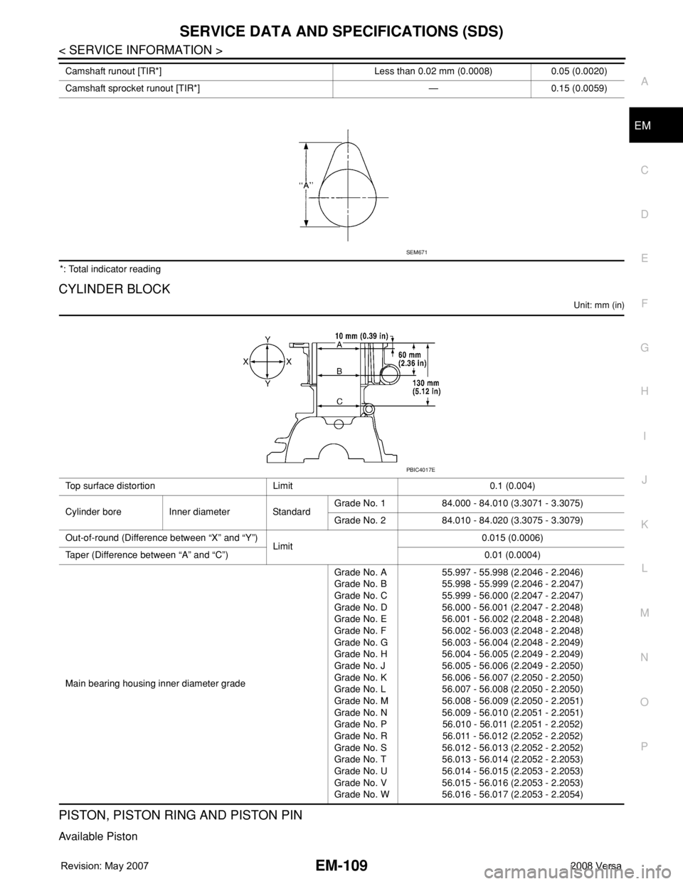
*: Total indicator reading
CYLINDER BLOCK
Unit: mm (in)
PISTON, PISTON RING AND PISTON PIN
Available Piston
Camshaft runout [TIR*] Less than 0.02 mm (0.0008) 0.05 (0.0020)
Camshaft sprocket runout [TIR*] — 0.15 (0.0059)
SEM671
Top surface distortion Limit 0.1 (0.004)
Cylinder bore Inner diameter StandardGrade No. 1 84.000 - 84.010 (3.3071 - 3.3075)
Grade No. 2 84.010 - 84.020 (3.3075 - 3.3079)
Out-of-round (Difference between “X” and “Y”)
Limit0.015 (0.0006)
Taper (Difference between “A” and “C”) 0.01 (0.0004)
Main bearing housing inner diameter gradeGrade No. A
Grade No. B
Grade No. C
Grade No. D
Grade No. E
Grade No. F
Grade No. G
Grade No. H
Grade No. J
Grade No. K
Grade No. L
Grade No. M
Grade No. N
Grade No. P
Grade No. R
Grade No. S
Grade No. T
Grade No. U
Grade No. V
Grade No. W55.997 - 55.998 (2.2046 - 2.2046)
55.998 - 55.999 (2.2046 - 2.2047)
55.999 - 56.000 (2.2047 - 2.2047)
56.000 - 56.001 (2.2047 - 2.2048)
56.001 - 56.002 (2.2048 - 2.2048)
56.002 - 56.003 (2.2048 - 2.2048)
56.003 - 56.004 (2.2048 - 2.2049)
56.004 - 56.005 (2.2049 - 2.2049)
56.005 - 56.006 (2.2049 - 2.2050)
56.006 - 56.007 (2.2050 - 2.2050)
56.007 - 56.008 (2.2050 - 2.2050)
56.008 - 56.009 (2.2050 - 2.2051)
56.009 - 56.010 (2.2051 - 2.2051)
56.010 - 56.011 (2.2051 - 2.2052)
56.011 - 56.012 (2.2052 - 2.2052)
56.012 - 56.013 (2.2052 - 2.2052)
56.013 - 56.014 (2.2052 - 2.2053)
56.014 - 56.015 (2.2053 - 2.2053)
56.015 - 56.016 (2.2053 - 2.2053)
56.016 - 56.017 (2.2053 - 2.2054)
PBIC4017E
Page 1789 of 2771
EM-112
< SERVICE INFORMATION >
SERVICE DATA AND SPECIFICATIONS (SDS)
*: Total indicator reading
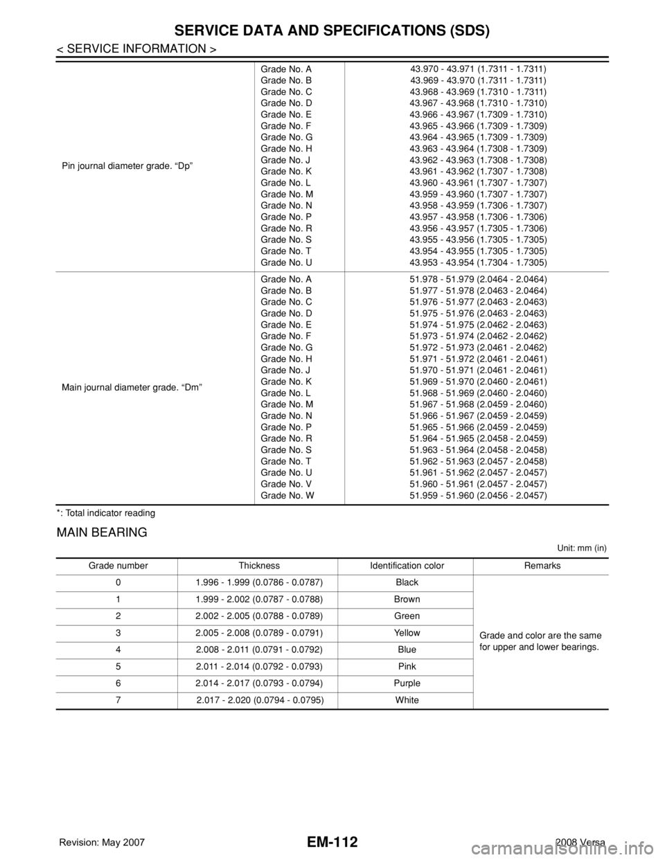
MAIN BEARING
Unit: mm (in)
Pin journal diameter grade. “Dp”Grade No. A
Grade No. B
Grade No. C
Grade No. D
Grade No. E
Grade No. F
Grade No. G
Grade No. H
Grade No. J
Grade No. K
Grade No. L
Grade No. M
Grade No. N
Grade No. P
Grade No. R
Grade No. S
Grade No. T
Grade No. U43.970 - 43.971 (1.7311 - 1.7311)
43.969 - 43.970 (1.7311 - 1.7311)
43.968 - 43.969 (1.7310 - 1.7311)
43.967 - 43.968 (1.7310 - 1.7310)
43.966 - 43.967 (1.7309 - 1.7310)
43.965 - 43.966 (1.7309 - 1.7309)
43.964 - 43.965 (1.7309 - 1.7309)
43.963 - 43.964 (1.7308 - 1.7309)
43.962 - 43.963 (1.7308 - 1.7308)
43.961 - 43.962 (1.7307 - 1.7308)
43.960 - 43.961 (1.7307 - 1.7307)
43.959 - 43.960 (1.7307 - 1.7307)
43.958 - 43.959 (1.7306 - 1.7307)
43.957 - 43.958 (1.7306 - 1.7306)
43.956 - 43.957 (1.7305 - 1.7306)
43.955 - 43.956 (1.7305 - 1.7305)
43.954 - 43.955 (1.7305 - 1.7305)
43.953 - 43.954 (1.7304 - 1.7305)
Main journal diameter grade. “Dm”Grade No. A
Grade No. B
Grade No. C
Grade No. D
Grade No. E
Grade No. F
Grade No. G
Grade No. H
Grade No. J
Grade No. K
Grade No. L
Grade No. M
Grade No. N
Grade No. P
Grade No. R
Grade No. S
Grade No. T
Grade No. U
Grade No. V
Grade No. W51.978 - 51.979 (2.0464 - 2.0464)
51.977 - 51.978 (2.0463 - 2.0464)
51.976 - 51.977 (2.0463 - 2.0463)
51.975 - 51.976 (2.0463 - 2.0463)
51.974 - 51.975 (2.0462 - 2.0463)
51.973 - 51.974 (2.0462 - 2.0462)
51.972 - 51.973 (2.0461 - 2.0462)
51.971 - 51.972 (2.0461 - 2.0461)
51.970 - 51.971 (2.0461 - 2.0461)
51.969 - 51.970 (2.0460 - 2.0461)
51.968 - 51.969 (2.0460 - 2.0460)
51.967 - 51.968 (2.0459 - 2.0460)
51.966 - 51.967 (2.0459 - 2.0459)
51.965 - 51.966 (2.0459 - 2.0459)
51.964 - 51.965 (2.0458 - 2.0459)
51.963 - 51.964 (2.0458 - 2.0458)
51.962 - 51.963 (2.0457 - 2.0458)
51.961 - 51.962 (2.0457 - 2.0457)
51.960 - 51.961 (2.0457 - 2.0457)
51.959 - 51.960 (2.0456 - 2.0457)
Grade number Thickness Identification color Remarks
0 1.996 - 1.999 (0.0786 - 0.0787) Black
Grade and color are the same
for upper and lower bearings. 1 1.999 - 2.002 (0.0787 - 0.0788) Brown
2 2.002 - 2.005 (0.0788 - 0.0789) Green
3 2.005 - 2.008 (0.0789 - 0.0791) Yellow
4 2.008 - 2.011 (0.0791 - 0.0792) Blue
5 2.011 - 2.014 (0.0792 - 0.0793) Pink
6 2.014 - 2.017 (0.0793 - 0.0794) Purple
7 2.017 - 2.020 (0.0794 - 0.0795) White
Page 1790 of 2771
SERVICE DATA AND SPECIFICATIONS (SDS)
EM-113
< SERVICE INFORMATION >
C
D
E
F
G
H
I
J
K
L
MA
EM
N
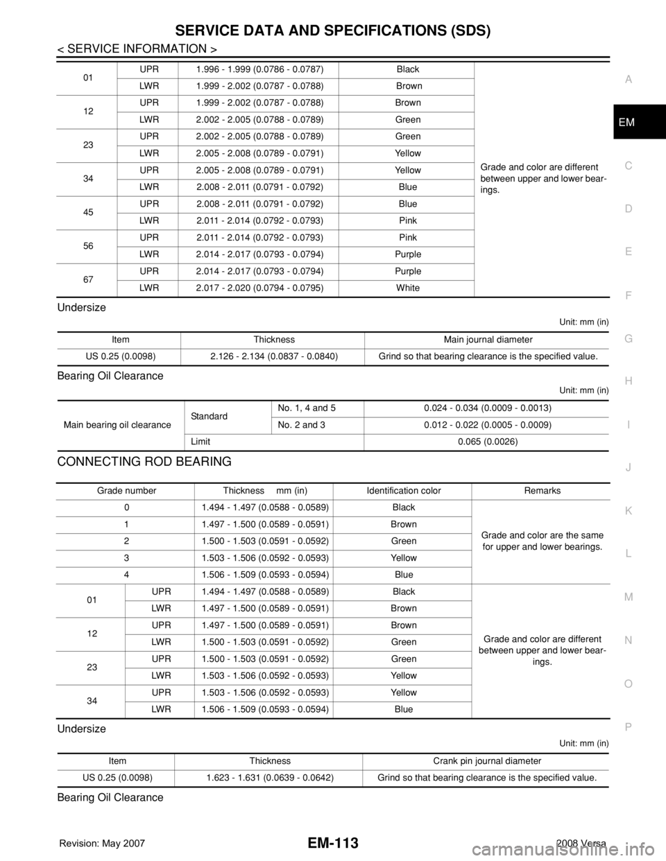
P O Undersize
Unit: mm (in)
Bearing Oil Clearance
Unit: mm (in)
CONNECTING ROD BEARING
Undersize
Unit: mm (in)
Bearing Oil Clearance
01UPR 1.996 - 1.999 (0.0786 - 0.0787) Black
Grade and color are different
between upper and lower bear-
ings. LWR 1.999 - 2.002 (0.0787 - 0.0788) Brown
12UPR 1.999 - 2.002 (0.0787 - 0.0788) Brown
LWR 2.002 - 2.005 (0.0788 - 0.0789) Green
23UPR 2.002 - 2.005 (0.0788 - 0.0789) Green
LWR 2.005 - 2.008 (0.0789 - 0.0791) Yellow
34UPR 2.005 - 2.008 (0.0789 - 0.0791) Yellow
LWR 2.008 - 2.011 (0.0791 - 0.0792) Blue
45UPR 2.008 - 2.011 (0.0791 - 0.0792) Blue
LWR 2.011 - 2.014 (0.0792 - 0.0793) Pink
56UPR 2.011 - 2.014 (0.0792 - 0.0793) Pink
LWR 2.014 - 2.017 (0.0793 - 0.0794) Purple
67UPR 2.014 - 2.017 (0.0793 - 0.0794) Purple
LWR 2.017 - 2.020 (0.0794 - 0.0795) White
Item Thickness Main journal diameter
US 0.25 (0.0098) 2.126 - 2.134 (0.0837 - 0.0840) Grind so that bearing clearance is the specified value.
Main bearing oil clearanceStandardNo. 1, 4 and 5 0.024 - 0.034 (0.0009 - 0.0013)
No. 2 and 3 0.012 - 0.022 (0.0005 - 0.0009)
Limit 0.065 (0.0026)
Grade number Thickness mm (in) Identification color Remarks
0 1.494 - 1.497 (0.0588 - 0.0589) Black
Grade and color are the same
for upper and lower bearings. 1 1.497 - 1.500 (0.0589 - 0.0591) Brown
2 1.500 - 1.503 (0.0591 - 0.0592) Green
3 1.503 - 1.506 (0.0592 - 0.0593) Yellow
4 1.506 - 1.509 (0.0593 - 0.0594) Blue
01UPR 1.494 - 1.497 (0.0588 - 0.0589) Black
Grade and color are different
between upper and lower bear-
ings. LWR 1.497 - 1.500 (0.0589 - 0.0591) Brown
12UPR 1.497 - 1.500 (0.0589 - 0.0591) Brown
LWR 1.500 - 1.503 (0.0591 - 0.0592) Green
23UPR 1.500 - 1.503 (0.0591 - 0.0592) Green
LWR 1.503 - 1.506 (0.0592 - 0.0593) Yellow
34UPR 1.503 - 1.506 (0.0592 - 0.0593) Yellow
LWR 1.506 - 1.509 (0.0593 - 0.0594) Blue
Item Thickness Crank pin journal diameter
US 0.25 (0.0098) 1.623 - 1.631 (0.0639 - 0.0642) Grind so that bearing clearance is the specified value.
Page 1791 of 2771
EM-114
< SERVICE INFORMATION >
SERVICE DATA AND SPECIFICATIONS (SDS)
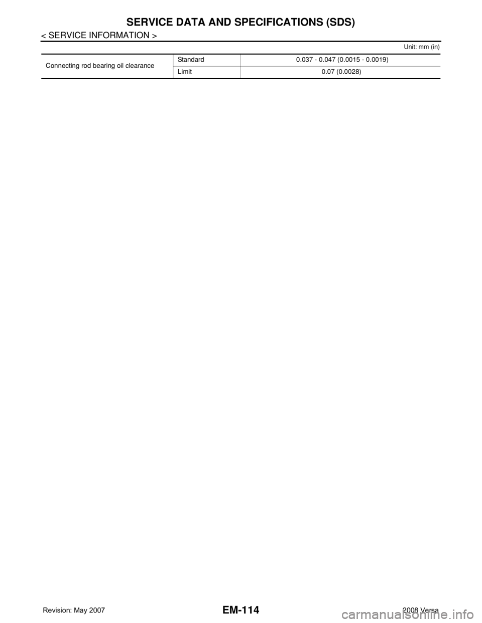
Unit: mm (in)
Connecting rod bearing oil clearanceStandard 0.037 - 0.047 (0.0015 - 0.0019)
Limit 0.07 (0.0028)
Page 1795 of 2771
EX-4
< SERVICE INFORMATION >
EXHAUST SYSTEM
EXHAUST SYSTEM
Checking Exhaust SystemINFOID:0000000001703106
Check exhaust pipes, muffler and mounting for improper attachment,
leaks, cracks, damage or deterioration.
• If necessary, repair or replace damaged parts.
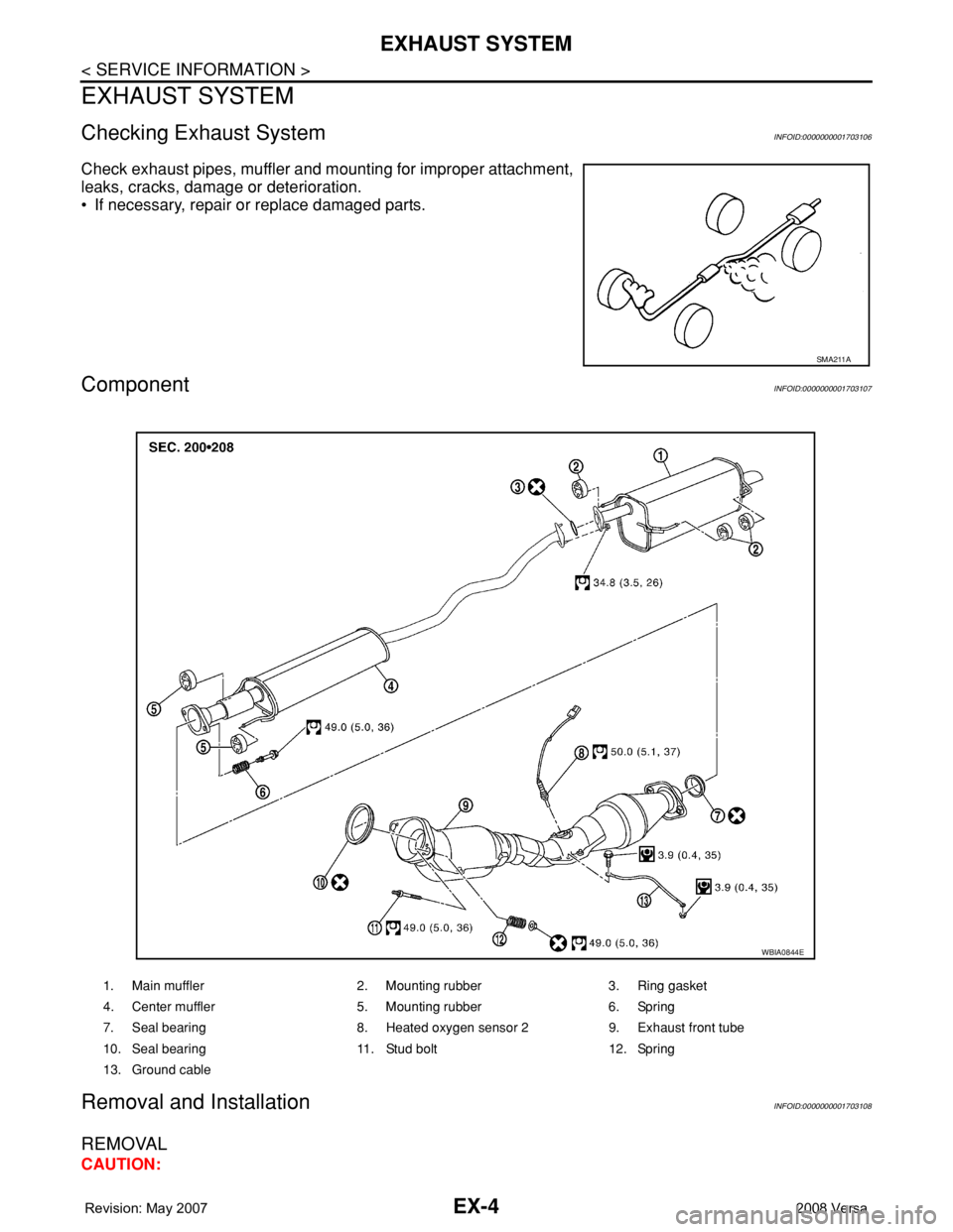
ComponentINFOID:0000000001703107
Removal and InstallationINFOID:0000000001703108
REMOVAL
CAUTION:
SMA211A
1. Main muffler 2. Mounting rubber 3. Ring gasket
4. Center muffler 5. Mounting rubber 6. Spring
7. Seal bearing 8. Heated oxygen sensor 2 9. Exhaust front tube
10. Seal bearing 11. Stud bolt 12. Spring
13. Ground cable
WBIA0844E
Page 1796 of 2771
EXHAUST SYSTEM
EX-5
< SERVICE INFORMATION >
C
D
E
F
G
H
I
J
K
L
MA
EX
N
P O
• Be sure to use genuine NISSAN exhaust system parts or equivalents which are specially designed
for heat resistance, corrosion resistance and shape.
• Perform the operation with the exhaust system fully cooled down because the system will be hot
just after the engine stops.
• Be careful not to cut your hand on heat insulator edge.
1. Disconnect harness connector of heated oxygen sensor 2.
• Using Tool, remove heated oxygen sensor 2.
CAUTION:
Be careful not to damage heated oxygen sensor 2.
a.2. Disconnect each joint and mounting rubber.
INSTALLATION
Installation is in the reverse order of removal.
CAUTION:
• Always replace exhaust gaskets and seal bearings with new ones when installing.
• Discard any heated oxygen sensor 2 which has been dropped from a height of more than 0.5 m (19.7
in) onto a hard surface such as a concrete floor; use a new one.
• Before installing a new heated oxygen sensor 2, clean exhaust system threads using the heated oxy-
gen sensor thread cleaner and apply anti-seize lubricant (commercial service tool).
• Do not over tighten heated oxygen sensor 2. Doing so may cause damage to the heated oxygen sen-
sor 2, resulting in the “MIL” coming on.
• Remove deposits from the sealing surface of each connection. Connect them securely to avoid
exhaust leakage.
• Temporarily tighten nuts on the exhaust manifold side and bolts on the vehicle side. Check each part
for unusual interference, and then tighten them to the specified torque.
• When installing each mounting rubber, avoid twisting or unusual extension in up/down and right/left
directions.
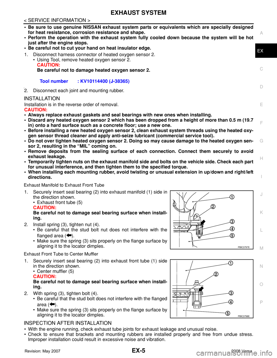
Exhaust Manifold to Exhaust Front Tube
1. Securely insert seal bearing (2) into exhaust manifold (1) side in
the direction shown.
• Exhaust front tube (5)
CAUTION:
Be careful not to damage seal bearing surface when install-
ing.
2. Install spring (3), tighten nut (4).
• Be careful that the stud bolt nut does not interfere with the
flanged area ( ).
• Make sure the spring (3) sits properly on the flange surface by
aligning it to the locator dimples.
Exhaust Front Tube to Center Muffler
1. Securely insert seal bearing (2) into exhaust front tube (1) side
in the direction shown.
• Center muffler (5)
CAUTION:
Be careful not to damage seal bearing surface when install-
ing.
2. With spring (3), tighten bolt (4).
• Be careful that the stud bolt does not interfere with the flanged
area ( ).
• Make sure the spring (3) sits properly on the flange surface by
aligning it to the locator dimples.
INSPECTION AFTER INSTALLATION
• With the engine running, check exhaust tube joints for exhaust leakage and unusual noise.
• Check to ensure that brackets and mounting rubbers are installed properly and free from undue stress.
Improper installation could result in excessive noise and vibration.Tool number : KV10114400 (J-38365)
PBIC3797E
PBIC3798E
Page 1800 of 2771
FAX-4
< SERVICE INFORMATION >
NOISE, VIBRATION AND HARSHNESS (NVH) TROUBLESHOOTING
NOISE, VIBRATION AND HARSHNESS (NVH) TROUBLESHOOTING
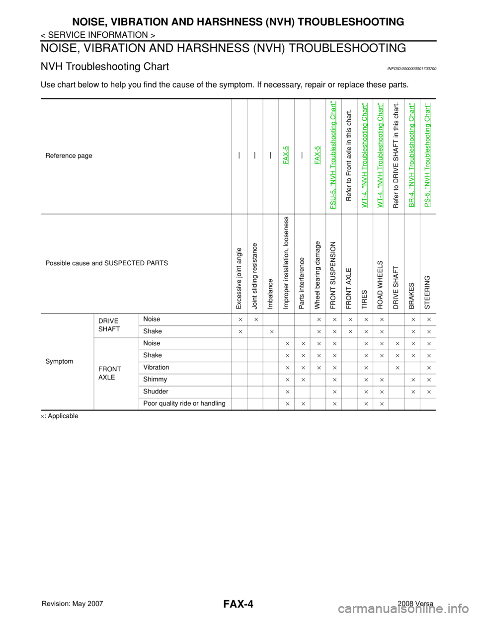
NVH Troubleshooting ChartINFOID:0000000001703700
Use chart below to help you find the cause of the symptom. If necessary, repair or replace these parts.
×: ApplicableReference page
—
—
—
FAX-5—
FAX-5
FSU-5, "
NVH Troubleshooting Chart
"
Refer to Front axle in this chart.
WT-4, "
NVH Troubleshooting Chart
"
WT-4, "
NVH Troubleshooting Chart
"
Refer to DRIVE SHAFT in this chart.
BR-4, "
NVH Troubleshooting Chart
"
PS-5, "
NVH Troubleshooting Chart
"
Possible cause and SUSPECTED PARTS
Excessive joint angle
Joint sliding resistance
Imbalance
Improper installation, looseness
Parts interference
Wheel bearing damage
FRONT SUSPENSION
FRONT AXLE
TIRES
ROAD WHEELS
DRIVE SHAFT
BRAKES
STEERING
SymptomDRIVE
SHAFTNoise×× ××××× ××
Shake× × ××××× ××
FRONT
AXLENoise×××× ×××××
Shake×××× ×××××
Vibration×××××××
Shimmy×××××××
Shudder× × ×× ××
Poor quality ride or handling×××××
Page 1801 of 2771
FRONT WHEEL HUB AND KNUCKLE
FAX-5
< SERVICE INFORMATION >
C
E
F
G
H
I
J
K
L
MA
B
FA X
N
O
P
FRONT WHEEL HUB AND KNUCKLE
On-Vehicle Inspection and ServiceINFOID:0000000001703701
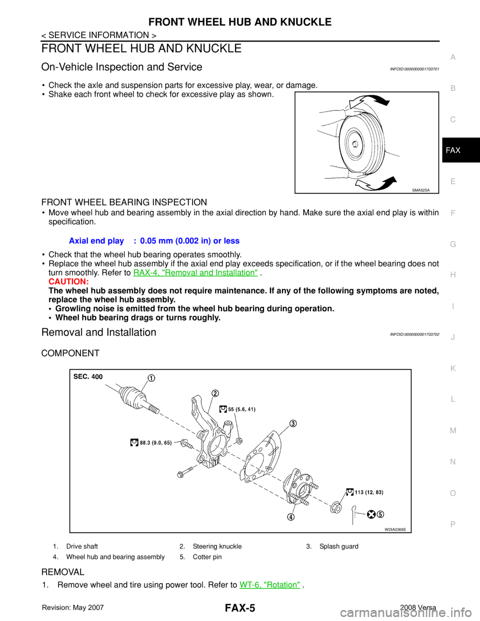
• Check the axle and suspension parts for excessive play, wear, or damage.
• Shake each front wheel to check for excessive play as shown.
FRONT WHEEL BEARING INSPECTION
• Move wheel hub and bearing assembly in the axial direction by hand. Make sure the axial end play is within
specification.
• Check that the wheel hub bearing operates smoothly.
• Replace the wheel hub assembly if the axial end play exceeds specification, or if the wheel bearing does not
turn smoothly. Refer to RAX-4, "
Removal and Installation" .
CAUTION:
The wheel hub assembly does not require maintenance. If any of the following symptoms are noted,
replace the wheel hub assembly.
• Growling noise is emitted from the wheel hub bearing during operation.
• Wheel hub bearing drags or turns roughly.
Removal and InstallationINFOID:0000000001703702
COMPONENT
REMOVAL
1. Remove wheel and tire using power tool. Refer to WT-6, "Rotation" .
SMA525A
Axial end play : 0.05 mm (0.002 in) or less
1. Drive shaft 2. Steering knuckle 3. Splash guard
4. Wheel hub and bearing assembly 5. Cotter pin
WDIA0366E