2008 NISSAN TIIDA fuse
[x] Cancel search: fusePage 1956 of 2771
REAR WINDOW DEFOGGER
GW-55
< SERVICE INFORMATION >
C
D
E
F
G
H
J
K
L
MA
B
GW
N
O
P
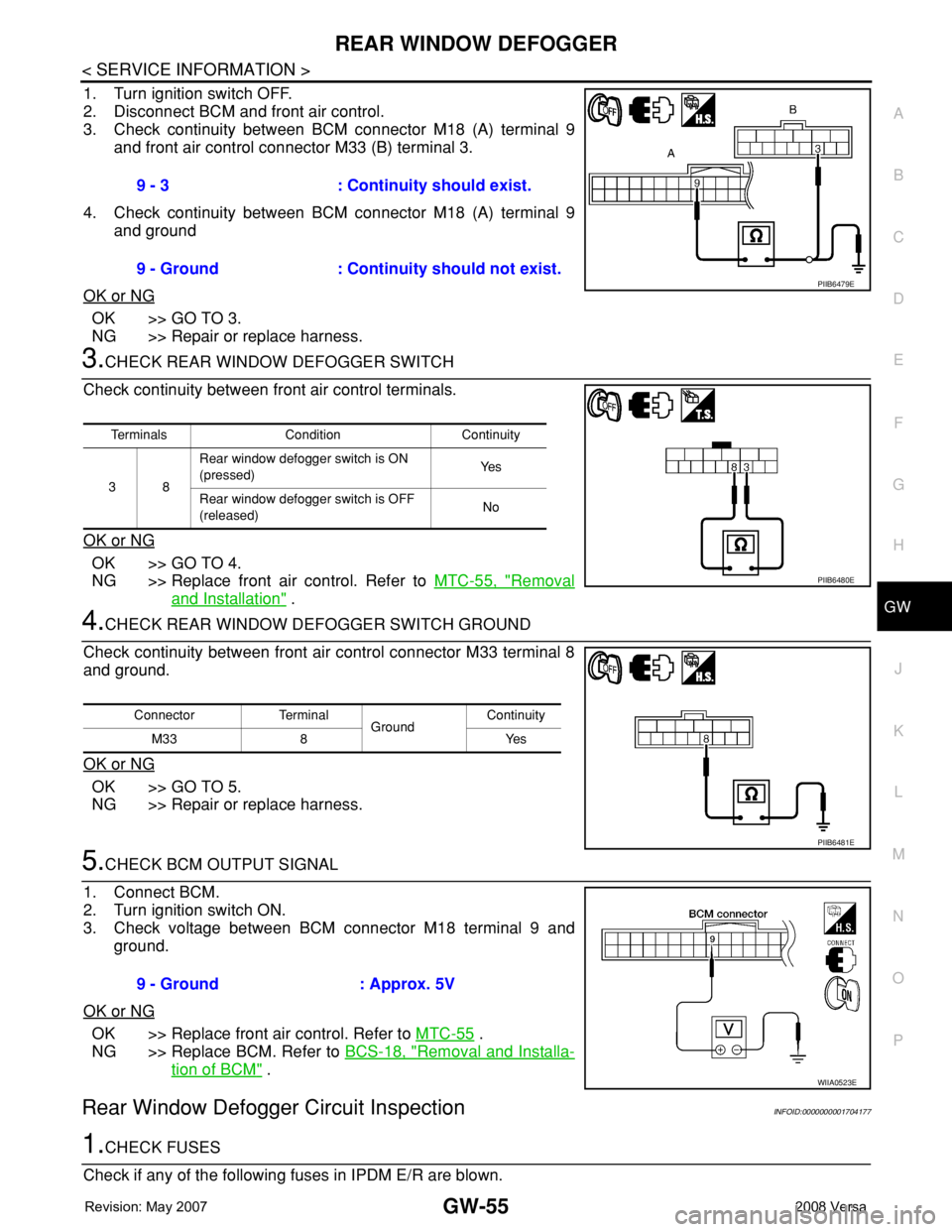
1. Turn ignition switch OFF.
2. Disconnect BCM and front air control.
3. Check continuity between BCM connector M18 (A) terminal 9
and front air control connector M33 (B) terminal 3.
4. Check continuity between BCM connector M18 (A) terminal 9
and ground
OK or NG
OK >> GO TO 3.
NG >> Repair or replace harness.
3.CHECK REAR WINDOW DEFOGGER SWITCH
Check continuity between front air control terminals.
OK or NG
OK >> GO TO 4.
NG >> Replace front air control. Refer to MTC-55, "
Removal
and Installation" .
4.CHECK REAR WINDOW DEFOGGER SWITCH GROUND
Check continuity between front air control connector M33 terminal 8
and ground.
OK or NG
OK >> GO TO 5.
NG >> Repair or replace harness.
5.CHECK BCM OUTPUT SIGNAL
1. Connect BCM.
2. Turn ignition switch ON.
3. Check voltage between BCM connector M18 terminal 9 and
ground.
OK or NG
OK >> Replace front air control. Refer to MTC-55 .
NG >> Replace BCM. Refer to BCS-18, "
Removal and Installa-
tion of BCM" .
Rear Window Defogger Circuit InspectionINFOID:0000000001704177
1.CHECK FUSES
Check if any of the following fuses in IPDM E/R are blown.9 - 3 : Continuity should exist.
9 - Ground : Continuity should not exist.
PIIB6479E
Terminals Condition Continuity
38Rear window defogger switch is ON
(pressed)Ye s
Rear window defogger switch is OFF
(released)No
PIIB6480E
Connector Terminal
GroundContinuity
8Yes M33
PIIB6481E
9 - Ground : Approx. 5V
WIIA0523E
Page 1957 of 2771
GW-56
< SERVICE INFORMATION >
REAR WINDOW DEFOGGER
OK or NG
OK >> GO TO 2.
NG >> If fuse is blown, be sure to eliminate cause of malfunction before installing new fuse.
2.CHECK REAR WINDOW DEFOGGER POWER SUPPLY CIRCUIT
1. Turn ignition switch OFF.
2. Disconnect rear window defogger.
3. Turn ignition switch ON.
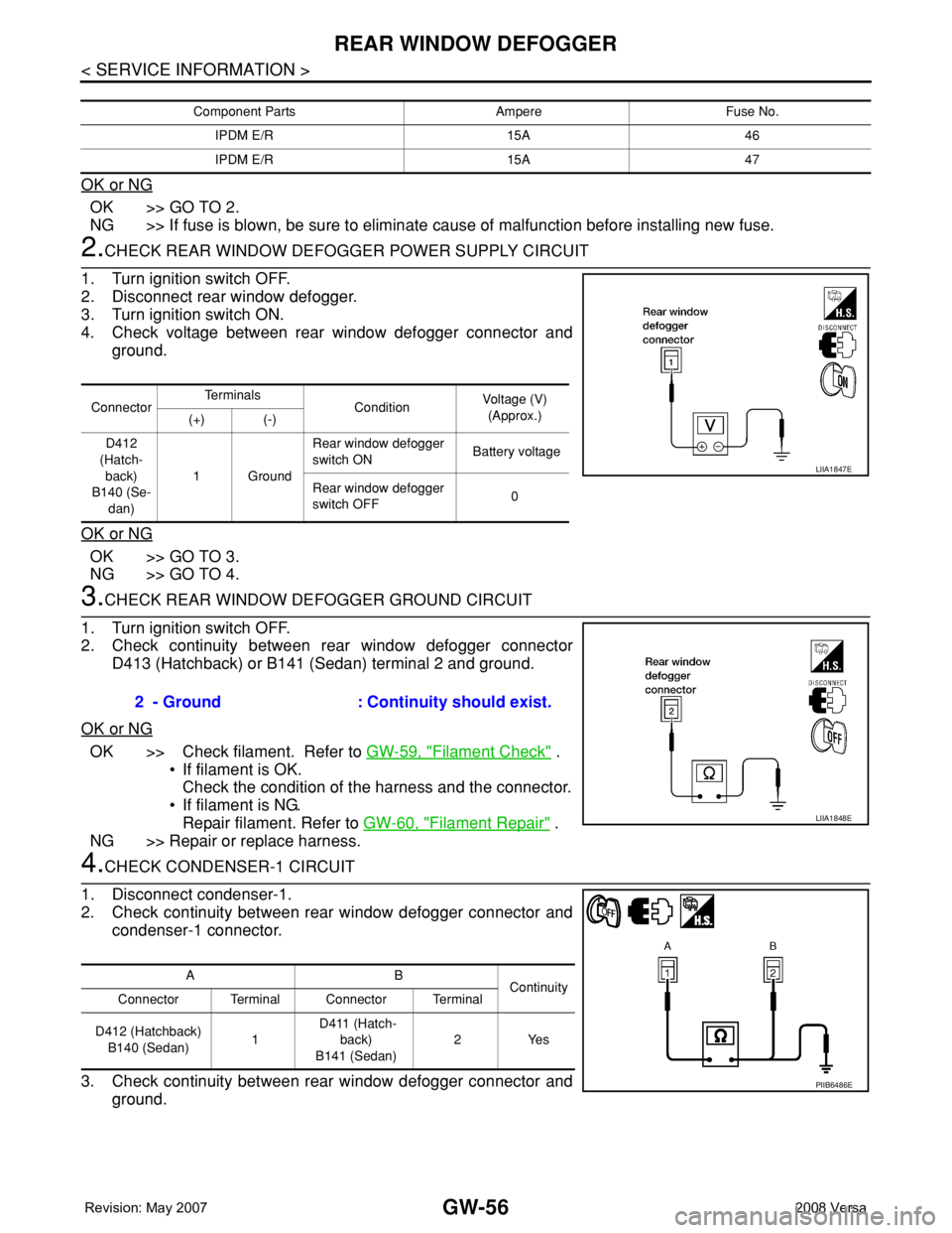
4. Check voltage between rear window defogger connector and
ground.
OK or NG
OK >> GO TO 3.
NG >> GO TO 4.
3.CHECK REAR WINDOW DEFOGGER GROUND CIRCUIT
1. Turn ignition switch OFF.
2. Check continuity between rear window defogger connector
D413 (Hatchback) or B141 (Sedan) terminal 2 and ground.
OK or NG
OK >> Check filament. Refer to GW-59, "Filament Check" .
• If filament is OK.
Check the condition of the harness and the connector.
• If filament is NG.
Repair filament. Refer to GW-60, "
Filament Repair" .
NG >> Repair or replace harness.
4.CHECK CONDENSER-1 CIRCUIT
1. Disconnect condenser-1.
2. Check continuity between rear window defogger connector and
condenser-1 connector.
3. Check continuity between rear window defogger connector and
ground.
Component Parts Ampere Fuse No.
IPDM E/R 15A 46
IPDM E/R 15A 47
ConnectorTe r m i n a l s
ConditionVoltage (V)
(Approx.)
(+) (-)
D412
(Hatch-
back)
B140 (Se-
dan)1GroundRear window defogger
switch ON Battery voltage
Rear window defogger
switch OFF0
LIIA1847E
2 - Ground : Continuity should exist.
LIIA1848E
AB
Continuity
Connector Terminal Connector Terminal
D412 (Hatchback)
B140 (Sedan)1 D411 (Hatch-
back)
B141 (Sedan)2Yes
PIIB6486E
Page 1959 of 2771
GW-58
< SERVICE INFORMATION >
REAR WINDOW DEFOGGER
OK or NG
OK >> Check condition of harness and connector.
NG >> Replace IPDM E/R. Refer to PG-26, "
Removal and Installation of IPDM E/R" .
Door Mirror Defogger Circuit InspectionINFOID:0000000001704178
1.CHECK FUSE
Check if the following fuse in the fuse block (J/B) is blown.
OK or NG
OK >> GO TO 2.
NG >> If fuse is blown, be sure to eliminate cause of malfunction before installing new fuse.
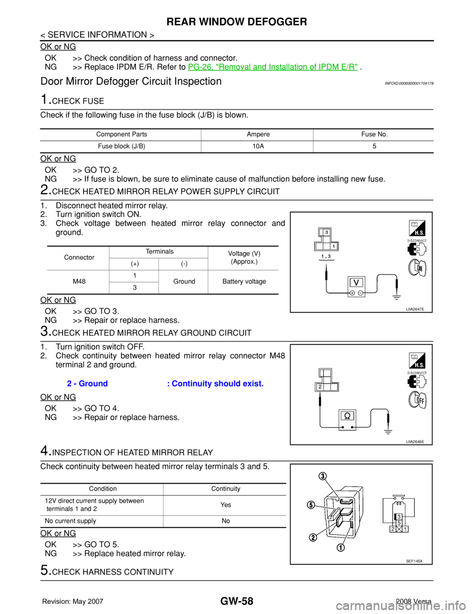
2.CHECK HEATED MIRROR RELAY POWER SUPPLY CIRCUIT
1. Disconnect heated mirror relay.
2. Turn ignition switch ON.
3. Check voltage between heated mirror relay connector and
ground.
OK or NG
OK >> GO TO 3.
NG >> Repair or replace harness.
3.CHECK HEATED MIRROR RELAY GROUND CIRCUIT
1. Turn ignition switch OFF.
2. Check continuity between heated mirror relay connector M48
terminal 2 and ground.
OK or NG
OK >> GO TO 4.
NG >> Repair or replace harness.
4.INSPECTION OF HEATED MIRROR RELAY
Check continuity between heated mirror relay terminals 3 and 5.
OK or NG
OK >> GO TO 5.
NG >> Replace heated mirror relay.
5.CHECK HARNESS CONTINUITY
Component Parts Ampere Fuse No.
Fuse block (J/B) 10A 5
ConnectorTe r m i n a l s
Voltage (V)
(Approx.)
(+) (-)
M481
Ground Battery voltage
3
LIIA2647E
2 - Ground : Continuity should exist.
LIIA2646E
Condition Continuity
12V direct current supply between
terminals 1 and 2Ye s
No current supply No
SEF145X
Page 1965 of 2771
GW-64
< SERVICE INFORMATION >
DOOR MIRROR
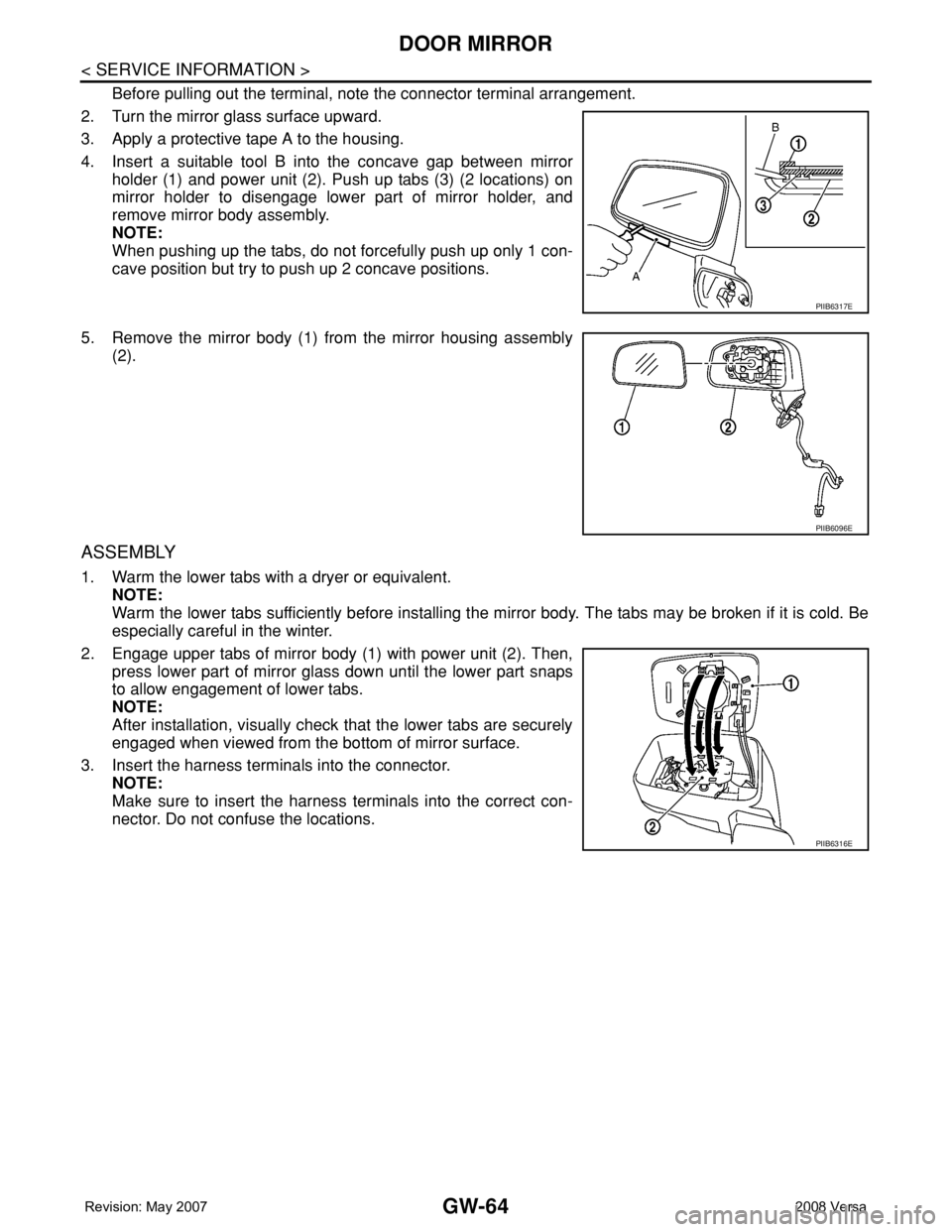
Before pulling out the terminal, note the connector terminal arrangement.
2. Turn the mirror glass surface upward.
3. Apply a protective tape A to the housing.
4. Insert a suitable tool B into the concave gap between mirror
holder (1) and power unit (2). Push up tabs (3) (2 locations) on
mirror holder to disengage lower part of mirror holder, and
remove mirror body assembly.
NOTE:
When pushing up the tabs, do not forcefully push up only 1 con-
cave position but try to push up 2 concave positions.
5. Remove the mirror body (1) from the mirror housing assembly
(2).
ASSEMBLY
1. Warm the lower tabs with a dryer or equivalent.
NOTE:
Warm the lower tabs sufficiently before installing the mirror body. The tabs may be broken if it is cold. Be
especially careful in the winter.
2. Engage upper tabs of mirror body (1) with power unit (2). Then,
press lower part of mirror glass down until the lower part snaps
to allow engagement of lower tabs.
NOTE:
After installation, visually check that the lower tabs are securely
engaged when viewed from the bottom of mirror surface.
3. Insert the harness terminals into the connector.
NOTE:
Make sure to insert the harness terminals into the correct con-
nector. Do not confuse the locations.
PIIB6317E
PIIB6096E
PIIB6316E
Page 1977 of 2771
INSTRUMENT PANEL ASSEMBLY
IP-11
< ON-VEHICLE REPAIR >
C
D
E
F
G
H
J
K
L
MA
B
IP
N
O
P
Removal and InstallationINFOID:0000000001704252
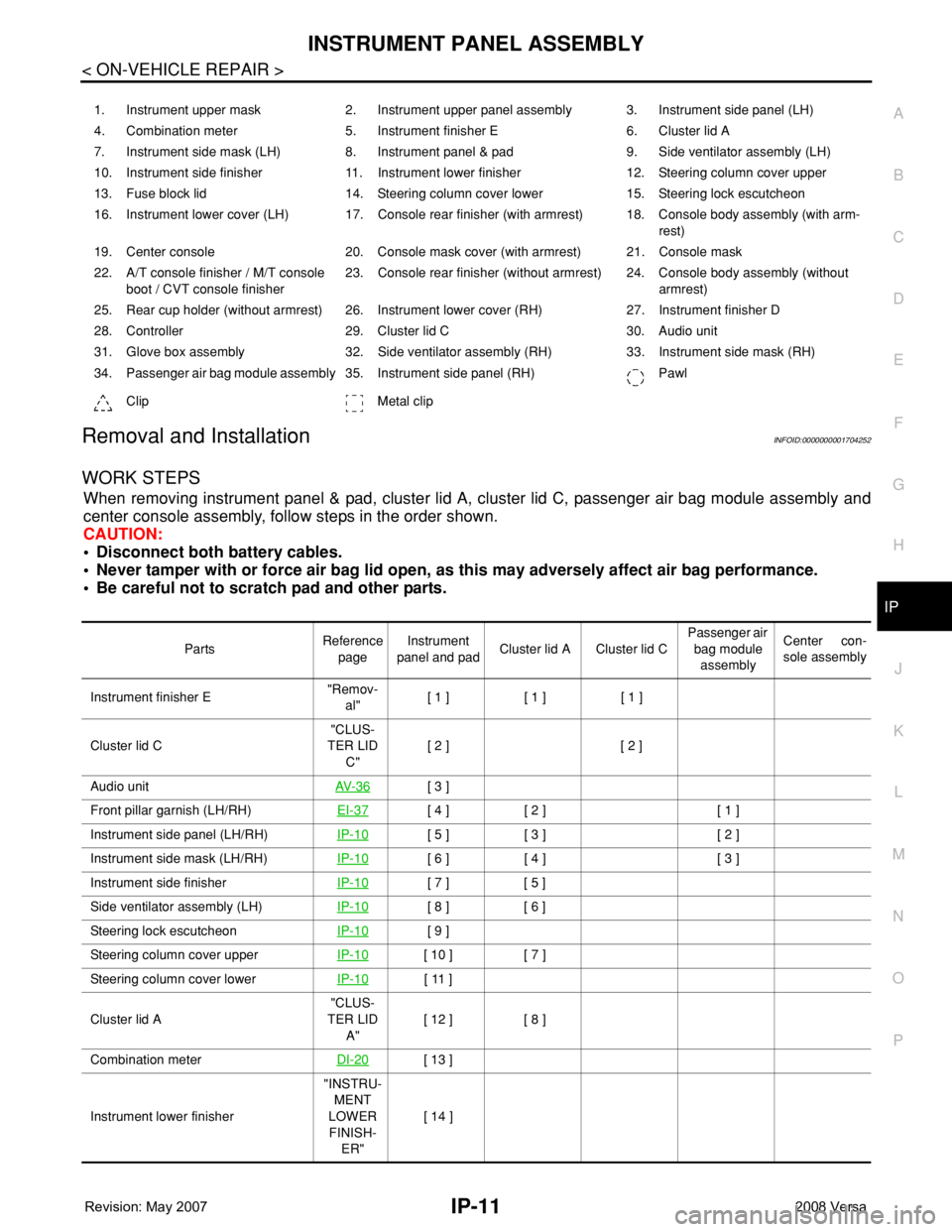
WORK STEPS
When removing instrument panel & pad, cluster lid A, cluster lid C, passenger air bag module assembly and
center console assembly, follow steps in the order shown.
CAUTION:
• Disconnect both battery cables.
• Never tamper with or force air bag lid open, as this may adversely affect air bag performance.
• Be careful not to scratch pad and other parts.
1. Instrument upper mask 2. Instrument upper panel assembly 3. Instrument side panel (LH)
4. Combination meter 5. Instrument finisher E 6. Cluster lid A
7. Instrument side mask (LH) 8. Instrument panel & pad 9. Side ventilator assembly (LH)
10. Instrument side finisher 11. Instrument lower finisher 12. Steering column cover upper
13. Fuse block lid 14. Steering column cover lower 15. Steering lock escutcheon
16. Instrument lower cover (LH) 17. Console rear finisher (with armrest) 18. Console body assembly (with arm-
rest)
19. Center console 20. Console mask cover (with armrest) 21. Console mask
22. A/T console finisher / M/T console
boot / CVT console finisher23. Console rear finisher (without armrest) 24. Console body assembly (without
armrest)
25. Rear cup holder (without armrest) 26. Instrument lower cover (RH) 27. Instrument finisher D
28. Controller 29. Cluster lid C 30. Audio unit
31. Glove box assembly 32. Side ventilator assembly (RH) 33. Instrument side mask (RH)
34. Passenger air bag module assembly 35. Instrument side panel (RH) Pawl
Clip Metal clip
PartsReference
pageInstrument
panel and padCluster lid A Cluster lid C Passenger air
bag module
assemblyCenter con-
sole assembly
Instrument finisher E"Remov-
al"[ 1 ] [ 1 ] [ 1 ]
Cluster lid C"CLUS-
TER LID
C"[ 2 ] [ 2 ]
Audio unitAV- 3 6
[ 3 ]
Front pillar garnish (LH/RH)EI-37
[ 4 ] [ 2 ] [ 1 ]
Instrument side panel (LH/RH)IP-10
[ 5 ] [ 3 ] [ 2 ]
Instrument side mask (LH/RH)IP-10
[ 6 ] [ 4 ] [ 3 ]
Instrument side finisherIP-10
[ 7 ] [ 5 ]
Side ventilator assembly (LH)IP-10
[ 8 ] [ 6 ]
Steering lock escutcheonIP-10
[ 9 ]
Steering column cover upperIP-10
[ 10 ] [ 7 ]
Steering column cover lowerIP-10
[ 11 ]
Cluster lid A"CLUS-
TER LID
A"[ 12 ] [ 8 ]
Combination meterDI-20
[ 13 ]
Instrument lower finisher"INSTRU-
MENT
LOWER
FINISH-
ER"[ 14 ]
Page 1978 of 2771
![NISSAN TIIDA 2008 Service Repair Manual IP-12
< ON-VEHICLE REPAIR >
INSTRUMENT PANEL ASSEMBLY
[ ]: Number indicates step in removal procedures.
INSTRUMENT PANEL ASSEMBLY
Removal
1. Pull instrument finisher E backward by approximately 30
deg NISSAN TIIDA 2008 Service Repair Manual IP-12
< ON-VEHICLE REPAIR >
INSTRUMENT PANEL ASSEMBLY
[ ]: Number indicates step in removal procedures.
INSTRUMENT PANEL ASSEMBLY
Removal
1. Pull instrument finisher E backward by approximately 30
deg](/manual-img/5/57399/w960_57399-1977.png)
IP-12
< ON-VEHICLE REPAIR >
INSTRUMENT PANEL ASSEMBLY
[ ]: Number indicates step in removal procedures.
INSTRUMENT PANEL ASSEMBLY
Removal
1. Pull instrument finisher E backward by approximately 30
degrees while disengaging the instrument finisher E metal clips
and pawl.
Glove box assembly"GLOVE
BOX AS-
SEMBLY"[ 15 ]
Side ventilator assembly (RH)IP-10
[ 16 ] [ 4 ]
Passenger air bag module assemblySRS-38
[ 17 ] [ 5 ]
Instrument upper maskIP-10
[ 18 ]
Instrument finisher DIP-10
[ 19 ]
Controller MTC-55
[ 20 ]
Instrument upper panel assembly IP-10
[ 21 ]
Console mask"Remov-
al"[ 22 ] [ 1 ]
CVT, A/T console finisherIP-23
[ 23 ] [ 2 ]
M/T console bootIP-23
[ 23 ] [ 2 ]
Console rear finisherIP-23
[ 24 ] [ 3 ]
Console mask cover (with arm rest)IP-23
[ 25 ] [ 4 ]
Rear cup holder (without arm rest)IP-23
[ 25 ] [ 4 ]
Console body assemblyIP-23
[ 26 ] [ 5 ]
Instrument lower cover (LH/RH)"INSTRU-
MENT
LOWER
FINISH-
ER"[ 27 ] [ 6 ]
Center console assembly"CEN-
TER
CON-
SOLE AS-
SEMBLY"[ 28 ] [ 7 ]
Fuse block lidIP-10
[ 29 ]
Lighting and turn signal switchLT- 6 0
[ 30 ]
Wiper & washer switchWW-22
[ 31 ]
Instrument panel & padIP-10
[ 32 ] PartsReference
pageInstrument
panel and padCluster lid A Cluster lid C Passenger air
bag module
assemblyCenter con-
sole assembly
WIIA1224E
Page 1981 of 2771
INSTRUMENT PANEL ASSEMBLY
IP-15
< ON-VEHICLE REPAIR >
C
D
E
F
G
H
J
K
L
MA
B
IP
N
O
P
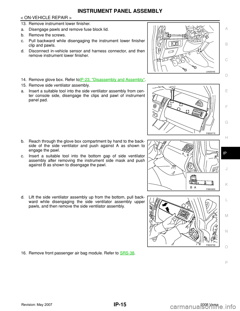
13. Remove instrument lower finisher.
a. Disengage pawls and remove fuse block lid.
b. Remove the screws.
c. Pull backward while disengaging the instrument lower finisher
clip and pawls.
d. Disconnect in-vehicle sensor and harness connector, and then
remove instrument lower finisher.
14. Remove glove box. Refer toIP-23, "
Disassembly and Assembly".
15. Remove side ventilator assembly.
a. Insert a suitable tool into the side ventilator assembly from cen-
ter console side, disengage the clips and pawl of instrument
panel pad.
b. Reach through the glove box compartment by hand to the back-
side of the side ventilator and push against A as shown to
engage the pawl.
c. Insert a suitable tool into the bottom gap of side ventilator
assembly after removing the instrument side mask and push
against B as shown to disengage the pawl.
d. Lift the side ventilator assembly up from the bottom, pull back-
ward while disengaging the side ventilator assembly upper
pawls, and then remove the side ventilator assembly.
16. Remove front passenger air bag module. Refer to SRS-38
.
LIIA2544E
PIIB3977E
PIIB6385E
PIIB3979E
Page 2000 of 2771
![NISSAN TIIDA 2008 Service Repair Manual TROUBLE DIAGNOSIS
LAN-9
< FUNCTION DIAGNOSIS >[CAN FUNDAMENTAL]
C
D
E
F
G
H
I
J
L
MA
B
LAN
N
O
P
TROUBLE DIAGNOSIS
Condition of Error DetectionINFOID:0000000001711205
“U1000” or “U1001” is ind NISSAN TIIDA 2008 Service Repair Manual TROUBLE DIAGNOSIS
LAN-9
< FUNCTION DIAGNOSIS >[CAN FUNDAMENTAL]
C
D
E
F
G
H
I
J
L
MA
B
LAN
N
O
P
TROUBLE DIAGNOSIS
Condition of Error DetectionINFOID:0000000001711205
“U1000” or “U1001” is ind](/manual-img/5/57399/w960_57399-1999.png)
TROUBLE DIAGNOSIS
LAN-9
< FUNCTION DIAGNOSIS >[CAN FUNDAMENTAL]
C
D
E
F
G
H
I
J
L
MA
B
LAN
N
O
P
TROUBLE DIAGNOSIS
Condition of Error DetectionINFOID:0000000001711205
“U1000” or “U1001” is indicated on SELF-DIAG RESULTS on CONSULT-III if CAN communication signal is
not transmitted or received between units for 2 seconds or more.
CAN COMMUNICATION SYSTEM ERROR
• CAN communication line open (CAN-H, CAN-L, or both)
• CAN communication line short (ground, between CAN communication lines, other harnesses)
• Error of CAN communication control circuit of the unit connected to CAN communication line
WHEN “U1000” OR “U1001” IS INDICATED EVEN THOUGH CAN COMMUNICATION SYSTEM IS
NORMAL
• Removal/installation of parts: Error may be detected when removing and installing CAN communication unit
and related parts while turning the ignition switch ON. (A DTC except for CAN communication may be
detected.)
• Fuse blown out (removed): CAN communication of the unit may cease.
• Voltage drop: Error may be detected if voltage drops due to discharged battery when turning the ignition
switch ON (Depending on the control unit which carries out CAN communication).
• Error may be detected if the power supply circuit of the control unit, which carries out CAN communication,
malfunctions (Depending on the control unit which carries out CAN communication).
• Error may be detected if reprogramming is not completed normally.
NOTE:
CAN communication system is normal if “U1000” or “U1001” is indicated on SELF-DIAG RESULTS of CON-
SULT-III under the above conditions. Erase the memory of the self-diagnosis of each unit.
Symptom When Error Occurs in CAN Communication SystemINFOID:0000000001711206
In CAN communication system, multiple units mutually transmit and receive signals. Each unit cannot transmit
and receive signals if any error occurs on CAN communication line. Under this condition, multiple control units
related to the root cause malfunction or go into fail-safe mode.
ERROR EXAMPLE
NOTE:
• Each vehicle differs in symptom of each unit under fail-safe mode and CAN communication line wiring.
• Refer to LAN-20, "
Abbreviation List" for the unit abbreviation.
Example: TCM branch line open circuit
SKIB8738E
Unit name Symptom
ECM Engine torque limiting is affected, and shift harshness increases.
BCM Reverse warning chime does not sound.