2008 NISSAN TIIDA fuse
[x] Cancel search: fusePage 1868 of 2771
HOW TO USE THIS MANUAL
GI-17
< SERVICE INFORMATION >
C
D
E
F
G
H
I
J
K
L
MB
GI
N
O
P
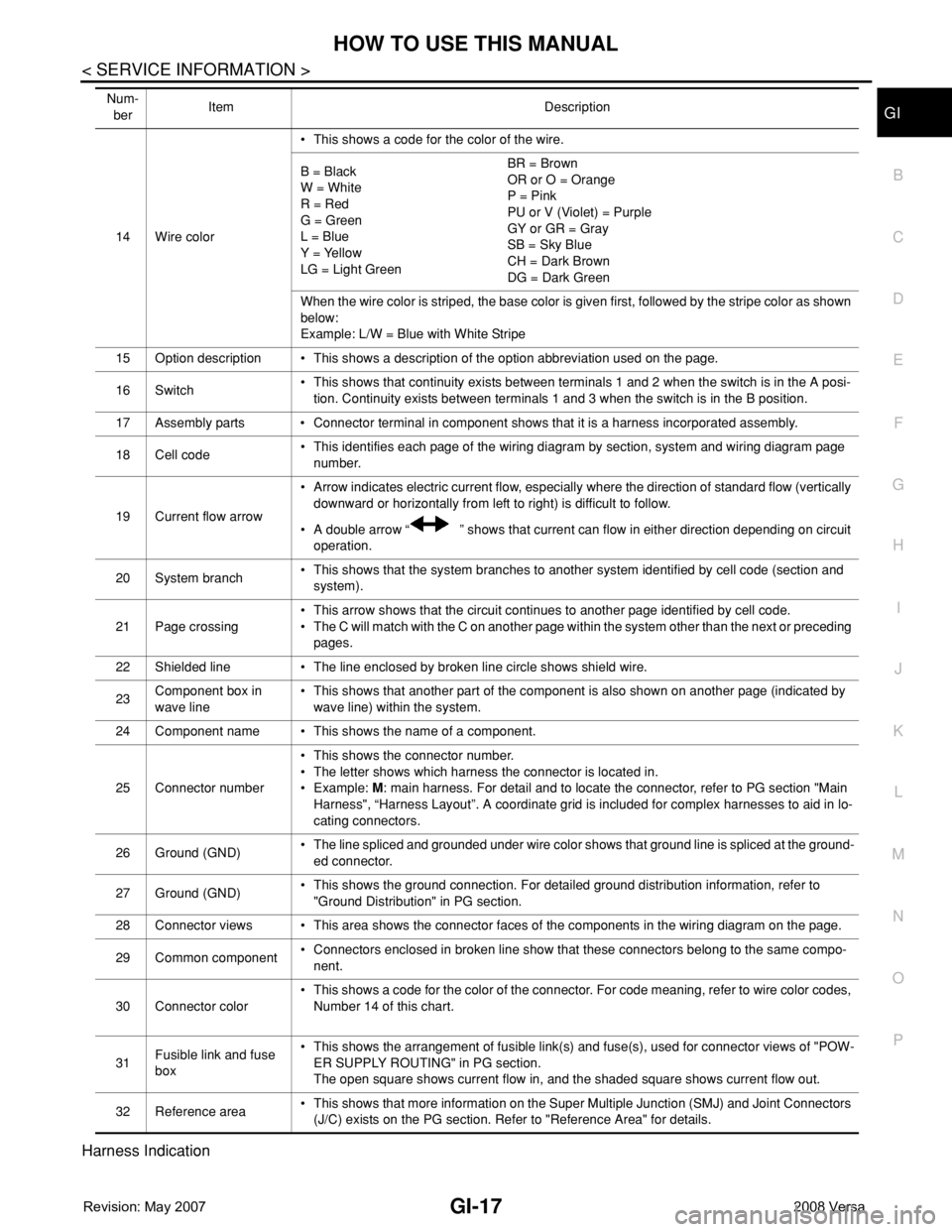
Harness Indication
14 Wire color• This shows a code for the color of the wire.
B = Black
W = White
R = Red
G = Green
L = Blue
Y = Yellow
LG = Light GreenBR = Brown
OR or O = Orange
P = Pink
PU or V (Violet) = Purple
GY or GR = Gray
SB = Sky Blue
CH = Dark Brown
DG = Dark Green
When the wire color is striped, the base color is given first, followed by the stripe color as shown
below:
Example: L/W = Blue with White Stripe
15 Option description • This shows a description of the option abbreviation used on the page.
16 Switch• This shows that continuity exists between terminals 1 and 2 when the switch is in the A posi-
tion. Continuity exists between terminals 1 and 3 when the switch is in the B position.
17 Assembly parts • Connector terminal in component shows that it is a harness incorporated assembly.
18 Cell code• This identifies each page of the wiring diagram by section, system and wiring diagram page
number.
19 Current flow arrow• Arrow indicates electric current flow, especially where the direction of standard flow (vertically
downward or horizontally from left to right) is difficult to follow.
• A double arrow “ ” shows that current can flow in either direction depending on circuit
operation.
20 System branch• This shows that the system branches to another system identified by cell code (section and
system).
21 Page crossing• This arrow shows that the circuit continues to another page identified by cell code.
• The C will match with the C on another page within the system other than the next or preceding
pages.
22 Shielded line • The line enclosed by broken line circle shows shield wire.
23Component box in
wave line• This shows that another part of the component is also shown on another page (indicated by
wave line) within the system.
24 Component name • This shows the name of a component.
25 Connector number• This shows the connector number.
• The letter shows which harness the connector is located in.
•Example: M: main harness. For detail and to locate the connector, refer to PG section "Main
Harness", “Harness Layout”. A coordinate grid is included for complex harnesses to aid in lo-
cating connectors.
26 Ground (GND)• The line spliced and grounded under wire color shows that ground line is spliced at the ground-
ed connector.
27 Ground (GND)• This shows the ground connection. For detailed ground distribution information, refer to
"Ground Distribution" in PG section.
28 Connector views • This area shows the connector faces of the components in the wiring diagram on the page.
29 Common component• Connectors enclosed in broken line show that these connectors belong to the same compo-
nent.
30 Connector color• This shows a code for the color of the connector. For code meaning, refer to wire color codes,
Number 14 of this chart.
31Fusible link and fuse
box• This shows the arrangement of fusible link(s) and fuse(s), used for connector views of "POW-
ER SUPPLY ROUTING" in PG section.
The open square shows current flow in, and the shaded square shows current flow out.
32 Reference area• This shows that more information on the Super Multiple Junction (SMJ) and Joint Connectors
(J/C) exists on the PG section. Refer to "Reference Area" for details. Num-
berItem Description
Page 1879 of 2771
GI-28
< SERVICE INFORMATION >
SERVICE INFORMATION FOR ELECTRICAL INCIDENT
ough understanding of system operation. Then you will be able to use the appropriate equipment and follow
the correct test procedure.
You may have to simulate vehicle vibrations while testing electrical components. Gently shake the wiring har-
ness or electrical component to do this.
NOTE:
Refer to “How to Check Terminal” to probe or check terminal.
Testing for “Opens” in the Circuit
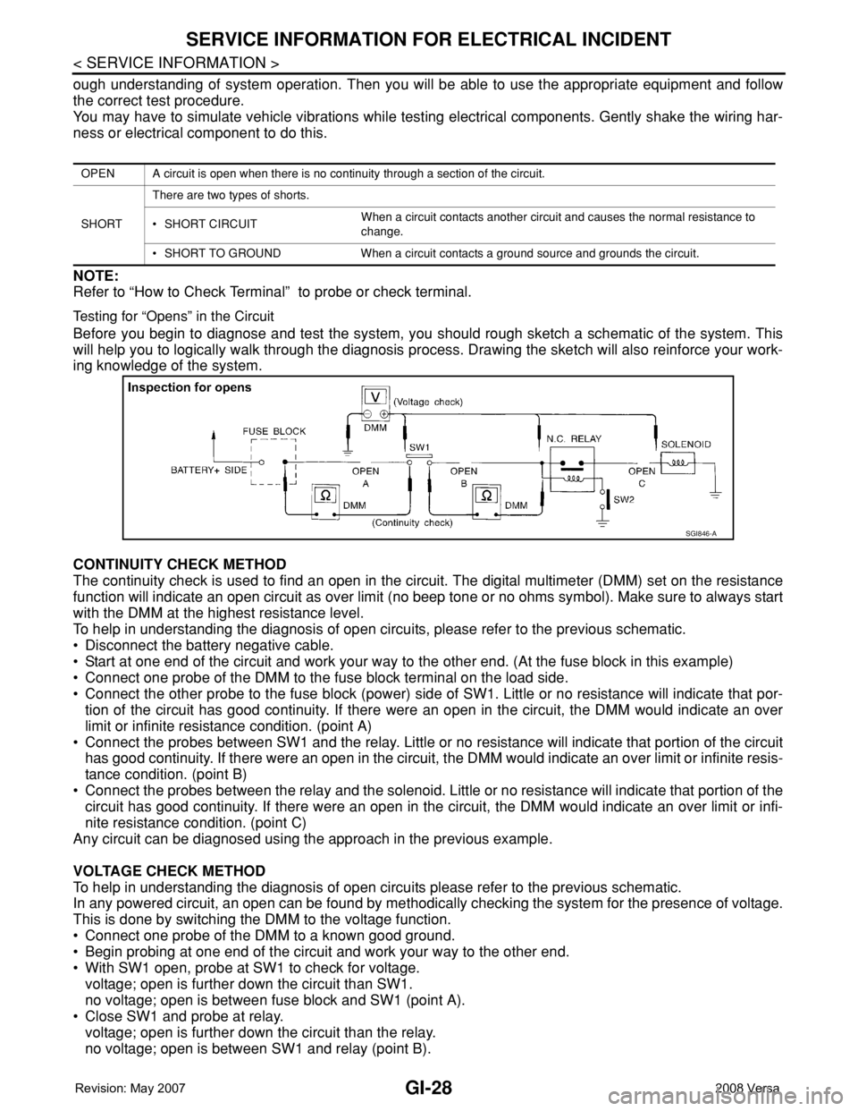
Before you begin to diagnose and test the system, you should rough sketch a schematic of the system. This
will help you to logically walk through the diagnosis process. Drawing the sketch will also reinforce your work-
ing knowledge of the system.
CONTINUITY CHECK METHOD
The continuity check is used to find an open in the circuit. The digital multimeter (DMM) set on the resistance
function will indicate an open circuit as over limit (no beep tone or no ohms symbol). Make sure to always start
with the DMM at the highest resistance level.
To help in understanding the diagnosis of open circuits, please refer to the previous schematic.
• Disconnect the battery negative cable.
• Start at one end of the circuit and work your way to the other end. (At the fuse block in this example)
• Connect one probe of the DMM to the fuse block terminal on the load side.
• Connect the other probe to the fuse block (power) side of SW1. Little or no resistance will indicate that por-
tion of the circuit has good continuity. If there were an open in the circuit, the DMM would indicate an over
limit or infinite resistance condition. (point A)
• Connect the probes between SW1 and the relay. Little or no resistance will indicate that portion of the circuit
has good continuity. If there were an open in the circuit, the DMM would indicate an over limit or infinite resis-
tance condition. (point B)
• Connect the probes between the relay and the solenoid. Little or no resistance will indicate that portion of the
circuit has good continuity. If there were an open in the circuit, the DMM would indicate an over limit or infi-
nite resistance condition. (point C)
Any circuit can be diagnosed using the approach in the previous example.
VOLTAGE CHECK METHOD
To help in understanding the diagnosis of open circuits please refer to the previous schematic.
In any powered circuit, an open can be found by methodically checking the system for the presence of voltage.
This is done by switching the DMM to the voltage function.
• Connect one probe of the DMM to a known good ground.
• Begin probing at one end of the circuit and work your way to the other end.
• With SW1 open, probe at SW1 to check for voltage.
voltage; open is further down the circuit than SW1.
no voltage; open is between fuse block and SW1 (point A).
• Close SW1 and probe at relay.
voltage; open is further down the circuit than the relay.
no voltage; open is between SW1 and relay (point B).
OPEN A circuit is open when there is no continuity through a section of the circuit.
SHORTThere are two types of shorts.
• SHORT CIRCUITWhen a circuit contacts another circuit and causes the normal resistance to
change.
• SHORT TO GROUND When a circuit contacts a ground source and grounds the circuit.
SGI846-A
Page 1880 of 2771
SERVICE INFORMATION FOR ELECTRICAL INCIDENT
GI-29
< SERVICE INFORMATION >
C
D
E
F
G
H
I
J
K
L
MB
GI
N
O
P
• Close the relay and probe at the solenoid.
voltage; open is further down the circuit than the solenoid.
no voltage; open is between relay and solenoid (point C).
Any powered circuit can be diagnosed using the approach in the previous example.
Testing for “Shorts” in the Circuit
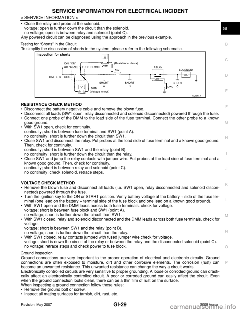
To simplify the discussion of shorts in the system, please refer to the following schematic.
RESISTANCE CHECK METHOD
• Disconnect the battery negative cable and remove the blown fuse.
• Disconnect all loads (SW1 open, relay disconnected and solenoid disconnected) powered through the fuse.
• Connect one probe of the DMM to the load side of the fuse terminal. Connect the other probe to a known
good ground.
• With SW1 open, check for continuity.
continuity; short is between fuse terminal and SW1 (point A).
no continuity; short is further down the circuit than SW1.
• Close SW1 and disconnect the relay. Put probes at the load side of fuse terminal and a known good ground.
Then, check for continuity.
continuity; short is between SW1 and the relay (point B).
no continuity; short is further down the circuit than the relay.
• Close SW1 and jump the relay contacts with jumper wire. Put probes at the load side of fuse terminal and a
known good ground. Then, check for continuity.
continuity; short is between relay and solenoid (point C).
no continuity; check solenoid, retrace steps.
VOLTAGE CHECK METHOD
• Remove the blown fuse and disconnect all loads (i.e. SW1 open, relay disconnected and solenoid discon-
nected) powered through the fuse.
• Turn the ignition key to the ON or START position. Verify battery voltage at the battery + side of the fuse ter-
minal (one lead on the battery + terminal side of the fuse block and one lead on a known good ground).
• With SW1 open and the DMM leads across both fuse terminals, check for voltage.
voltage; short is between fuse block and SW1 (point A).
no voltage; short is further down the circuit than SW1.
• With SW1 closed, relay and solenoid disconnected and the DMM leads across both fuse terminals, check for
voltage.
voltage; short is between SW1 and the relay (point B).
no voltage; short is further down the circuit than the relay.
• With SW1 closed, relay contacts jumped with fused jumper wire check for voltage.
voltage; short is down the circuit of the relay or between the relay and the disconnected solenoid (point C).
no voltage; retrace steps and check power to fuse block.
Ground Inspection
Ground connections are very important to the proper operation of electrical and electronic circuits. Ground
connections are often exposed to moisture, dirt and other corrosive elements. The corrosion (rust) can
become an unwanted resistance. This unwanted resistance can change the way a circuit works.
Electronically controlled circuits are very sensitive to proper grounding. A loose or corroded ground can drasti-
cally affect an electronically controlled circuit. A poor or corroded ground can easily affect the circuit. Even
when the ground connection looks clean, there can be a thin film of rust on the surface.
When inspecting a ground connection follow these rules:
• Remove the ground bolt or screw.
• Inspect all mating surfaces for tarnish, dirt, rust, etc.
SGI847-A
Page 1919 of 2771
GW-18
< SERVICE INFORMATION >
POWER WINDOW SYSTEM
POWER WINDOW SYSTEM
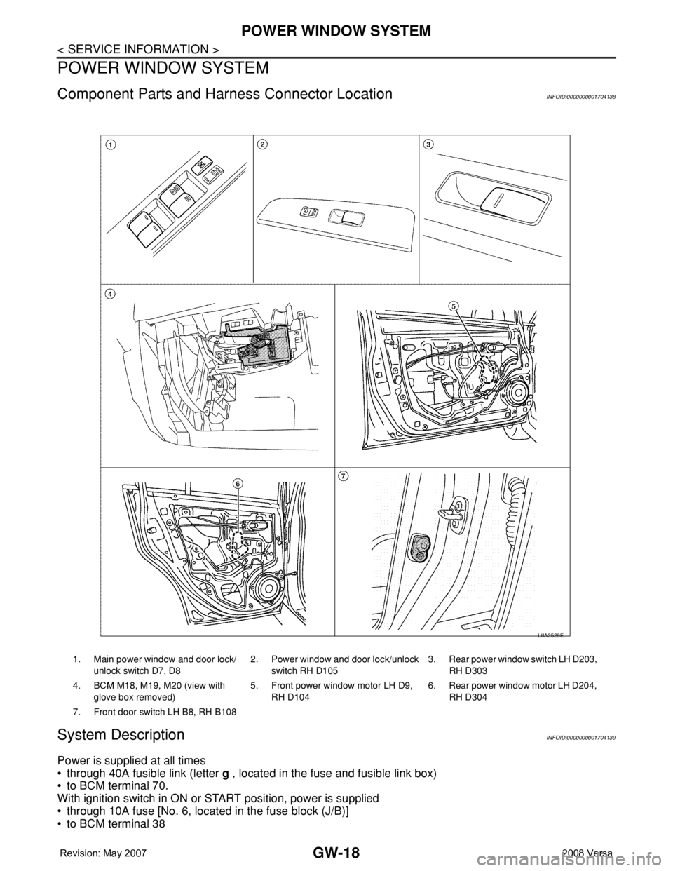
Component Parts and Harness Connector LocationINFOID:0000000001704138
System DescriptionINFOID:0000000001704139
Power is supplied at all times
• through 40A fusible link (letter g , located in the fuse and fusible link box)
• to BCM terminal 70.
With ignition switch in ON or START position, power is supplied
• through 10A fuse [No. 6, located in the fuse block (J/B)]
• to BCM terminal 38
1. Main power window and door lock/
unlock switch D7, D82. Power window and door lock/unlock
switch RH D1053. Rear power window switch LH D203,
RH D303
4. BCM M18, M19, M20 (view with
glove box removed)5. Front power window motor LH D9,
RH D1046. Rear power window motor LH D204,
RH D304
7. Front door switch LH B8, RH B108
LIIA2529E
Page 1920 of 2771

POWER WINDOW SYSTEM
GW-19
< SERVICE INFORMATION >
C
D
E
F
G
H
J
K
L
MA
B
GW
N
O
P
• through BCM terminal 68
• to main power window and door lock/unlock switch terminal 10
• to power window and door lock/unlock switch RH terminal 8 and
• to rear power window switches LH and RH terminal 1.
Ground is supplied
• to BCM terminal 67
• to main power window and door lock/unlock switch terminal 17 and
• to power window and door lock/unlock switch RH terminal 3
• through body grounds M57 and M61.
With ignition switch in ACC or ON position, power is supplied
• through 10A fuse [No. 20, located in the fuse block (J/B)]
• to BCM terminal 11.
MANUAL OPERATION
Front Door LH
WINDOW UP
When the front LH switch in the main power window and door lock/unlock switch is pulled in the up position,
power is supplied
• through main power window and door lock/unlock switch terminal 8
• to front power window motor LH terminal 2.
Ground is supplied
• through main power window and door lock/unlock switch terminal 11
• to front power window motor LH terminal 3.
Then, the motor raises the window until the switch is released.
WINDOW DOWN
When the front LH switch in the main power window and door lock/unlock switch is pressed in the down posi-
tion, power is supplied
• through main power window and door lock/unlock switch terminal 11
• to front power window motor LH terminal 3.
Ground is supplied
• through main power window and door lock/unlock switch terminal 8
• to front power window motor LH terminal 2.
Then, the motor lowers the window until the switch is released.
Front Door RH
POWER WINDOW AND DOOR LOCK/UNLOCK SWITCH RH OPERATION
WINDOW UP
When the power window and door lock/unlock switch RH is pulled in the up position, power is supplied
• through power window and door lock/unlock switch RH terminal 7
• to front power window motor RH terminal 2.
Ground is supplied
• through power window and door lock/unlock switch RH terminal 6
• to front power window motor RH terminal 1.
Then, the motor raises the window until the switch is released.
WINDOW DOWN
When the power window and door lock/unlock switch RH is pressed in the down position, power is supplied
• through power window and door lock/unlock switch RH terminal 6
• to front power window motor RH terminal 1.
Ground is supplied
• through power window and door lock/unlock switch RH terminal 7
• to front power window motor RH terminal 2.
Then, the motor lowers the window until the switch is released.
MAIN POWER WINDOW AND DOOR LOCK/UNLOCK SWITCH OPERATION
WINDOW UP
When the main power window and door lock/unlock switch (front RH) is pulled in the up position, power is sup-
plied
• through main power window and door lock/unlock switch terminal 16
• to power window and door lock/unlock switch RH terminal 12
• through power window and door lock/unlock switch RH terminal 7
• to front power window motor RH terminal 2.
Ground is supplied
Page 1930 of 2771
POWER WINDOW SYSTEM
GW-29
< SERVICE INFORMATION >
C
D
E
F
G
H
J
K
L
MA
B
GW
N
O
P
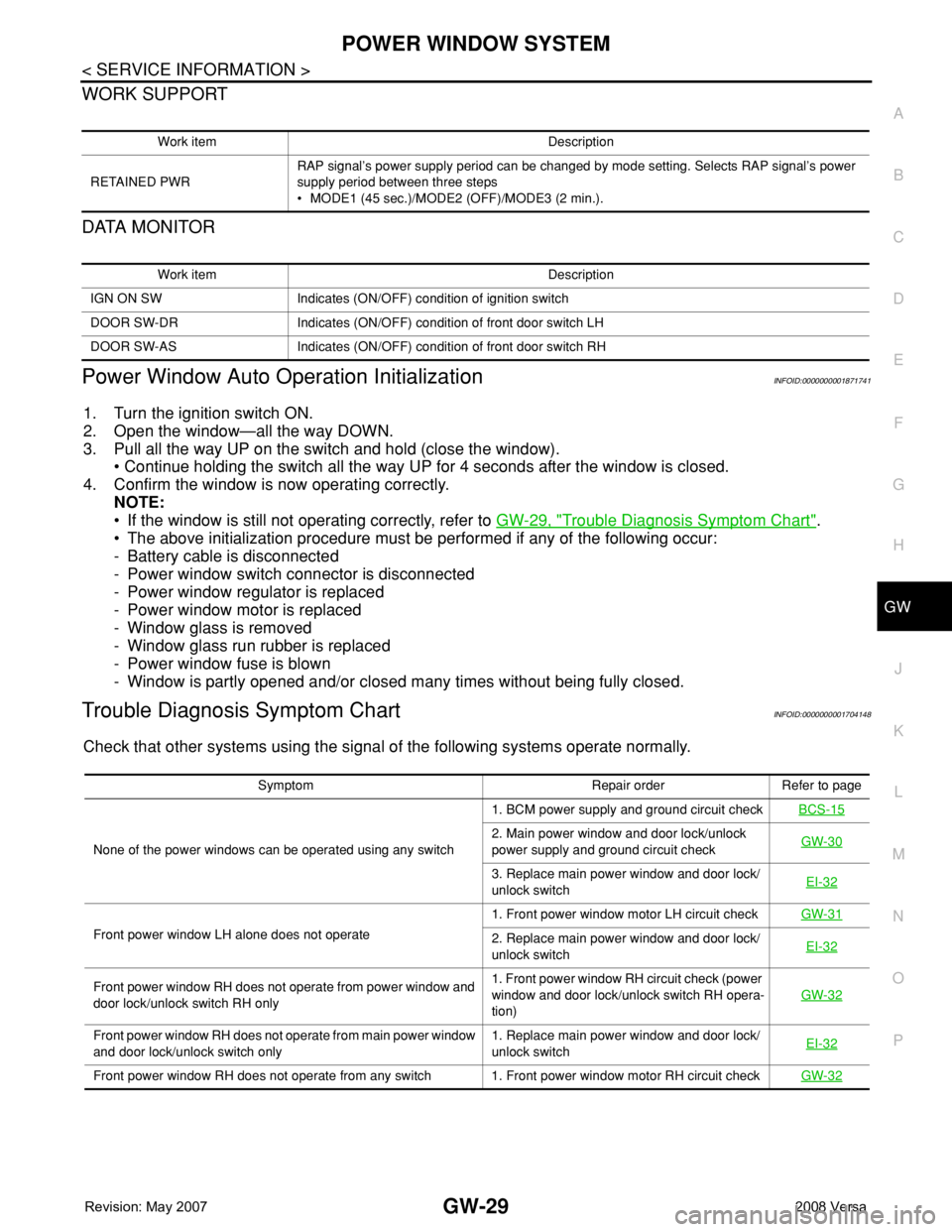
WORK SUPPORT
DATA MONITOR
Power Window Auto Operation InitializationINFOID:0000000001871741
1. Turn the ignition switch ON.
2. Open the window—all the way DOWN.
3. Pull all the way UP on the switch and hold (close the window).
• Continue holding the switch all the way UP for 4 seconds after the window is closed.
4. Confirm the window is now operating correctly.
NOTE:
• If the window is still not operating correctly, refer to GW-29, "
Trouble Diagnosis Symptom Chart".
• The above initialization procedure must be performed if any of the following occur:
- Battery cable is disconnected
- Power window switch connector is disconnected
- Power window regulator is replaced
- Power window motor is replaced
- Window glass is removed
- Window glass run rubber is replaced
- Power window fuse is blown
- Window is partly opened and/or closed many times without being fully closed.
Trouble Diagnosis Symptom ChartINFOID:0000000001704148
Check that other systems using the signal of the following systems operate normally.
Work item Description
RETAINED PWRRAP signal’s power supply period can be changed by mode setting. Selects RAP signal’s power
supply period between three steps
• MODE1 (45 sec.)/MODE2 (OFF)/MODE3 (2 min.).
Work item Description
IGN ON SW Indicates (ON/OFF) condition of ignition switch
DOOR SW-DR Indicates (ON/OFF) condition of front door switch LH
DOOR SW-AS Indicates (ON/OFF) condition of front door switch RH
Symptom Repair order Refer to page
None of the power windows can be operated using any switch1. BCM power supply and ground circuit checkBCS-15
2. Main power window and door lock/unlock
power supply and ground circuit checkGW-30
3. Replace main power window and door lock/
unlock switchEI-32
Front power window LH alone does not operate1. Front power window motor LH circuit checkGW-312. Replace main power window and door lock/
unlock switchEI-32
Front power window RH does not operate from power window and
door lock/unlock switch RH only1. Front power window RH circuit check (power
window and door lock/unlock switch RH opera-
tion)GW-32
Front power window RH does not operate from main power window
and door lock/unlock switch only1. Replace main power window and door lock/
unlock switchEI-32
Front power window RH does not operate from any switch 1. Front power window motor RH circuit checkGW-32
Page 1945 of 2771
GW-44
< SERVICE INFORMATION >
FRONT DOOR GLASS AND REGULATOR
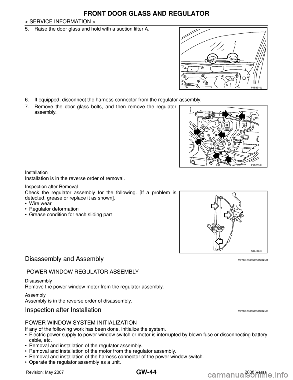
5. Raise the door glass and hold with a suction lifter A.
6. If equipped, disconnect the harness connector from the regulator assembly.
7. Remove the door glass bolts, and then remove the regulator
assembly.
Installation
Installation is in the reverse order of removal.
Inspection after Removal
Check the regulator assembly for the following. [If a problem is
detected, grease or replace it as shown].
• Wire wear
• Regulator deformation
• Grease condition for each sliding part
Disassembly and AssemblyINFOID:0000000001704161
POWER WINDOW REGULATOR ASSEMBLY
Disassembly
Remove the power window motor from the regulator assembly.
Assembly
Assembly is in the reverse order of disassembly.
Inspection after InstallationINFOID:0000000001704162
POWER WINDOW SYSTEM INITIALIZATION
If any of the following work has been done, initialize the system.
• Electric power supply to power window switch or motor is interrupted by blown fuse or disconnecting battery
cable, etc.
• Removal and installation of the regulator assembly.
• Removal and installation of the motor from the regulator assembly.
• Removal and installation of the harness connector of the power window switch.
• Operate the regulator assembly as a unit.
PIIB3510J
PIIB2633J
SIIA1781J
Page 1951 of 2771

GW-50
< SERVICE INFORMATION >
REAR WINDOW DEFOGGER
Power is supplied at all times
• through 15A fuses (No. 46 and 47, located in the IPDM E/R)
• to rear window defogger relay
• through 10A fuse [No. 5 (with heated mirrors), located in the fuse block (J/B)]
• to heated mirror relay terminal 3
• through 40A fusible link (letter g , located in the fuse and fusible link box)
• to BCM terminal 70.
With the ignition switch turned to ON or START position, power is supplied
• through ignition relay
• to rear window defogger relay (located in the IPDM E/R)
• through 10A fuse [No. 6, located in the fuse block (J/B)]
• to BCM terminal 38.
Ground is supplied
• to BCM terminal 67 and
• to front air control terminal 8
• through body grounds M57 and M61
• to IPDM E/R terminals 39 and 59
• through body grounds E15 and E24.
When front air control (rear window defogger switch) is turned to ON, ground is supplied
• to BCM terminal 9
• through front air control terminal 3
• through front air control terminal 8
• through body grounds M57 and M61.
Then rear window defogger switch is illuminated.
Then BCM recognizes that rear window defogger switch is turned to ON.
Then it sends rear window defogger switch signals to IPDM E/R via CAN communication (CAN-H, CAN-L).
When IPDM E/R receives rear window defogger switch signals, ground is supplied
• to rear window defogger relay (located in the IPDM E/R)
• through IPDM E/R terminals 39 and 59
• through body grounds E15 and E24
Then rear window defogger relay is energized.
With power and ground supplied, rear window defogger filaments heat and defog the rear window.
When rear window defogger relay is turned to ON (with heated mirrors), power is supplied
• through heated mirror relay terminal 5
• to door mirror (LH and RH) terminal 1.
Door mirror (LH and RH) is grounded through body grounds M57 and M61.
With power and ground supplied, rear window defogger filaments heat and defog the rear window and door
mirror filaments heat and defog the mirrors.
CAN Communication System DescriptionINFOID:0000000001704168
Refer to LAN-6, "System Description".