2008 NISSAN TIIDA fuse
[x] Cancel search: fusePage 1579 of 2771
DTC P2A00 A/F SENSOR 1
EC-505
< SERVICE INFORMATION >
C
D
E
F
G
H
I
J
K
L
MA
EC
N
P O
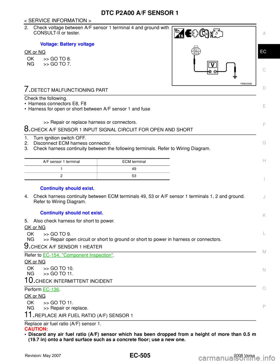
2. Check voltage between A/F sensor 1 terminal 4 and ground with
CONSULT-II or tester.
OK or NG
OK >> GO TO 8.
NG >> GO TO 7.
7.DETECT MALFUNCTIONING PART
Check the following.
• Harness connectors E8, F8
• Harness for open or short between A/F sensor 1 and fuse
>> Repair or replace harness or connectors.
8.CHECK A/F SENSOR 1 INPUT SIGNAL CIRCUIT FOR OPEN AND SHORT
1. Turn ignition switch OFF.
2. Disconnect ECM harness connector.
3. Check harness continuity between the following terminals. Refer to Wiring Diagram.
4. Check harness continuity between ECM terminals 49, 53 or A/F sensor 1 terminals 1, 2 and ground.
Refer to Wiring Diagram.
5. Also check harness for short to power.
OK or NG
OK >> GO TO 9.
NG >> Repair open circuit or short to ground or short to power in harness or connectors.
9.CHECK A/F SENSOR 1 HEATER
Refer to EC-154, "
Component Inspection".
OK or NG
OK >> GO TO 10.
NG >> GO TO 11.
10.CHECK INTERMITTENT INCIDENT
Perform EC-136
.
OK or NG
OK >> GO TO 11.
NG >> Repair or replace.
11 .REPLACE AIR FUEL RATIO (A/F) SENSOR 1
Replace air fuel ratio (A/F) sensor 1.
CAUTION:
• Discard any air fuel ratio (A/F) sensor which has been dropped from a height of more than 0.5 m
(19.7 in) onto a hard surface such as a concrete floor; use a new one. Voltage: Battery voltage
PBIB3308E
A/F sensor 1 terminal ECM terminal
149
253
Continuity should exist.
Continuity should not exist.
Page 1586 of 2771
EC-512
< SERVICE INFORMATION >
ASCD BRAKE SWITCH
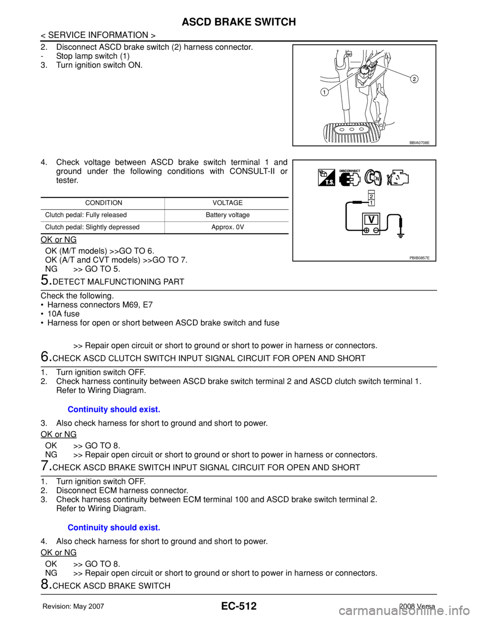
2. Disconnect ASCD brake switch (2) harness connector.
- Stop lamp switch (1)
3. Turn ignition switch ON.
4. Check voltage between ASCD brake switch terminal 1 and
ground under the following conditions with CONSULT-II or
tester.
OK or NG
OK (M/T models) >>GO TO 6.
OK (A/T and CVT models) >>GO TO 7.
NG >> GO TO 5.
5.DETECT MALFUNCTIONING PART
Check the following.
• Harness connectors M69, E7
• 10A fuse
• Harness for open or short between ASCD brake switch and fuse
>> Repair open circuit or short to ground or short to power in harness or connectors.
6.CHECK ASCD CLUTCH SWITCH INPUT SIGNAL CIRCUIT FOR OPEN AND SHORT
1. Turn ignition switch OFF.
2. Check harness continuity between ASCD brake switch terminal 2 and ASCD clutch switch terminal 1.
Refer to Wiring Diagram.
3. Also check harness for short to ground and short to power.
OK or NG
OK >> GO TO 8.
NG >> Repair open circuit or short to ground or short to power in harness or connectors.
7.CHECK ASCD BRAKE SWITCH INPUT SIGNAL CIRCUIT FOR OPEN AND SHORT
1. Turn ignition switch OFF.
2. Disconnect ECM harness connector.
3. Check harness continuity between ECM terminal 100 and ASCD brake switch terminal 2.
Refer to Wiring Diagram.
4. Also check harness for short to ground and short to power.
OK or NG
OK >> GO TO 8.
NG >> Repair open circuit or short to ground or short to power in harness or connectors.
8.CHECK ASCD BRAKE SWITCH
BBIA0708E
CONDITION VOLTAGE
Clutch pedal: Fully released Battery voltage
Clutch pedal: Slightly depressed Approx. 0V
PBIB0857E
Continuity should exist.
Continuity should exist.
Page 1598 of 2771
EC-524
< SERVICE INFORMATION >
FUEL INJECTOR
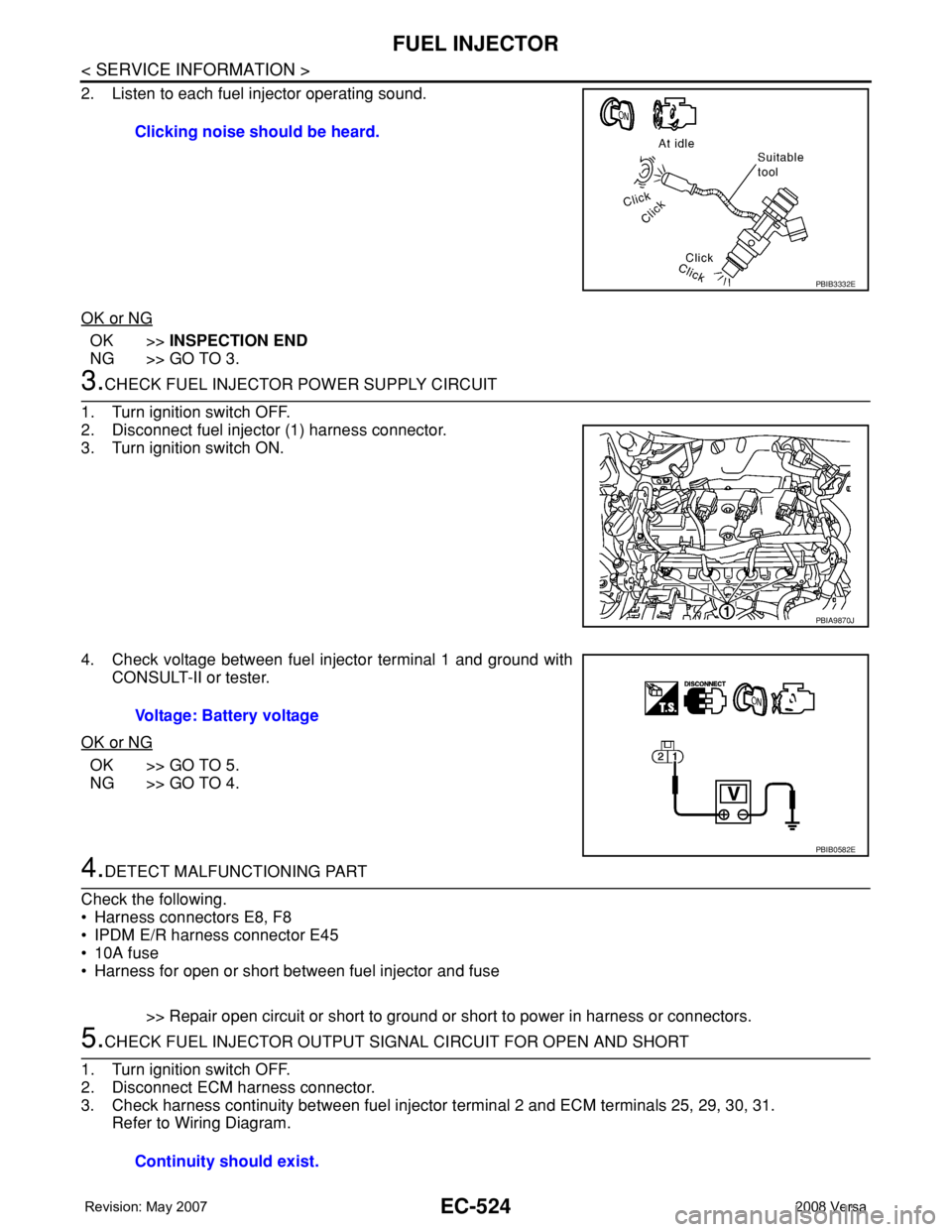
2. Listen to each fuel injector operating sound.
OK or NG
OK >>INSPECTION END
NG >> GO TO 3.
3.CHECK FUEL INJECTOR POWER SUPPLY CIRCUIT
1. Turn ignition switch OFF.
2. Disconnect fuel injector (1) harness connector.
3. Turn ignition switch ON.
4. Check voltage between fuel injector terminal 1 and ground with
CONSULT-II or tester.
OK or NG
OK >> GO TO 5.
NG >> GO TO 4.
4.DETECT MALFUNCTIONING PART
Check the following.
• Harness connectors E8, F8
• IPDM E/R harness connector E45
• 10A fuse
• Harness for open or short between fuel injector and fuse
>> Repair open circuit or short to ground or short to power in harness or connectors.
5.CHECK FUEL INJECTOR OUTPUT SIGNAL CIRCUIT FOR OPEN AND SHORT
1. Turn ignition switch OFF.
2. Disconnect ECM harness connector.
3. Check harness continuity between fuel injector terminal 2 and ECM terminals 25, 29, 30, 31.
Refer to Wiring Diagram.Clicking noise should be heard.
PBIB3332E
PBIA9870J
Voltage: Battery voltage
PBIB0582E
Continuity should exist.
Page 1603 of 2771
FUEL PUMP
EC-529
< SERVICE INFORMATION >
C
D
E
F
G
H
I
J
K
L
MA
EC
N
P O
4.DETECT MALFUNCTIONING PART
Check the following.
• Harness connectors E8, F8
• Harness for open or short between IPDM E/R and ECM
>> Repair open circuit or short to ground or short to power in harness or connectors.
5.CHECK FUEL PUMP POWER SUPPLY CIRCUIT-III
1. Turn ignition switch OFF.
2. Reconnect all harness connectors disconnected.
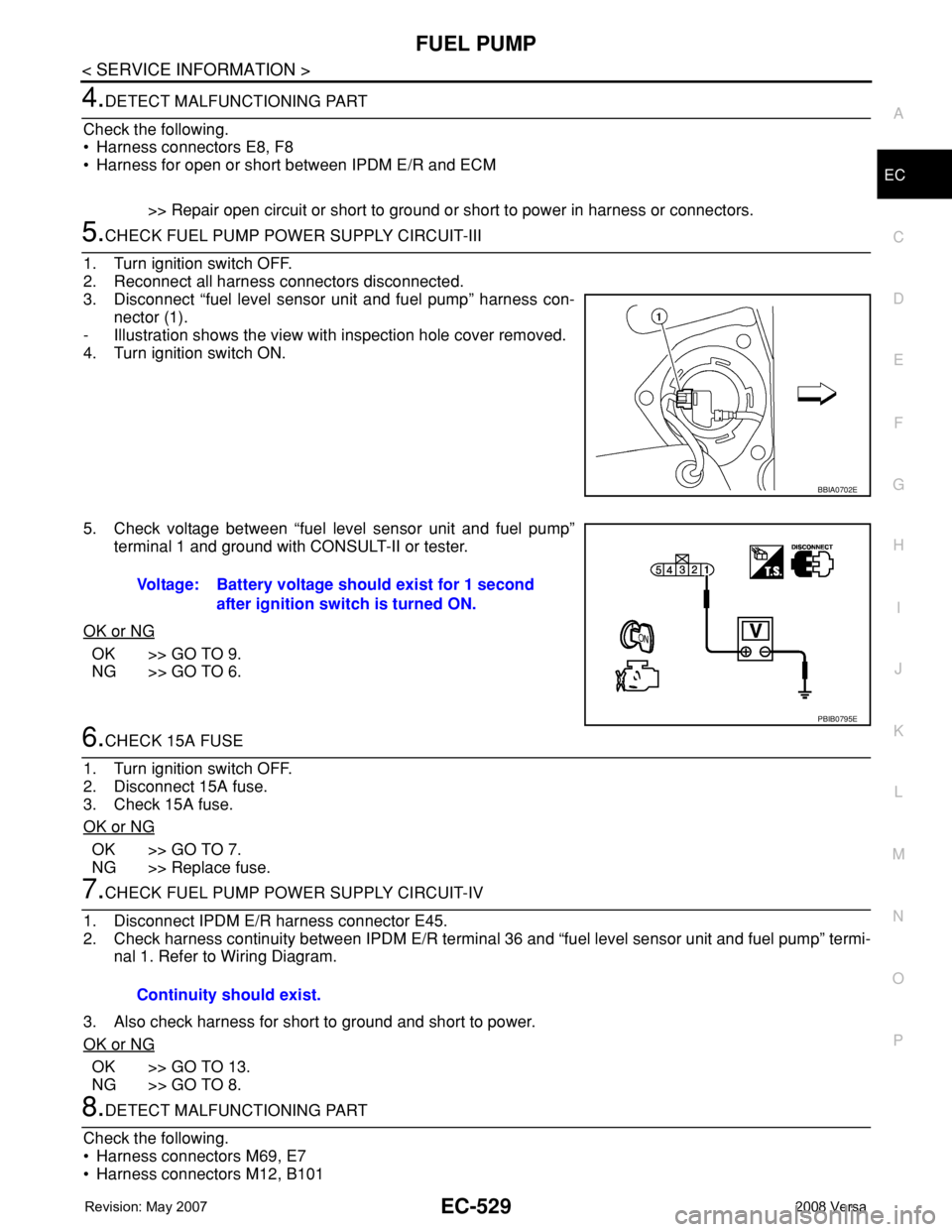
3. Disconnect “fuel level sensor unit and fuel pump” harness con-
nector (1).
- Illustration shows the view with inspection hole cover removed.
4. Turn ignition switch ON.
5. Check voltage between “fuel level sensor unit and fuel pump”
terminal 1 and ground with CONSULT-II or tester.
OK or NG
OK >> GO TO 9.
NG >> GO TO 6.
6.CHECK 15A FUSE
1. Turn ignition switch OFF.
2. Disconnect 15A fuse.
3. Check 15A fuse.
OK or NG
OK >> GO TO 7.
NG >> Replace fuse.
7.CHECK FUEL PUMP POWER SUPPLY CIRCUIT-IV
1. Disconnect IPDM E/R harness connector E45.
2. Check harness continuity between IPDM E/R terminal 36 and “fuel level sensor unit and fuel pump” termi-
nal 1. Refer to Wiring Diagram.
3. Also check harness for short to ground and short to power.
OK or NG
OK >> GO TO 13.
NG >> GO TO 8.
8.DETECT MALFUNCTIONING PART
Check the following.
• Harness connectors M69, E7
• Harness connectors M12, B101
BBIA0702E
Voltage: Battery voltage should exist for 1 second
after ignition switch is turned ON.
PBIB0795E
Continuity should exist.
Page 1613 of 2771
IGNITION SIGNAL
EC-539
< SERVICE INFORMATION >
C
D
E
F
G
H
I
J
K
L
MA
EC
N
P O
1. Turn ignition switch OFF.
2. Disconnect ignition coil harness connector.
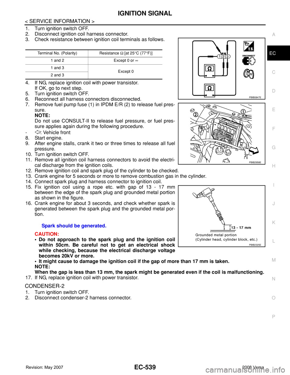
3. Check resistance between ignition coil terminals as follows.
4. If NG, replace ignition coil with power transistor.
If OK, go to next step.
5. Turn ignition switch OFF.
6. Reconnect all harness connectors disconnected.
7. Remove fuel pump fuse (1) in IPDM E/R (2) to release fuel pres-
sure.
NOTE:
Do not use CONSULT-II to release fuel pressure, or fuel pres-
sure applies again during the following procedure.
- : Vehicle front
8. Start engine.
9. After engine stalls, crank it two or three times to release all fuel
pressure.
10. Turn ignition switch OFF.
11. Remove all ignition coil harness connectors to avoid the electri-
cal discharge from the ignition coils.
12. Remove ignition coil and spark plug of the cylinder to be checked.
13. Crank engine for 5 seconds or more to remove combustion gas in the cylinder.
14. Connect spark plug and harness connector to ignition coil.
15. Fix ignition coil using a rope etc. with gap of 13 - 17 mm
between the edge of the spark plug and grounded metal portion
as shown in the figure.
16. Crank engine for about 3 seconds, and check whether spark is
generated between the spark plug and the grounded metal por-
tion.
CAUTION:
• Do not approach to the spark plug and the ignition coil
within 50cm. Be careful not to get an electrical shock
while checking, because the electrical discharge voltage
becomes 20kV or more.
• It might cause to damage the ignition coil if the gap of more than 17 mm is taken.
NOTE:
When the gap is less than 13 mm, the spark might be generated even if the coil is malfunctioning.
17. If NG, replace ignition coil with power transistor.
CONDENSER-2
1. Turn ignition switch OFF.
2. Disconnect condenser-2 harness connector.
Terminal No. (Polarity) Resistance Ω [at 25°C (77°F)]
1 and 2 Except 0 or ∞
1 and 3
Except 0
2 and 3
Spark should be generated.
PBIB0847E
PBIB2958E
PBIB2325E
Page 1712 of 2771

FUEL INJECTOR AND FUEL TUBE
EM-35
< SERVICE INFORMATION >
C
D
E
F
G
H
I
J
K
L
MA
EM
N
P O
8. Remove fuel tube.
• Loosen bolts in reverse order as shown.
9. Remove the fuel tube and fuel injector assembly.
CAUTION:
• When removing, be careful to avoid any interference with fuel injector.
• Use a shop cloth to absorb any fuel leaks from fuel tube.
10. Remove fuel injector from fuel tube with the following procedure:
a. Open and remove clip.
b. Remove fuel injector from fuel tube by pulling straight.
CAUTION:
• Be careful with remaining fuel that may go out from fuel tube.
• Be careful not to damage fuel injector nozzle during removal.
• Never bump or drop fuel injector.
• Never disassemble fuel injector.
INSTALLATION
1. Note the following, and install O-rings to fuel injector.
CAUTION:
• Upper and lower O-rings are different. Be careful not to confuse them.
• Handle O-ring with bare hands. Never wear gloves.
• Lubricate O-ring with new engine oil.
• Never clean O-ring with solvent.
• Make sure that O-ring and its mating part are free of foreign material.
• When installing O-ring, be careful not to scratch it with tool or fingernails. Also be careful not to
twist or stretch O-ring. If O-ring was stretched while it was being attached, never insert it quickly
into fuel tube.
• Insert O-ring straight into fuel tube. Never twist it.
: Engine front
PBIC3154J
Fuel tube side : Black
Nozzle side : Green
Page 1739 of 2771
EM-62
< SERVICE INFORMATION >
CYLINDER HEAD
CYLINDER HEAD
On-Vehicle ServiceINFOID:0000000001702501
CHECKING COMPRESSION PRESSURE
1. Warm up engine thoroughly. Then, stop it.
2. Release fuel pressure. Refer to EC-78, "
Fuel Pressure Check".
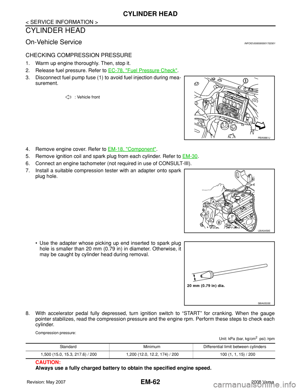
3. Disconnect fuel pump fuse (1) to avoid fuel injection during mea-
surement.
4. Remove engine cover. Refer to EM-18, "
Component".
5. Remove ignition coil and spark plug from each cylinder. Refer to EM-30
.
6. Connect an engine tachometer (not required in use of CONSULT-III).
7. Install a suitable compression tester with an adapter onto spark
plug hole.
• Use the adapter whose picking up end inserted to spark plug
hole is smaller than 20 mm (0.79 in) in diameter. Otherwise, it
may be caught by cylinder head during removal.
8. With accelerator pedal fully depressed, turn ignition switch to “START” for cranking. When the gauge
pointer stabilizes, read the compression pressure and the engine rpm. Perform these steps to check each
cylinder.
Compression pressure:
Unit: kPa (bar, kg/cm2 psi) /rpm
CAUTION:
Always use a fully charged battery to obtain the specified engine speed.
: Vehicle front
PBIA9861J
LBIA0459E
SBIA0533E
Standard Minimum Differential limit between cylinders
1,500 (15.0, 15.3, 217.6) / 200 1,200 (12.0, 12.2, 174) / 200 100 (1, 1, 15) / 200
Page 1867 of 2771
GI-16
< SERVICE INFORMATION >
HOW TO USE THIS MANUAL
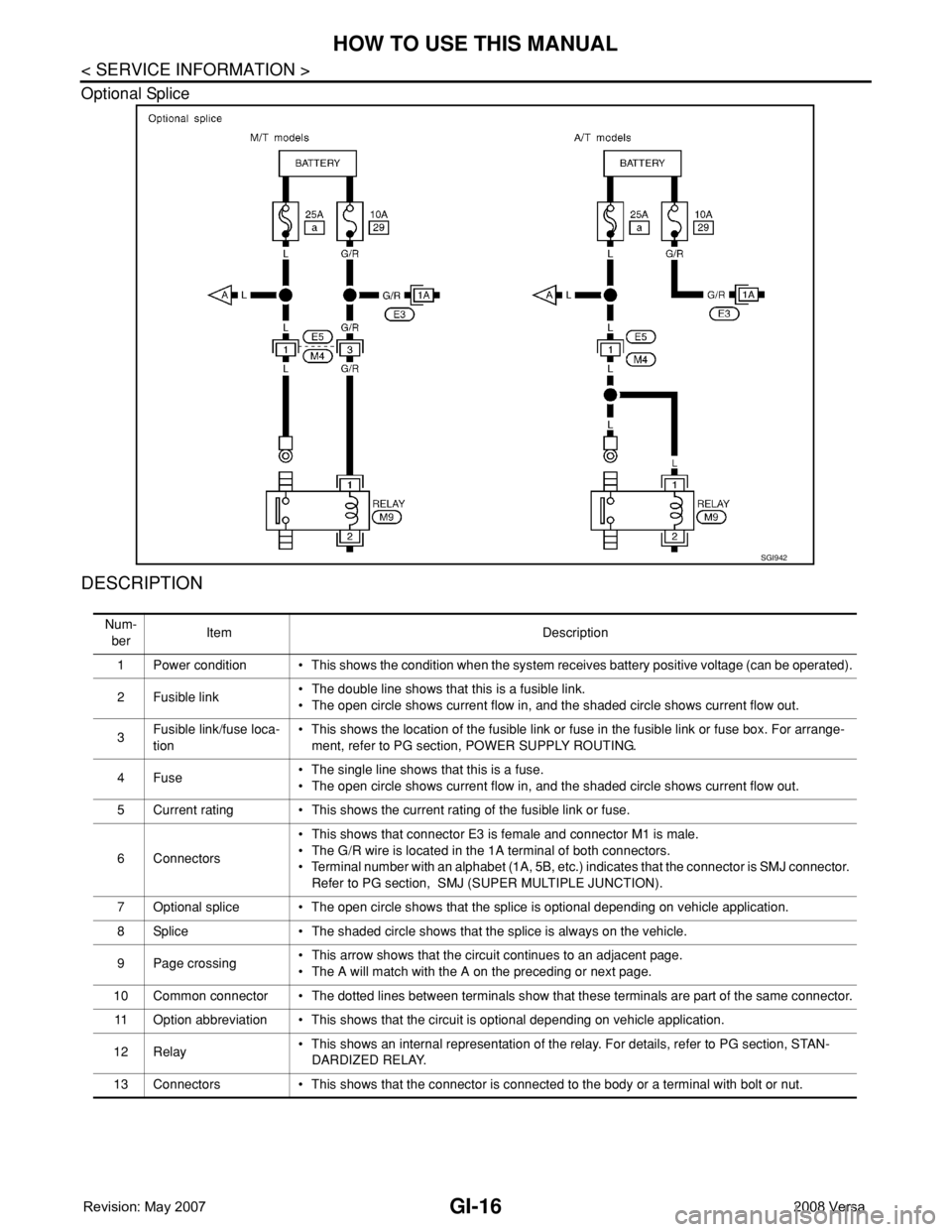
Optional Splice
DESCRIPTION
SGI942
Num-
berItem Description
1 Power condition • This shows the condition when the system receives battery positive voltage (can be operated).
2Fusible link• The double line shows that this is a fusible link.
• The open circle shows current flow in, and the shaded circle shows current flow out.
3Fusible link/fuse loca-
tion• This shows the location of the fusible link or fuse in the fusible link or fuse box. For arrange-
ment, refer to PG section, POWER SUPPLY ROUTING.
4Fuse• The single line shows that this is a fuse.
• The open circle shows current flow in, and the shaded circle shows current flow out.
5 Current rating • This shows the current rating of the fusible link or fuse.
6 Connectors• This shows that connector E3 is female and connector M1 is male.
• The G/R wire is located in the 1A terminal of both connectors.
• Terminal number with an alphabet (1A, 5B, etc.) indicates that the connector is SMJ connector.
Refer to PG section, SMJ (SUPER MULTIPLE JUNCTION).
7 Optional splice • The open circle shows that the splice is optional depending on vehicle application.
8 Splice • The shaded circle shows that the splice is always on the vehicle.
9 Page crossing• This arrow shows that the circuit continues to an adjacent page.
• The A will match with the A on the preceding or next page.
10 Common connector • The dotted lines between terminals show that these terminals are part of the same connector.
11 Option abbreviation • This shows that the circuit is optional depending on vehicle application.
12 Relay• This shows an internal representation of the relay. For details, refer to PG section, STAN-
DARDIZED RELAY.
13 Connectors • This shows that the connector is connected to the body or a terminal with bolt or nut.