Page 3729 of 5121
RAX-4
< ON-VEHICLE REPAIR >
REAR WHEEL HUB AND HOUSING
ON-VEHICLE REPAIR
REAR WHEEL HUB AND HOUSING
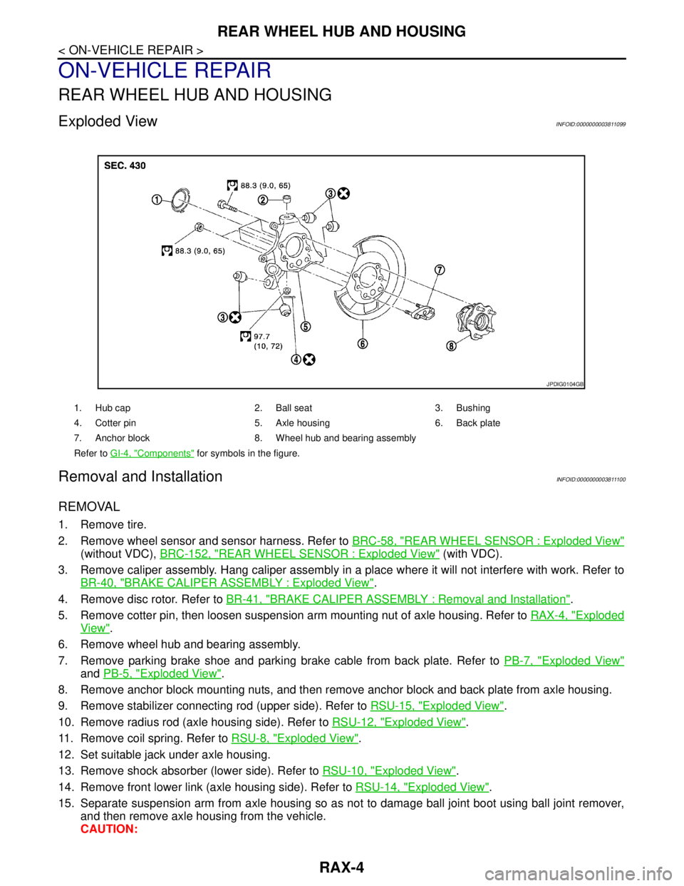
Exploded ViewINFOID:0000000003811099
Removal and InstallationINFOID:0000000003811100
REMOVAL
1. Remove tire.
2. Remove wheel sensor and sensor harness. Refer to BRC-58, "
REAR WHEEL SENSOR : Exploded View"
(without VDC), BRC-152, "REAR WHEEL SENSOR : Exploded View" (with VDC).
3. Remove caliper assembly. Hang caliper assembly in a place where it will not interfere with work. Refer to
BR-40, "
BRAKE CALIPER ASSEMBLY : Exploded View".
4. Remove disc rotor. Refer to BR-41, "
BRAKE CALIPER ASSEMBLY : Removal and Installation".
5. Remove cotter pin, then loosen suspension arm mounting nut of axle housing. Refer to RAX-4, "
Exploded
View".
6. Remove wheel hub and bearing assembly.
7. Remove parking brake shoe and parking brake cable from back plate. Refer to PB-7, "
Exploded View"
and PB-5, "Exploded View".
8. Remove anchor block mounting nuts, and then remove anchor block and back plate from axle housing.
9. Remove stabilizer connecting rod (upper side). Refer to RSU-15, "
Exploded View".
10. Remove radius rod (axle housing side). Refer to RSU-12, "
Exploded View".
11. Remove coil spring. Refer to RSU-8, "
Exploded View".
12. Set suitable jack under axle housing.
13. Remove shock absorber (lower side). Refer to RSU-10, "
Exploded View".
14. Remove front lower link (axle housing side). Refer to RSU-14, "
Exploded View".
15. Separate suspension arm from axle housing so as not to damage ball joint boot using ball joint remover,
and then remove axle housing from the vehicle.
CAUTION:
1. Hub cap 2. Ball seat 3. Bushing
4. Cotter pin 5. Axle housing 6. Back plate
7. Anchor block 8. Wheel hub and bearing assembly
Refer to GI-4, "
Components" for symbols in the figure.
JPDIG0104GB
Page 3730 of 5121
REAR WHEEL HUB AND HOUSING
RAX-5
< ON-VEHICLE REPAIR >
C
E
F
G
H
I
J
K
L
MA
B
RAX
N
O
P
Temporarily tighten nuts to prevent damage to threads and to prevent the ball joint remover from
coming off.
16. Remove hub cap.
INSTALLATION
Note the following, and install in the reverse order of removal.
Perform the final tightening of each of parts under unladen conditions, which were removed when removing
wheel hub and bearing assembly and steering knuckle.
Never reuse cotter pin.
InspectionINFOID:0000000003811101
INSPECTION AFTER REMOVAL
Wheel Hub and Bearing Assembly
Check the wheel hub and bearing assembly for wear, cracks, and damage. Replace if necessary.
Axle Housing
Check the axle housing for wear, cracks, and damage. Replace if necessary.
Ball Joint Inspection
Check for boot breakage, axial looseness, and torque of suspension arm ball joint. Refer to RSU-16, "Inspec-
tion".
INSPECTION AFTER INSTALLATION
1. Check wheel sensor harness for proper connection. Refer to BRC-58, "REAR WHEEL SENSOR :
Exploded View" (without VDC), BRC-152, "REAR WHEEL SENSOR : Exploded View" (with VDC).
2. Adjust parking brake operation (stroke). Refer to PB-2, "
Inspection and Adjustment".
3. Check wheel alignment. Refer to RSU-6, "
Inspection".
4. Adjust neutral position of steering angle sensor (with VDC). Refer to BRC-66, "
ADJUSTMENT OF
STEERING ANGLE SENSOR NEUTRAL POSITION : Special Repair Requirement".
Page 3752 of 5121

BCM (BODY CONTROL MODULE)
RF-21
< ECU DIAGNOSIS >
C
D
E
F
G
H
I
J
L
MA
B
RF
N
O
P
DOOR SW-RLRear LH door closed Off
Rear LH door opened On
DOOR SW-BKNOTE:
The item is indicated, but not monitored. Off
CDL LOCK SWOther than power door lock switch LOCK Off
Power door lock switch LOCK On
CDL UNLOCK SWOther than power door lock switch UNLOCK Off
Power door lock switch UNLOCK On
KEY CYL LK-SWNOTE:
The item is indicated, but not monitored. Off
KEY CYL UN-SWNOTE:
The item is indicated, but not monitored. Off
KEY CYL SW-TRNOTE:
The item is indicated, but not monitored. Off
HAZARD SWHazard switch is OFF Off
Hazard switch is ON On
REAR DEF SW
NOTE:
At model with BOSE au-
dio system this item is in-
dicated, but is not
monitored.Rear window defogger switch is OFF Off
Rear window defogger switch is ON On
TR CANCEL SWNOTE:
The item is indicated, but not monitored. Off
TR/BD OPEN SWTrunk lid opener switch OFF Off
While the trunk lid opener switch is turned ON On
TRNK/HAT MNTRTrunk lid closed Off
Trunk lid opened On
RKE-LOCKLOCK button of the key is not pressed Off
LOCK button of the key is pressed On
RKE-UNLOCKUNLOCK button of the key is not pressed Off
UNLOCK button of the key is pressed On
RKE-TR/BDTRUNK OPEN button of the key is not pressed Off
TRUNK OPEN button of the key is pressed On
RKE-PANICNOTE:
The item is indicated, but not monitored. Off
RKE-P/W OPENNOTE:
The item is indicated, but not monitored. Off
RKE-MODE CHGLOCK/UNLOCK button of the key is not pressed and held simulta-
neouslyOff
LOCK/UNLOCK button of the key is pressed and held simulta-
neouslyOn
OPTICAL SENSORBright outside of the vehicle Close to 5 V
Dark outside of the vehicle Close to 0 V
REQ SW -DRDriver door request switch is not pressed Off
Driver door request switch is pressed On
REQ SW -ASPassenger door request switch is not pressed Off
Passenger door request switch is pressed On Monitor Item Condition Value/Status
Page 3770 of 5121
BCM (BODY CONTROL MODULE)
RF-39
< ECU DIAGNOSIS >
C
D
E
F
G
H
I
J
L
MA
B
RF
N
O
P
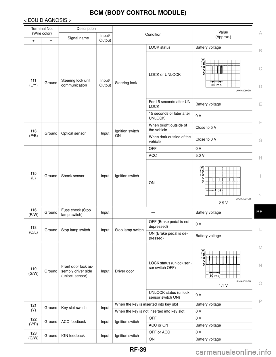
111
(L/Y)GroundSteering lock unit
communicationInput/
OutputSteering lockLOCK status Battery voltage
LOCK or UNLOCK
For 15 seconds after UN-
LOCKBattery voltage
15 seconds or later after
UNLOCK0 V
11 3
(P/B)Ground Optical sensor InputIgnition switch
ONWhen bright outside of
the vehicleClose to 5 V
When dark outside of the
vehicleClose to 0 V
11 5
(L)Ground Shock sensor Input Ignition switchOFF 0 V
ACC 5.0 V
ON
2.5 V
11 6
(R/W)GroundFuse check (Stop
lamp switch)Input — Battery voltage
11 8
(O/L)Ground Stop lamp switch Input Stop lamp switchOFF (Brake pedal is not
depressed)0 V
ON (Brake pedal is de-
pressed)Battery voltage
11 9
(G/W)GroundFront door lock as-
sembly driver side
(unlock sensor)Input Driver doorLOCK status (unlock sen-
sor switch OFF)
1.1 V
UNLOCK status (unlock
sensor switch ON)0 V
121
(Y)Ground Key slot switch InputWhen the key is inserted into key slot Battery voltage
When the key is not inserted into key slot 0 V
122
(V/R)Ground ACC feedback Input Ignition switchOFF 0 V
ACC or ON Battery voltage
123
(G/W)Ground IGN feedback Input Ignition switchOFF or ACC 0 V
ON Battery voltage Te r m i n a l N o .
(Wire color)Description
ConditionVa l u e
(Approx.)
Signal nameInput/
Output +–
JMKIA0066GB
JPMIA1034GB
JPMIA0012GB
Page 3841 of 5121

REAR LOWER LINK & COIL SPRING
RSU-9
< ON-VEHICLE REPAIR >
C
D
F
G
H
I
J
K
L
MA
B
RSU
N
O
P
Install coil spring by aligning lower end of the coil spring to step (A)
between rubber seat (1) and rear lower link (2).
CAUTION:
Set coil spring so that its paint marks are aligned with the
positions of 3.0 turns (2 places) and 4.0 turns (1 place) or 4.0
turns (2 places) and 5.0 turns (1 place) from the bottom end of
the coil spring.
Perform the final tightening of rear suspension member and axle
installation position (rubber bushing) under unladen condition with
tires on level ground.
InspectionINFOID:0000000003811144
INSPECTION AFTER REMOVAL
Check lower link, bushing and coil spring for deformation, crack, and damage. Replace if necessary.
INSPECTION AFTER INSTALLATION
1. Check wheel alignment. Refer to RSU-6, "Inspection".
2. Adjust neutral position of steering angle sensor (with VDC). Refer to BRC-66, "
ADJUSTMENT OF
STEERING ANGLE SENSOR NEUTRAL POSITION : Special Repair Requirement".
JPEIB0122ZZ
Page 3842 of 5121
RSU-10
< ON-VEHICLE REPAIR >
REAR SHOCK ABSORBER
REAR SHOCK ABSORBER
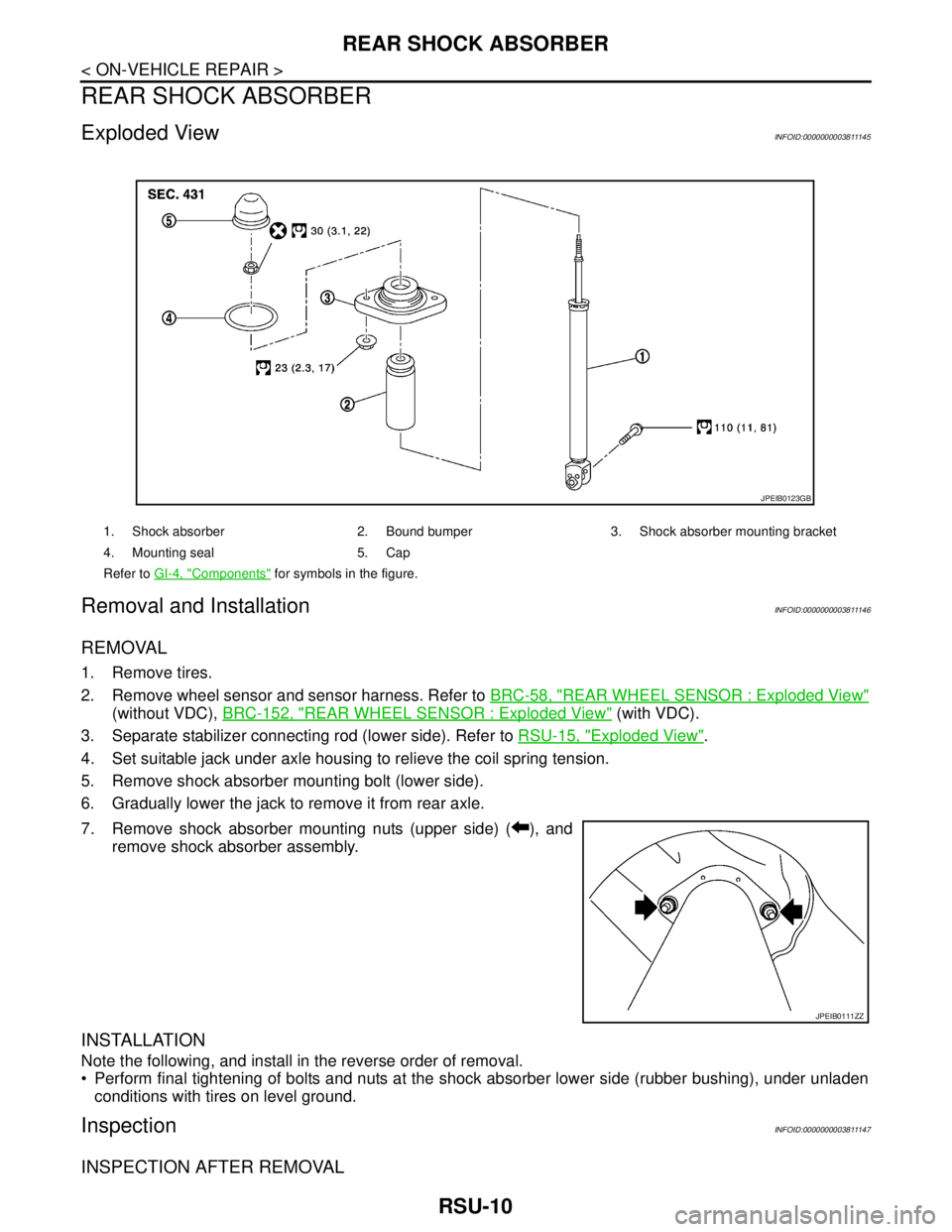
Exploded ViewINFOID:0000000003811145
Removal and InstallationINFOID:0000000003811146
REMOVAL
1. Remove tires.
2. Remove wheel sensor and sensor harness. Refer to BRC-58, "
REAR WHEEL SENSOR : Exploded View"
(without VDC), BRC-152, "REAR WHEEL SENSOR : Exploded View" (with VDC).
3. Separate stabilizer connecting rod (lower side). Refer to RSU-15, "
Exploded View".
4. Set suitable jack under axle housing to relieve the coil spring tension.
5. Remove shock absorber mounting bolt (lower side).
6. Gradually lower the jack to remove it from rear axle.
7. Remove shock absorber mounting nuts (upper side) ( ), and
remove shock absorber assembly.
INSTALLATION
Note the following, and install in the reverse order of removal.
Perform final tightening of bolts and nuts at the shock absorber lower side (rubber bushing), under unladen
conditions with tires on level ground.
InspectionINFOID:0000000003811147
INSPECTION AFTER REMOVAL
1. Shock absorber 2. Bound bumper 3. Shock absorber mounting bracket
4. Mounting seal 5. Cap
Refer to GI-4, "
Components" for symbols in the figure.
JPEIB0123GB
JPEIB0111ZZ
Page 3843 of 5121
REAR SHOCK ABSORBER
RSU-11
< ON-VEHICLE REPAIR >
C
D
F
G
H
I
J
K
L
MA
B
RSU
N
O
P
Check the following items, and replace the if necessary.
Shock absorber for deformation, cracks, damage.
Welded and sealed areas for oil leakage.
Piston rod for damage, uneven wear or distortion.
Seal of shock absorber mounting bracket for cracks, damage and come off.
INSPECTION AFTER INSTALLATION
Check wheel sensor harness for proper connection. Refer to BRC-58, "REAR WHEEL SENSOR : Exploded
View" (without VDC), BRC-152, "REAR WHEEL SENSOR : Exploded View" (with VDC).
Page 3844 of 5121
RSU-12
< ON-VEHICLE REPAIR >
RADIUS ROD
RADIUS ROD
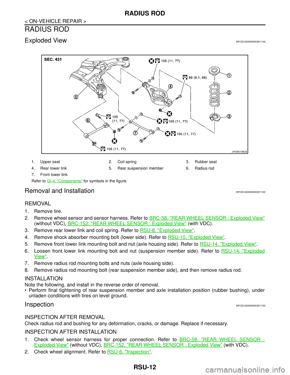
Exploded ViewINFOID:0000000003811148
Removal and InstallationINFOID:0000000003811149
REMOVAL
1. Remove tire.
2. Remove wheel sensor and sensor harness. Refer to BRC-58, "
REAR WHEEL SENSOR : Exploded View"
(without VDC), BRC-152, "REAR WHEEL SENSOR : Exploded View" (with VDC).
3. Remove rear lower link and coil spring. Refer to RSU-8, "
Exploded View".
4. Remove shock absorber mounting bolt (lower side). Refer to RSU-10, "
Exploded View".
5. Remove front lower link mounting bolt and nut (axle housing side). Refer to RSU-14, "
Exploded View".
6. Loosen front lower link mounting bolt and nut (suspension member side). Refer to RSU-14, "
Exploded
View".
7. Remove radius rod mounting bolts and nuts (axle housing side).
8. Remove radius rod mounting bolt (rear suspension member side), and then remove radius rod.
INSTALLATION
Note the following, and install in the reverse order of removal.
Perform final tightening of rear suspension member and axle installation position (rubber bushing), under
unladen conditions with tires on level ground.
InspectionINFOID:0000000003811150
INSPECTION AFTER REMOVAL
Check radius rod and bushing for any deformation, cracks, or damage. Replace if necessary.
INSPECTION AFTER INSTALLATION
1. Check wheel sensor harness for proper connection. Refer to BRC-58, "REAR WHEEL SENSOR :
Exploded View" (without VDC), BRC-152, "REAR WHEEL SENSOR : Exploded View" (with VDC).
2. Check wheel alignment. Refer to RSU-6, "
Inspection".
1. Upper seat 2. Coil spring 3. Rubber seat
4. Rear lower link 5. Rear suspension member 6. Radius rod
7. Front lower link
Refer to GI-4, "
Components" for symbols in the figure.
JPEIB0108GB