2008 NISSAN TEANA sensor
[x] Cancel search: sensorPage 4235 of 5121
SIDE AIR BAG (SATELLITE) SENSOR
SR-21
< ON-VEHICLE REPAIR >
C
D
E
F
G
I
J
K
L
MA
B
SR
N
O
P
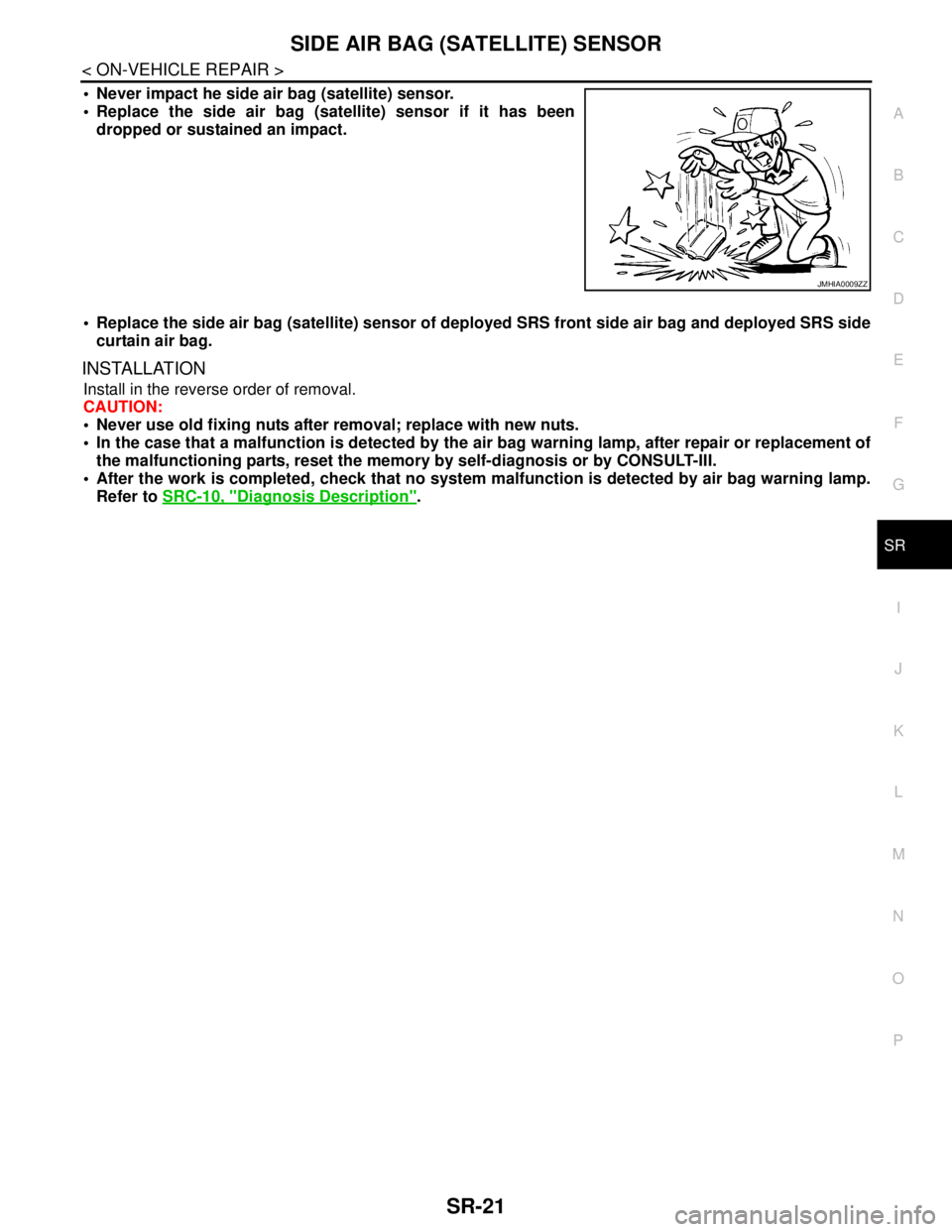
Never impact he side air bag (satellite) sensor.
Replace the side air bag (satellite) sensor if it has been
dropped or sustained an impact.
Replace the side air bag (satellite) sensor of deployed SRS front side air bag and deployed SRS side
curtain air bag.
INSTALLATION
Install in the reverse order of removal.
CAUTION:
Never use old fixing nuts after removal; replace with new nuts.
In the case that a malfunction is detected by the air bag warning lamp, after repair or replacement of
the malfunctioning parts, reset the memory by self-diagnosis or by CONSULT-III.
After the work is completed, check that no system malfunction is detected by air bag warning lamp.
Refer to SRC-10, "
Diagnosis Description".
JMHIA0009ZZ
Page 4236 of 5121
SR-22
< ON-VEHICLE REPAIR >
DIAGNOSIS SENSOR UNIT
DIAGNOSIS SENSOR UNIT
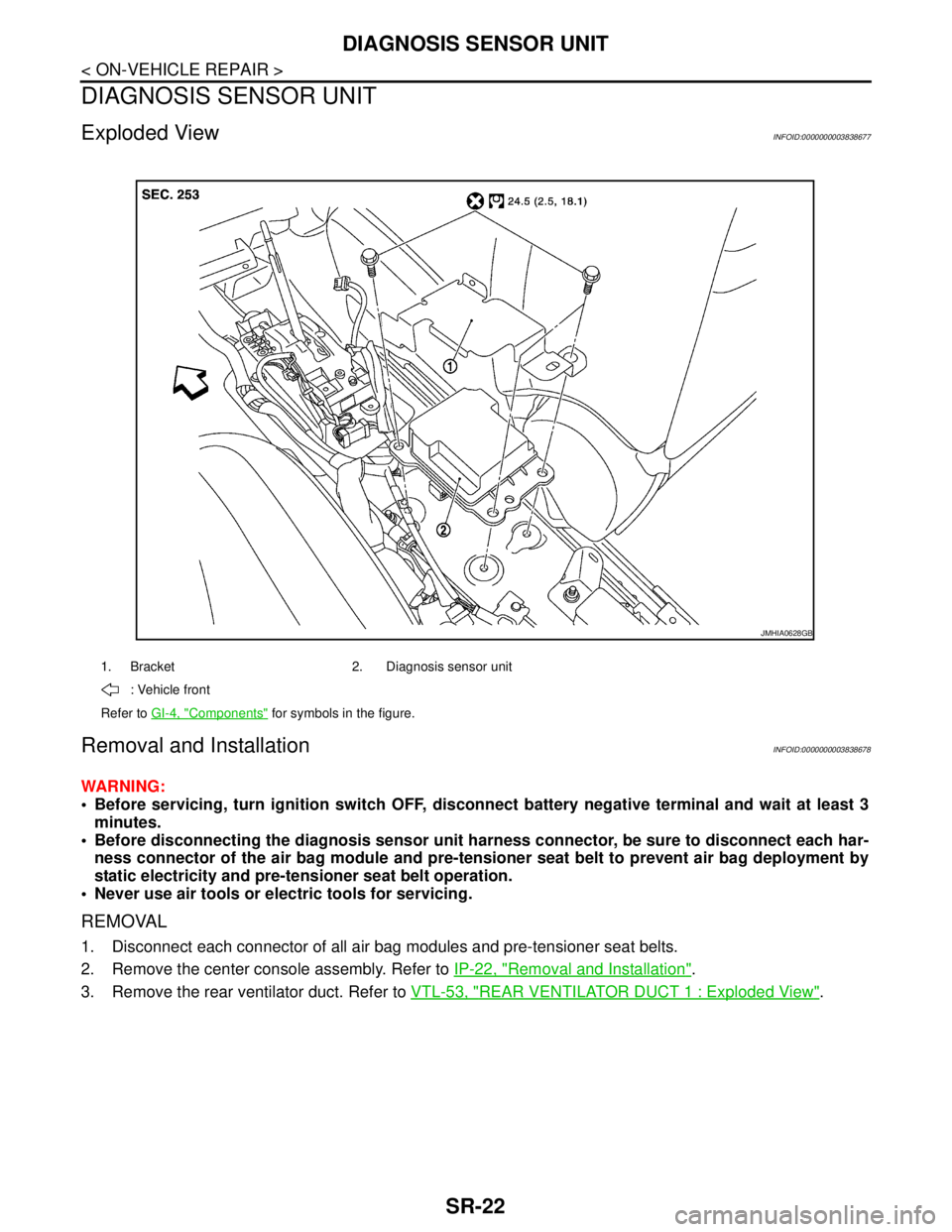
Exploded ViewINFOID:0000000003838677
Removal and InstallationINFOID:0000000003838678
WARNING:
Before servicing, turn ignition switch OFF, disconnect battery negative terminal and wait at least 3
minutes.
Before disconnecting the diagnosis sensor unit harness connector, be sure to disconnect each har-
ness connector of the air bag module and pre-tensioner seat belt to prevent air bag deployment by
static electricity and pre-tensioner seat belt operation.
Never use air tools or electric tools for servicing.
REMOVAL
1. Disconnect each connector of all air bag modules and pre-tensioner seat belts.
2. Remove the center console assembly. Refer to IP-22, "
Removal and Installation".
3. Remove the rear ventilator duct. Refer to VTL-53, "
REAR VENTILATOR DUCT 1 : Exploded View".
1. Bracket 2. Diagnosis sensor unit
: Vehicle front
Refer to GI-4, "
Components" for symbols in the figure.
JMHIA0628GB
Page 4237 of 5121
DIAGNOSIS SENSOR UNIT
SR-23
< ON-VEHICLE REPAIR >
C
D
E
F
G
I
J
K
L
MA
B
SR
N
O
P
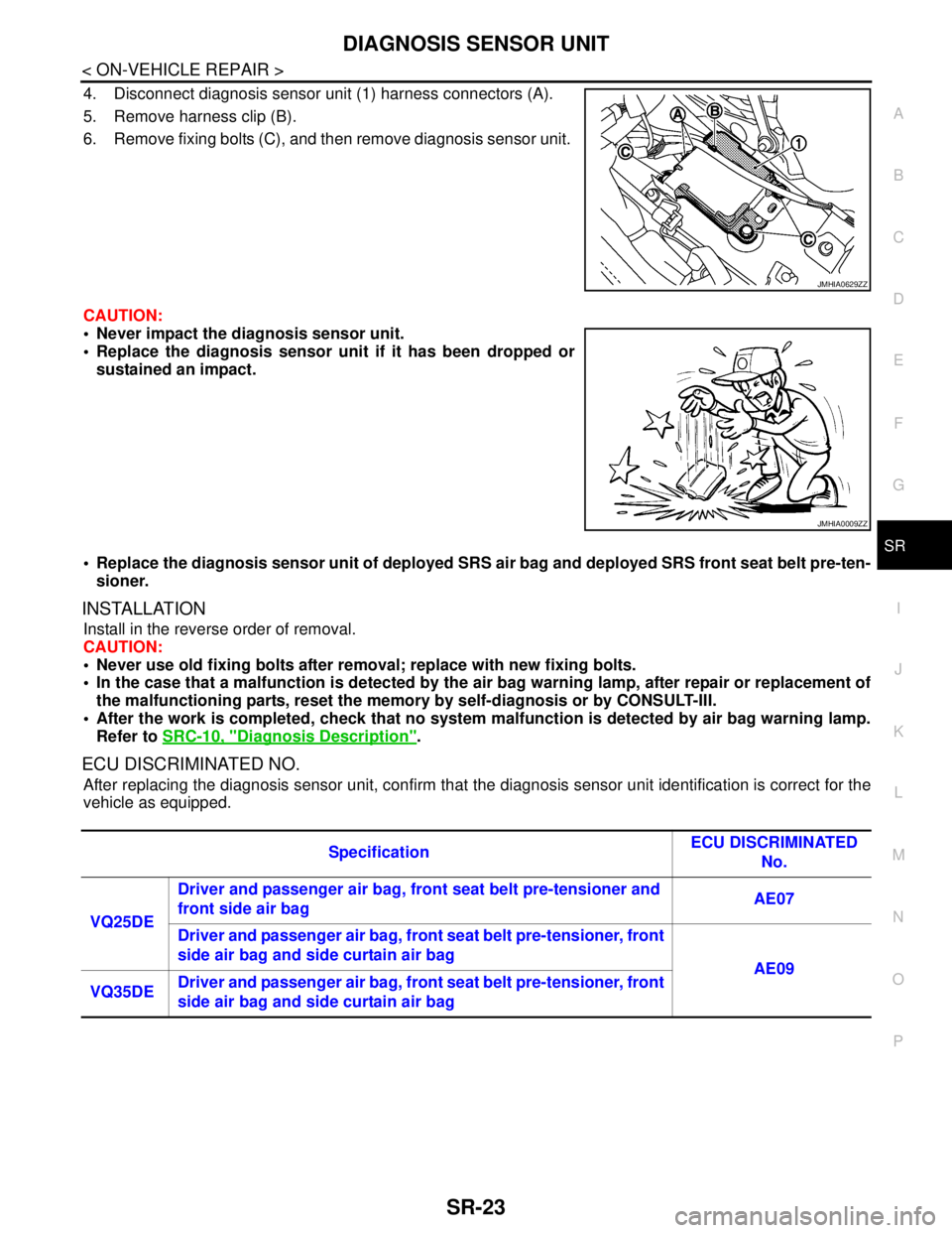
4. Disconnect diagnosis sensor unit (1) harness connectors (A).
5. Remove harness clip (B).
6. Remove fixing bolts (C), and then remove diagnosis sensor unit.
CAUTION:
Never impact the diagnosis sensor unit.
Replace the diagnosis sensor unit if it has been dropped or
sustained an impact.
Replace the diagnosis sensor unit of deployed SRS air bag and deployed SRS front seat belt pre-ten-
sioner.
INSTALLATION
Install in the reverse order of removal.
CAUTION:
Never use old fixing bolts after removal; replace with new fixing bolts.
In the case that a malfunction is detected by the air bag warning lamp, after repair or replacement of
the malfunctioning parts, reset the memory by self-diagnosis or by CONSULT-III.
After the work is completed, check that no system malfunction is detected by air bag warning lamp.
Refer to SRC-10, "
Diagnosis Description".
ECU DISCRIMINATED NO.
After replacing the diagnosis sensor unit, confirm that the diagnosis sensor unit identification is correct for the
vehicle as equipped.
JMHIA0629ZZ
JMHIA0009ZZ
SpecificationECU DISCRIMINATED
No.
VQ25DE Driver and passenger air bag, front seat belt pre-tensioner and
front side air bag AE07
Driver and passenger air bag, front seat belt pre-tensioner, front
side air bag and side curtain air bag
AE09
VQ35DEDriver and passenger air bag, front seat belt pre-tensioner, front
side air bag and side curtain air bag
Page 4244 of 5121
SRC-1
RESTRAINTS
C
D
E
F
G
I
J
K
L
M
SECTION SRC
A
B
SRC
N
O
P
CONTENTS
SRS AIRBAG CONTROL SYSTEM
BASIC INSPECTION ....................................5
DIAGNOSIS AND REPAIR WORK FLOW .........5
Work Flow .................................................................5
FUNCTION DIAGNOSIS ...............................7
SRS AIR BAG SYSTEM ......................................7
System Diagram ........................................................7
System Description ...................................................7
Component Parts Location ........................................8
Component Description .............................................8
DIAGNOSIS SYSTEM (AIRBAG) ......................10
Diagnosis Description .............................................10
Air Bag Warning Lamp Diagnosis ...........................10
CONSULT-III Function ............................................15
COMPONENT DIAGNOSIS .........................16
B1001, B1002, B1003, B1004, B1005 DIAG-
NOSIS SENSOR UNIT .......................................
16
Description ..............................................................16
DTC Logic ...............................................................16
Diagnosis Procedure ...............................................16
B1006, B1007, B1008, B1009, B1010 DIAG-
NOSIS SENSOR UNIT .......................................
18
Description ..............................................................18
DTC Logic ...............................................................18
Diagnosis Procedure ...............................................18
B1011, B1012, B1013, B1014, B1015 DIAG-
NOSIS SENSOR UNIT .......................................
20
Description ..............................................................20
DTC Logic ...............................................................20
Diagnosis Procedure ...............................................20
B1026, B1027, B1028, B1029, B1030, B1031
DIAGNOSIS SENSOR UNIT ..............................
22
Description ..............................................................22
DTC Logic ...............................................................22
Diagnosis Procedure ...............................................22
B1033, B1034 CRASH ZONE SEN ..................24
Description ...............................................................24
DTC Logic ................................................................24
Diagnosis Procedure ...............................................24
B1035, B1036 CRASH ZONE SEN ..................26
Description ...............................................................26
DTC Logic ................................................................26
Diagnosis Procedure ...............................................26
B1037, B1039, B1041 CRASH ZONE SENS1 ...28
Description ...............................................................28
DTC Logic ................................................................28
Diagnosis Procedure ...............................................28
B1042, B1043, B1044, B1045, B1046, B1047
DIAGNOSIS SENSOR UNIT .............................
30
Description ...............................................................30
DTC Logic ................................................................30
Diagnosis Procedure ...............................................30
B1049 DRIVER AIRBAG MODULE ..................32
Description ...............................................................32
DTC Logic ................................................................32
Diagnosis Procedure ...............................................32
B1050 DRIVER AIRBAG MODULE ..................34
Description ...............................................................34
DTC Logic ................................................................34
Diagnosis Procedure ...............................................34
B1051 DRIVER AIRBAG MODULE ..................36
Description ...............................................................36
DTC Logic ................................................................36
Diagnosis Procedure ...............................................36
B1052 DRIVER AIRBAG MODULE ..................38
Description ...............................................................38
DTC Logic ................................................................38
Diagnosis Procedure ...............................................38
Page 4245 of 5121

SRC-2
B1058, B1059, B1060, B1061, B1062, B1063
DIAGNOSIS SENSOR UNIT ..............................
40
Description ..............................................................40
DTC Logic ...............................................................40
Diagnosis Procedure ..............................................40
B1065 ASSIST A/B MODULE ...........................42
Description ..............................................................42
DTC Logic ...............................................................42
Diagnosis Procedure ..............................................42
B1066 ASSIST A/B MODULE ...........................44
Description ..............................................................44
DTC Logic ...............................................................44
Diagnosis Procedure ..............................................44
B1067 ASSIST A/B MODULE ...........................46
Description ..............................................................46
DTC Logic ...............................................................46
Diagnosis Procedure ..............................................46
B1068 ASSIST A/B MODULE ...........................48
Description ..............................................................48
DTC Logic ...............................................................48
Diagnosis Procedure ..............................................48
B1074, B1075, B1076, B1077, B1078, B1079
DIAGNOSIS SENSOR UNIT ..............................
50
Description ..............................................................50
DTC Logic ...............................................................50
Diagnosis Procedure ..............................................50
B1081 PRE-TEN FRONT RH ............................52
Description ..............................................................52
DTC Logic ...............................................................52
Diagnosis Procedure ..............................................52
B1082 PRE-TEN FRONT RH ............................54
Description ..............................................................54
DTC Logic ...............................................................54
Diagnosis Procedure ..............................................54
B1083 PRE-TEN FRONT RH ............................56
Description ..............................................................56
DTC Logic ...............................................................56
Diagnosis Procedure ..............................................56
B1084 PRE-TEN FRONT RH ............................58
Description ..............................................................58
DTC Logic ...............................................................58
Diagnosis Procedure ..............................................58
B1086 PRE-TEN FRONT LH .............................60
Description ..............................................................60
DTC Logic ...............................................................60
Diagnosis Procedure ..............................................60
B1087 PRE-TEN FRONT LH .............................62
Description ..............................................................62
DTC Logic ...............................................................62
Diagnosis Procedure ..............................................62
B1088 PRE-TEN FRONT LH .............................64
Description ..............................................................64
DTC Logic ...............................................................64
Diagnosis Procedure ...............................................64
B1089 PRE-TEN FRONT LH .............................66
Description ..............................................................66
DTC Logic ...............................................................66
Diagnosis Procedure ...............................................66
B1090, B1091, B1092, B1093, B1094, B1095
CONTROL UNIT ................................................
68
Description ..............................................................68
DTC Logic ...............................................................68
Diagnosis Procedure ...............................................68
B1106, B1107, B1108, B1109, B1110, B1111
DIAGNOSIS SENSOR UNIT .............................
70
Description ..............................................................70
DTC Logic ...............................................................70
Diagnosis Procedure ...............................................70
B1113, B1114 SATELLITE SENS RH ..............72
Description ..............................................................72
DTC Logic ...............................................................72
Diagnosis Procedure ...............................................72
B1115, B1116 SATELLITE SENS RH ..............74
Description ..............................................................74
DTC Logic ...............................................................74
Diagnosis Procedure ...............................................74
B1118, B1119 SATELLITE SENS LH ...............76
Description ..............................................................76
DTC Logic ...............................................................76
Diagnosis Procedure ...............................................76
B1120, B1121 SATELLITE SENS LH ...............78
Description ..............................................................78
DTC Logic ...............................................................78
Diagnosis Procedure ...............................................78
B1122, B1123, B1124, B1125, B1126, B1127
DIAGNOSIS SENSOR UNIT .............................
80
Description ..............................................................80
DTC Logic ...............................................................80
Diagnosis Procedure ...............................................80
B1129 SIDE MODULE RH ................................82
Description ..............................................................82
DTC Logic ...............................................................82
Diagnosis Procedure ...............................................82
B1130 SIDE MODULE RH ................................84
Description ..............................................................84
DTC Logic ...............................................................84
Diagnosis Procedure ...............................................84
B1131 SIDE MODULE RH ................................86
Description ..............................................................86
DTC Logic ...............................................................86
Page 4246 of 5121
SRC-3
C
D
E
F
G
I
J
K
L
MA
B
SRC
N
O
P Diagnosis Procedure ...............................................
86
B1132 SIDE MODULE RH .................................88
Description ..............................................................88
DTC Logic ...............................................................88
Diagnosis Procedure ...............................................88
B1134 SIDE MODULE LH ..................................90
Description ..............................................................90
DTC Logic ...............................................................90
Diagnosis Procedure ...............................................90
B1135 SIDE MODULE LH ..................................92
Description ..............................................................92
DTC Logic ...............................................................92
Diagnosis Procedure ...............................................92
B1136 SIDE MODULE LH ..................................94
Description ..............................................................94
DTC Logic ...............................................................94
Diagnosis Procedure ...............................................94
B1137 SIDE MODULE LH ..................................96
Description ..............................................................96
DTC Logic ...............................................................96
Diagnosis Procedure ...............................................96
B1138, B1139, B1140, B1141, B1142, B1143
DIAGNOSIS SENSOR UNIT ..............................
98
Description ..............................................................98
DTC Logic ...............................................................98
Diagnosis Procedure ...............................................98
B1144 ACU .......................................................100
Description ............................................................100
DTC Logic .............................................................100
Diagnosis Procedure .............................................100
B1145 CURTAIN MODULE RH .......................102
Description ............................................................102
DTC Logic .............................................................102
Diagnosis Procedure .............................................102
B1146 CURTAIN MODULE RH .......................104
Description ............................................................104
DTC Logic .............................................................104
Diagnosis Procedure .............................................104
B1147 CURTAIN MODULE RH .......................106
Description ............................................................106
DTC Logic .............................................................106
Diagnosis Procedure .............................................106
B1148 CURTAIN MODULE RH .......................108
Description ............................................................108
DTC Logic .............................................................108
Diagnosis Procedure .............................................108
B1150 CURTAIN MODULE LH ........................110
Description ............................................................110
DTC Logic .............................................................110
Diagnosis Procedure .............................................110
B1151 CURTAIN MODULE LH .......................112
Description .............................................................112
DTC Logic ..............................................................112
Diagnosis Procedure .............................................112
B1152 CURTAIN MODULE LH .......................114
Description .............................................................114
DTC Logic ..............................................................114
Diagnosis Procedure .............................................114
B1153 CURTAIN MODULE LH .......................116
Description .............................................................116
DTC Logic ..............................................................116
Diagnosis Procedure .............................................116
B1154, B1157, B1170, B1171, B1172, B1173,
B1174, B1175 CONTROL UNIT .....................
118
Description .............................................................118
DTC Logic ..............................................................118
Diagnosis Procedure .............................................118
B1202, B1203, B1204, B1205, B1206, B1207
DIAGNOSIS SENSOR UNIT ...........................
120
Description .............................................................120
DTC Logic ..............................................................120
Diagnosis Procedure .............................................120
B1209 FRONTAL COLLISION DETECTION ..122
Description .............................................................122
DTC Logic ..............................................................122
Diagnosis Procedure .............................................122
B1210 SIDE COLLISION DETECTION ..........124
Description .............................................................124
DTC Logic ..............................................................124
Diagnosis Procedure .............................................124
B1212, B1213, B1214 RH1 SAT-SENS ..........126
Description .............................................................126
DTC Logic ..............................................................126
Diagnosis Procedure .............................................126
B1215, B1216, B1217 LH1 SAT-SENS ..........128
Description .............................................................128
DTC Logic ..............................................................128
Diagnosis Procedure .............................................128
B1218, B1219, B1220, B1221, B1222, B1223
CONTROL UNIT ..............................................
130
Description .............................................................130
DTC Logic ..............................................................130
Diagnosis Procedure .............................................130
ECU DIAGNOSIS .......................................132
DIAGNOSIS SENSOR UNIT ...........................132
DTC Index .............................................................132
Wiring Diagram - SRS AIR BAG CONTROL SYS-
TEM - .....................................................................
139
SYMPTOM DIAGNOSIS ............................145
Page 4251 of 5121
SRC-8
< FUNCTION DIAGNOSIS >
SRS AIR BAG SYSTEM
3. Detects and records the deployment of air bag and seat belt pre-tensioner, and turns on air bag warning
lamp.
4. Indicates malfunctioning portion with blinking times of air bag warning lamp in diagnosis mode.
5. Indicates the malfunctioning record by CONSULT-III.
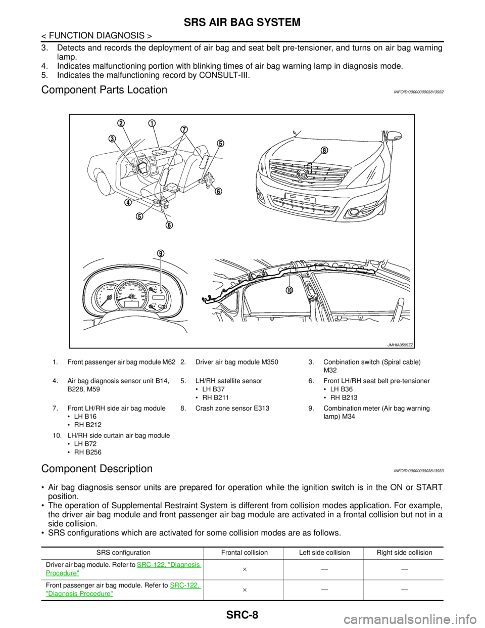
Component Parts LocationINFOID:0000000003813932
Component DescriptionINFOID:0000000003813933
Air bag diagnosis sensor units are prepared for operation while the ignition switch is in the ON or START
position.
The operation of Supplemental Restraint System is different from collision modes application. For example,
the driver air bag module and front passenger air bag module are activated in a frontal collision but not in a
side collision.
SRS configurations which are activated for some collision modes are as follows.
1. Front passenger air bag module M62 2. Driver air bag module M350 3. Conbination switch (Spiral cable)
M32
4. Air bag diagnosis sensor unit B14,
B228, M595. LH/RH satellite sensor
LH B37
RH B2116. Front LH/RH seat belt pre-tensioner
LH B36
RH B213
7. Front LH/RH side air bag module
LH B16
RH B2128. Crash zone sensor E313 9. Combination meter (Air bag warning
lamp) M34
10. LH/RH side curtain air bag module
LH B72
RH B256
JMHIA0599ZZ
SRS configuration Frontal collision Left side collision Right side collision
Driver air bag module. Refer to SRC-122, "
Diagnosis
Procedure"×——
Front passenger air bag module. Refer to SRC-122,
"Diagnosis Procedure"×——
Page 4255 of 5121
SRC-12
< FUNCTION DIAGNOSIS >
DIAGNOSIS SYSTEM (AIRBAG)
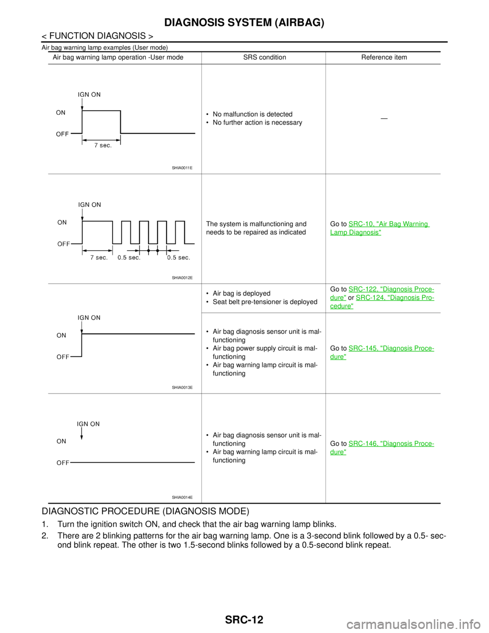
Air bag warning lamp examples (User mode)
DIAGNOSTIC PROCEDURE (DIAGNOSIS MODE)
1. Turn the ignition switch ON, and check that the air bag warning lamp blinks.
2. There are 2 blinking patterns for the air bag warning lamp. One is a 3-second blink followed by a 0.5- sec-
ond blink repeat. The other is two 1.5-second blinks followed by a 0.5-second blink repeat.
Air bag warning lamp operation -User mode SRS condition Reference item
No malfunction is detected
No further action is necessary—
The system is malfunctioning and
needs to be repaired as indicatedGo to SRC-10, "
Air Bag Warning
Lamp Diagnosis"
Air bag is deployed
Seat belt pre-tensioner is deployedGo to SRC-122, "Diagnosis Proce-
dure" or SRC-124, "Diagnosis Pro-
cedure"
Air bag diagnosis sensor unit is mal-
functioning
Air bag power supply circuit is mal-
functioning
Air bag warning lamp circuit is mal-
functioningGo to SRC-145, "
Diagnosis Proce-
dure"
Air bag diagnosis sensor unit is mal-
functioning
Air bag warning lamp circuit is mal-
functioningGo to SRC-146, "
Diagnosis Proce-
dure"
SHIA0011E
SHIA0012E
SHIA0013E
SHIA0014E