Page 3294 of 5121
MWI-40
< COMPONENT DIAGNOSIS >
B2267 ENGINE SPEED
B2267 ENGINE SPEED
DescriptionINFOID:0000000003792561
The engine speed signal is transmitted from ECM to the combination meter via CAN communication.
DTC LogicINFOID:0000000003792562
DTC DETECTION LOGIC
Diagnosis ProcedureINFOID:0000000003792563
1.PERFORM SELF-DIAGNOSIS OF ECM
Perform “Self Diagnostic Result” of ECM, and repair or replace malfunctioning parts.
>> Refer to EC-113, "
CONSULT-III Function".
DTCDisplay contents of
CONSULT-IIIDiagnostic item is detected when ... Probable malfunction location
B2267 ENGINE SPEEDECM continuously transmits abnormal engine
speed signals for 2 seconds or more Crankshaft position sensor (POS)
ECM
Page 3295 of 5121
MWI
B2268 WATER TEMP
MWI-41
< COMPONENT DIAGNOSIS >
C
D
E
F
G
H
I
J
K
L
MB A
O
P
B2268 WATER TEMP
DescriptionINFOID:0000000003792564
The engine coolant temperature signal is transmitted from ECM to the combination meter via CAN communi-
cation.
DTC LogicINFOID:0000000003792565
DTC DETECTION LOGIC
Diagnosis ProcedureINFOID:0000000003792566
1.PERFORM SELF-DIAGNOSIS OF ECM
Perform “Self Diagnosis Result” of ECM, and repair or replace malfunctioning parts.
>> Refer to EC-113, "
CONSULT-III Function".
DTCDisplay contents of
CONSULT-IIIDiagnostic item is detected when ... Probable malfunction location
B2268 WATER TEMPECM continuously transmits abnormal engine
coolant temperature signals for 60 seconds or
more Engine coolant temperature sensor
ECM
Page 3299 of 5121

MWI
FUEL LEVEL SENSOR SIGNAL CIRCUIT
MWI-45
< COMPONENT DIAGNOSIS >
C
D
E
F
G
H
I
J
K
L
MB A
O
P
FUEL LEVEL SENSOR SIGNAL CIRCUIT
DescriptionINFOID:0000000003792570
The fuel level sensor unit and fuel pump detect the fuel level in the fuel tank and transmit the fuel gauge signal
to the combination meter.
Component Function CheckINFOID:0000000003792571
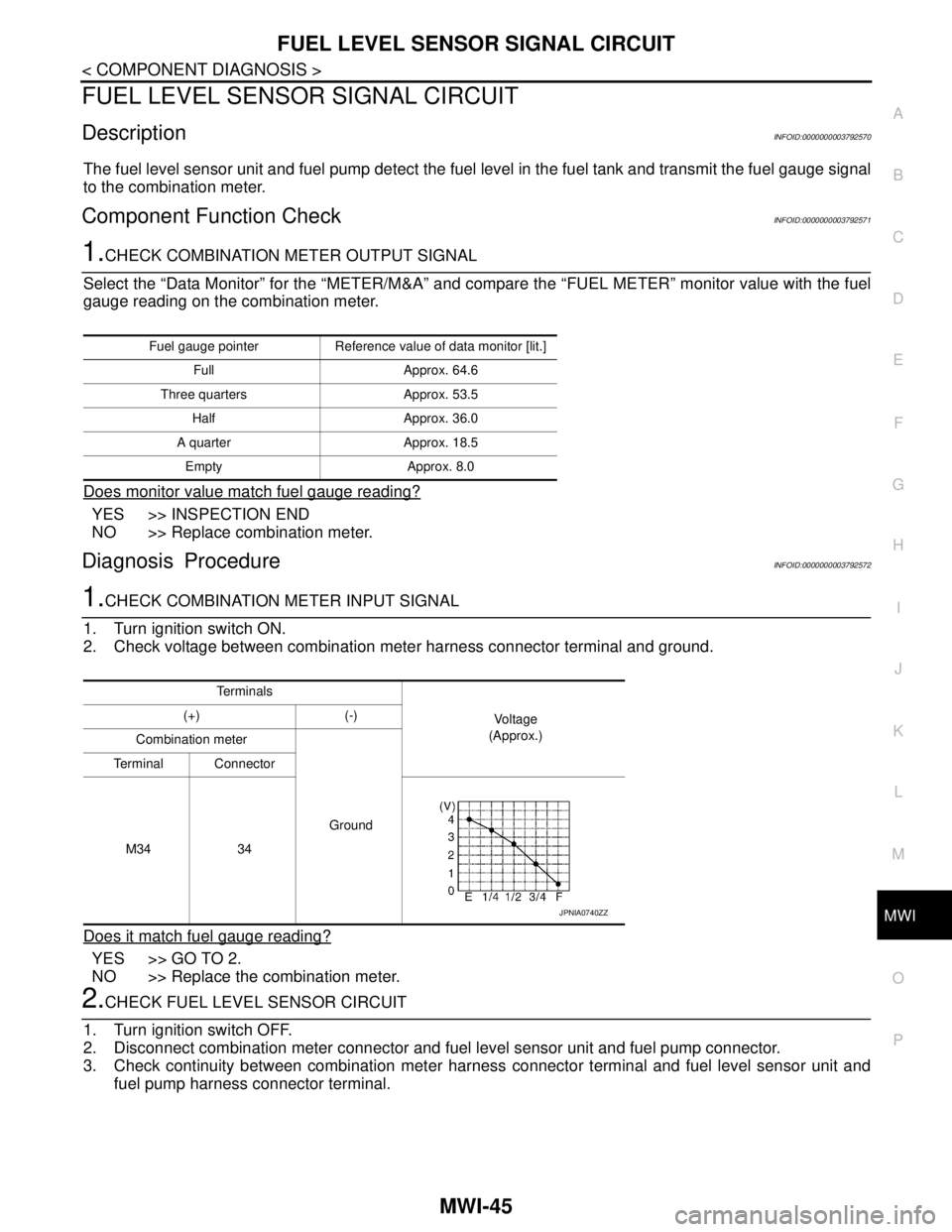
1.CHECK COMBINATION METER OUTPUT SIGNAL
Select the “Data Monitor” for the “METER/M&A” and compare the “FUEL METER” monitor value with the fuel
gauge reading on the combination meter.
Does monitor value match fuel gauge reading?
YES >> INSPECTION END
NO >> Replace combination meter.
Diagnosis ProcedureINFOID:0000000003792572
1.CHECK COMBINATION METER INPUT SIGNAL
1. Turn ignition switch ON.
2. Check voltage between combination meter harness connector terminal and ground.
Does it match fuel gauge reading?
YES >> GO TO 2.
NO >> Replace the combination meter.
2.CHECK FUEL LEVEL SENSOR CIRCUIT
1. Turn ignition switch OFF.
2. Disconnect combination meter connector and fuel level sensor unit and fuel pump connector.
3. Check continuity between combination meter harness connector terminal and fuel level sensor unit and
fuel pump harness connector terminal.
Fuel gauge pointer Reference value of data monitor [lit.]
Full Approx. 64.6
Three quarters Approx. 53.5
Half Approx. 36.0
A quarter Approx. 18.5
Empty Approx. 8.0
Te r m i n a l s
Vo l ta g e
(Approx.) (+) (-)
Combination meter
Ground Terminal Connector
M34 34
JPNIA0740ZZ
Page 3300 of 5121

MWI-46
< COMPONENT DIAGNOSIS >
FUEL LEVEL SENSOR SIGNAL CIRCUIT
4. Check continuity between combination meter harness connector terminal and ground.
Is the inspection result normal?
YES >> GO TO 3.
NO >> Repair harness or connector.
3.CHECK FUEL LEVEL SENSOR GROUND CIRCUIT
Check continuity between fuel level sensor unit and fuel pump harness connector terminal and combination
meter harness connector terminal.
Is the inspection result normal?
YES >> INSPECTION END
NO >> Repair harness or connector.
Component InspectionINFOID:0000000003792573
1.REMOVE FUEL LEVEL SENSOR UNIT
Remove the fuel level sensor unit. Refer to FL-5, "
Removal and Installation".
>> GO TO 2.
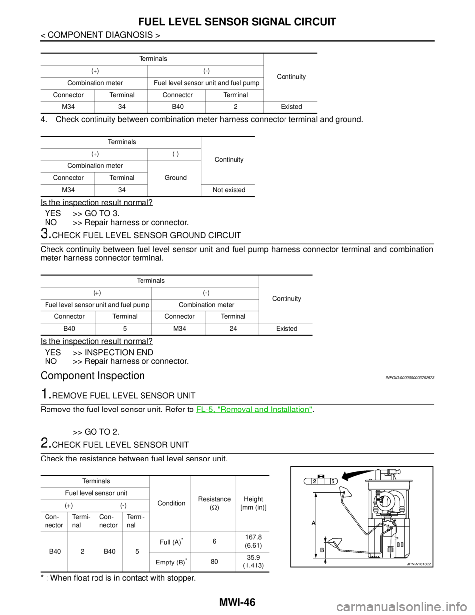
2.CHECK FUEL LEVEL SENSOR UNIT
Check the resistance between fuel level sensor unit.
* : When float rod is in contact with stopper.
Te r m i n a l s
Continuity (+) (-)
Combination meter Fuel level sensor unit and fuel pump
Connector Terminal Connector Terminal
M34 34 B40 2 Existed
Te r m i n a l s
Continuity (+) (-)
Combination meter
Ground Connector Terminal
M34 34 Not existed
Te r m i n a l s
Continuity (+) (-)
Fuel level sensor unit and fuel pump Combination meter
Connector Terminal Connector Terminal
B40 5 M34 24 Existed
Te r m i n a l s
ConditionResistance
(Ω)Height
[mm (in)] Fuel level sensor unit
(+) (-)
Con-
nectorTe r m i -
nalCon-
nectorTe r m i -
nal
B402B405Full (A)
*6167.8
(6.61)
Empty (B)
*8035.9
(1.413)JPNIA1018ZZ
Page 3301 of 5121
MWI
FUEL LEVEL SENSOR SIGNAL CIRCUIT
MWI-47
< COMPONENT DIAGNOSIS >
C
D
E
F
G
H
I
J
K
L
MB A
O
P
Is the inspection result normal?
YES >> INSPECTION END
NO >> Replace fuel level sensor unit.
Page 3310 of 5121

MWI-56
< ECU DIAGNOSIS >
COMBINATION METER
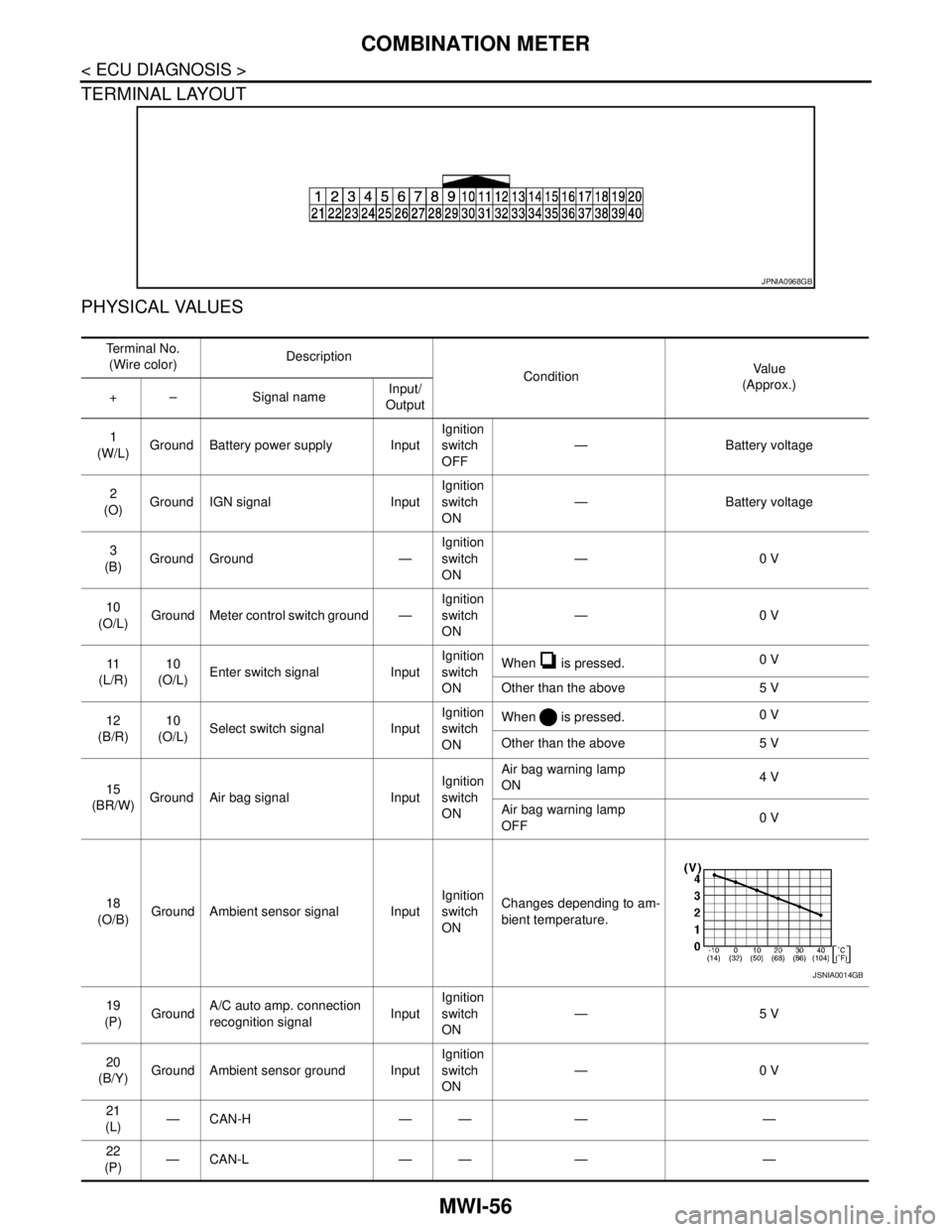
TERMINAL LAYOUT
PHYSICAL VALUES
JPNIA0968GB
Te r m i n a l N o .
(Wire color)Description
ConditionVa l u e
(Approx.)
+ – Signal nameInput/
Output
1
(W/L)Ground Battery power supply InputIgnition
switch
OFF— Battery voltage
2
(O)Ground IGN signal InputIgnition
switch
ON— Battery voltage
3
(B)Ground Ground —Ignition
switch
ON—0 V
10
(O/L)Ground Meter control switch ground —Ignition
switch
ON—0 V
11
(L/R)10
(O/L)Enter switch signal InputIgnition
switch
ONWhen is pressed.0 V
Other than the above 5 V
12
(B/R)10
(O/L)Select switch signal InputIgnition
switch
ONWhen is pressed.0 V
Other than the above 5 V
15
(BR/W)Ground Air bag signal InputIgnition
switch
ONAir bag warning lamp
ON4 V
Air bag warning lamp
OFF0 V
18
(O/B)Ground Ambient sensor signal InputIgnition
switch
ONChanges depending to am-
bient temperature.
19
(P)GroundA/C auto amp. connection
recognition signalInputIgnition
switch
ON—5 V
20
(B/Y)Ground Ambient sensor ground InputIgnition
switch
ON—0 V
21
(L)—CAN-H — — — —
22
(P)—CAN-L — — — —
JSNIA0014GB
Page 3311 of 5121

MWI
COMBINATION METER
MWI-57
< ECU DIAGNOSIS >
C
D
E
F
G
H
I
J
K
L
MB A
O
P
23
(B)Ground Ground —Ignition
switch
ON—0 V
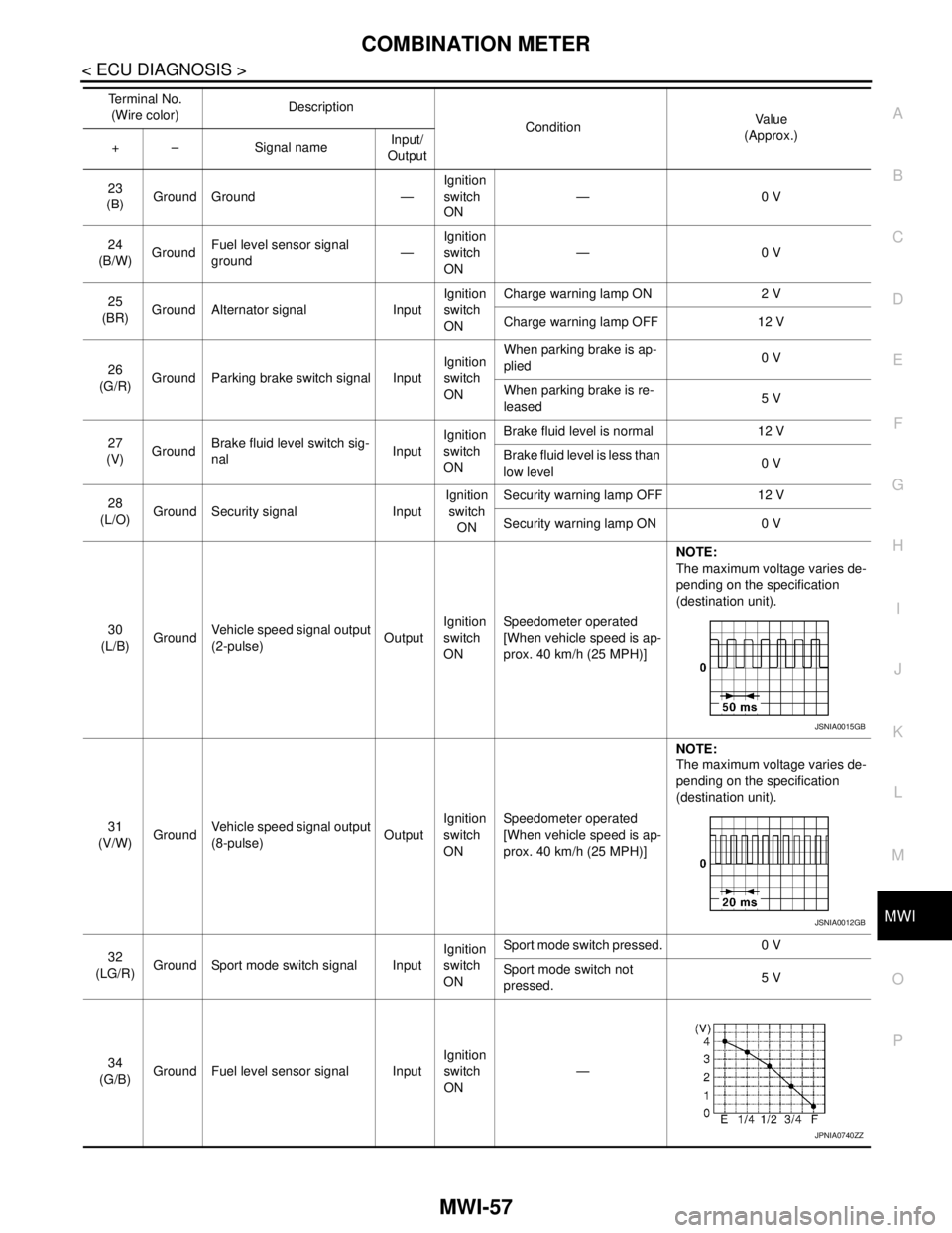
24
(B/W)GroundFuel level sensor signal
ground—Ignition
switch
ON—0 V
25
(BR)Ground Alternator signal InputIgnition
switch
ONCharge warning lamp ON 2 V
Charge warning lamp OFF 12 V
26
(G/R)Ground Parking brake switch signal InputIgnition
switch
ONWhen parking brake is ap-
plied0 V
When parking brake is re-
leased5 V
27
(V)GroundBrake fluid level switch sig-
nalInputIgnition
switch
ONBrake fluid level is normal 12 V
Brake fluid level is less than
low level0 V
28
(L/O)Ground Security signal InputIgnition
switch
ONSecurity warning lamp OFF 12 V
Security warning lamp ON 0 V
30
(L/B)GroundVehicle speed signal output
(2-pulse)OutputIgnition
switch
ONSpeedometer operated
[When vehicle speed is ap-
prox. 40 km/h (25 MPH)]NOTE:
The maximum voltage varies de-
pending on the specification
(destination unit).
31
(V/W)GroundVehicle speed signal output
(8-pulse)OutputIgnition
switch
ONSpeedometer operated
[When vehicle speed is ap-
prox. 40 km/h (25 MPH)]NOTE:
The maximum voltage varies de-
pending on the specification
(destination unit).
32
(LG/R)Ground Sport mode switch signal InputIgnition
switch
ONSport mode switch pressed. 0 V
Sport mode switch not
pressed.5 V
34
(G/B)Ground Fuel level sensor signal InputIgnition
switch
ON— Te r m i n a l N o .
(Wire color)Description
ConditionVa l u e
(Approx.)
+ – Signal nameInput/
Output
JSNIA0015GB
JSNIA0012GB
JPNIA0740ZZ
Page 3323 of 5121

MWI
BCM (BODY CONTROL MODULE)
MWI-69
< ECU DIAGNOSIS >
C
D
E
F
G
H
I
J
K
L
MB A
O
P
DOOR SW-BKNOTE:
The item is indicated, but not monitored. Off
CDL LOCK SWOther than power door lock switch LOCK Off
Power door lock switch LOCK On
CDL UNLOCK SWOther than power door lock switch UNLOCK Off
Power door lock switch UNLOCK On
KEY CYL LK-SWNOTE:
The item is indicated, but not monitored. Off
KEY CYL UN-SWNOTE:
The item is indicated, but not monitored. Off
KEY CYL SW-TRNOTE:
The item is indicated, but not monitored. Off
HAZARD SWHazard switch is OFF Off
Hazard switch is ON On
REAR DEF SW
NOTE:
At model with BOSE au-
dio system this item is in-
dicated, but is not
monitored.Rear window defogger switch is OFF Off
Rear window defogger switch is ON On
TR CANCEL SWNOTE:
The item is indicated, but not monitored. Off
TR/BD OPEN SWTrunk lid opener switch OFF Off
While the trunk lid opener switch is turned ON On
TRNK/HAT MNTRTrunk lid closed Off
Trunk lid opened On
RKE-LOCKLOCK button of the key is not pressed Off
LOCK button of the key is pressed On
RKE-UNLOCKUNLOCK button of the key is not pressed Off
UNLOCK button of the key is pressed On
RKE-TR/BDTRUNK OPEN button of the key is not pressed Off
TRUNK OPEN button of the key is pressed On
RKE-PANICNOTE:
The item is indicated, but not monitored. Off
RKE-P/W OPENNOTE:
The item is indicated, but not monitored. Off
RKE-MODE CHGLOCK/UNLOCK button of the key is not pressed and held simulta-
neouslyOff
LOCK/UNLOCK button of the key is pressed and held simulta-
neouslyOn
OPTICAL SENSORBright outside of the vehicle Close to 5 V
Dark outside of the vehicle Close to 0 V
REQ SW -DRDriver door request switch is not pressed Off
Driver door request switch is pressed On
REQ SW -ASPassenger door request switch is not pressed Off
Passenger door request switch is pressed On
REQ SW -RRNOTE:
The item is indicated, but not monitored. Off Monitor Item Condition Value/Status