2008 NISSAN TEANA sensor
[x] Cancel search: sensorPage 3341 of 5121
MWI
BCM (BODY CONTROL MODULE)
MWI-87
< ECU DIAGNOSIS >
C
D
E
F
G
H
I
J
K
L
MB A
O
P
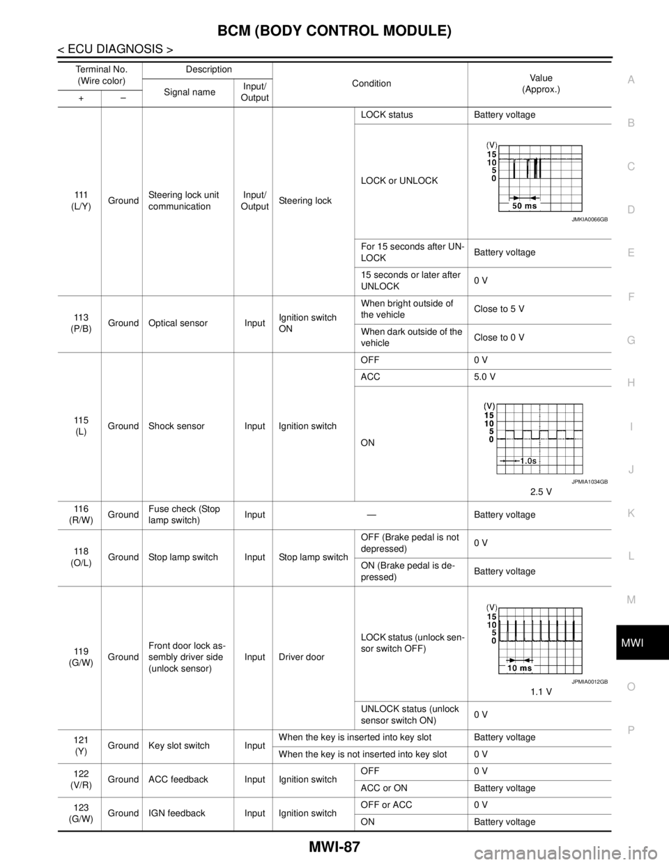
111
(L/Y)GroundSteering lock unit
communicationInput/
OutputSteering lockLOCK status Battery voltage
LOCK or UNLOCK
For 15 seconds after UN-
LOCKBattery voltage
15 seconds or later after
UNLOCK0 V
11 3
(P/B)Ground Optical sensor InputIgnition switch
ONWhen bright outside of
the vehicleClose to 5 V
When dark outside of the
vehicleClose to 0 V
11 5
(L)Ground Shock sensor Input Ignition switchOFF 0 V
ACC 5.0 V
ON
2.5 V
11 6
(R/W)GroundFuse check (Stop
lamp switch)Input — Battery voltage
11 8
(O/L)Ground Stop lamp switch Input Stop lamp switchOFF (Brake pedal is not
depressed)0 V
ON (Brake pedal is de-
pressed)Battery voltage
11 9
(G/W)GroundFront door lock as-
sembly driver side
(unlock sensor)Input Driver doorLOCK status (unlock sen-
sor switch OFF)
1.1 V
UNLOCK status (unlock
sensor switch ON)0 V
121
(Y)Ground Key slot switch InputWhen the key is inserted into key slot Battery voltage
When the key is not inserted into key slot 0 V
122
(V/R)Ground ACC feedback Input Ignition switchOFF 0 V
ACC or ON Battery voltage
123
(G/W)Ground IGN feedback Input Ignition switchOFF or ACC 0 V
ON Battery voltage Te r m i n a l N o .
(Wire color)Description
ConditionVa l u e
(Approx.)
Signal nameInput/
Output +–
JMKIA0066GB
JPMIA1034GB
JPMIA0012GB
Page 3359 of 5121
MWI
IPDM E/R (INTELLIGENT POWER DISTRIBUTION MODULE ENGINE ROOM)
MWI-105
< ECU DIAGNOSIS >
C
D
E
F
G
H
I
J
K
L
MB A
O
P
11
(P)GroundSteering lock unit power
supplyOutputIgnition
switch
OFFA few seconds after open-
ing the driver doorBattery voltage
Ignition
switch
LOCKPress the push-button ig-
nition switchBattery voltage
Ignition switch ACC or ON 0 V
12
(B/W)Ground Ground — Ignition switch ON 0 V
13
(SB)Ground Fuel pump power supply OutputApproximately 1 second or more after
turning the ignition switch ON0 V
Approximately 1 second after turning
the ignition switch ON
Engine runningBattery voltage
15
(W)Ground Ignition relay power supply OutputIgnition switch OFF 0 V
Ignition switch ON Battery voltage
16
(R)Ground Front wiper auto stop InputIgnition
switch ONFront wiper stop position 0 V
Any position other than
front wiper stop positionBattery voltage
17
(V)GroundHeadlamp washer relay
controlInputIgnition
switch ONHeadlamp washer deacti-
vatedBattery voltage
Headlamp washer activat-
ed0 V
19
(Y)Ground Ignition relay power supply OutputIgnition switch OFF 0 V
Ignition switch ON Battery voltage
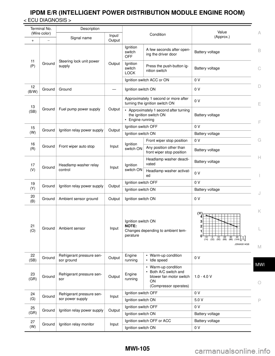
20
(B)Ground Ambient sensor ground Output Ignition switch ON 0 V
21
(O)Ground Ambient sensor InputIgnition switch ON
NOTE:
Changes depending to ambient tem-
perature
22
(SB)GroundRefrigerant pressure sen-
sor groundOutputEngine
running Warm-up condition
Idle speed0 V
23
(GR)GroundRefrigerant pressure sen-
sorOutputEngine
running Warm-up condition
Both A/C switch and
blower fan motor switch
ON
(Compressor operates)1.0 - 4.0 V
24
(G)
GroundRefrigerant pressure sen-
sor power supplyInputIgnition switch OFF 0 V
Ignition switch ON 5.0 V
25
(GR)Ground Ignition relay power supply OutputIgnition switch OFF 0 V
Ignition switch ON Battery voltage
27
(W)Ground Ignition relay monitor InputIgnition switch OFF or ACC Battery voltage
Ignition switch ON 0 V Te r m i n a l N o .
(Wire color)Description
ConditionVa l u e
(Approx.)
Signal nameInput/
Output +−
JSNIA0014GB
Page 3363 of 5121
MWI
IPDM E/R (INTELLIGENT POWER DISTRIBUTION MODULE ENGINE ROOM)
MWI-109
< ECU DIAGNOSIS >
C
D
E
F
G
H
I
J
K
L
MB A
O
P
88
(P)GroundWasher pump power sup-
plyOutput Ignition switch ON Battery voltage
89
(W)Ground Headlamp HI (RH) OutputIgnition
switch ON Lighting switch HI
Lighting switch PASSBattery voltage
Lighting switch OFF 0 V
90
(O)Ground Headlamp HI (LH) OutputIgnition
switch ON Lighting switch HI
Lighting switch PASSBattery voltage
Lighting switch OFF 0 V
91
(O)Ground Parking lamp (RH) OutputIgnition
switch ONLighting switch 1ST Battery voltage
Lighting switch OFF 0 V
92
(L)Ground Parking lamp (LH) OutputIgnition
switch ONLighting switch 1ST Battery voltage
Lighting switch OFF 0 V
93
(BR)GroundHeadlamp aiming motor
(RH)OutputIgnition
switch ONLighting switch 1ST Battery voltage
Lighting switch OFF 0 V
94
(Y)GroundHeadlamp aiming motor
(LH)OutputIgnition
switch ONLighting switch 1ST Battery voltage
Lighting switch OFF 0 V
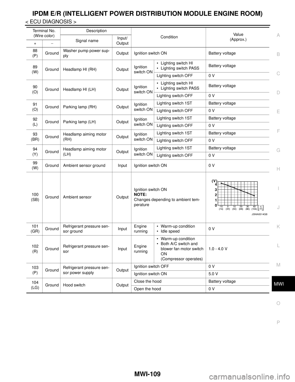
99
(W)Ground Ambient sensor ground Input Ignition switch ON 0 V
100
(SB)Ground Ambient sensor OutputIgnition switch ON
NOTE:
Changes depending to ambient tem-
perature
101
(GR)GroundRefrigerant pressure sen-
sor groundInputEngine
running Warm-up condition
Idle speed0 V
102
(R)GroundRefrigerant pressure sen-
sorInputEngine
running Warm-up condition
Both A/C switch and
blower fan motor switch
ON
(Compressor operates)1.0 - 4.0 V
103
(P)GroundRefrigerant pressure sen-
sor power supplyOutputIgnition switch OFF 0 V
Ignition switch ON 5.0 V
104
(LG)
Ground Hood switch OutputClose the hood Battery voltage
Open the hood 0 V Te r m i n a l N o .
(Wire color)Description
ConditionVa l u e
(Approx.)
Signal nameInput/
Output +−
JSNIA0014GB
Page 3370 of 5121
MWI-116
< SYMPTOM DIAGNOSIS >
THE FUEL GAUGE POINTER DOES NOT MOVE
SYMPTOM DIAGNOSIS
THE FUEL GAUGE POINTER DOES NOT MOVE
DescriptionINFOID:0000000003792601
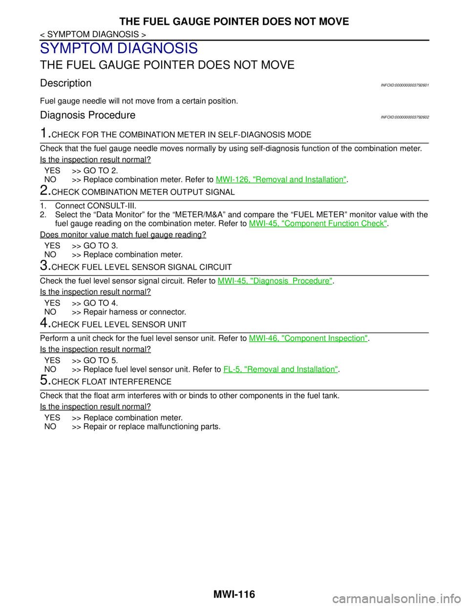
Fuel gauge needle will not move from a certain position.
Diagnosis ProcedureINFOID:0000000003792602
1.CHECK FOR THE COMBINATION METER IN SELF-DIAGNOSIS MODE
Check that the fuel gauge needle moves normally by using self-diagnosis function of the combination meter.
Is the inspection result normal?
YES >> GO TO 2.
NO >> Replace combination meter. Refer to MWI-126, "
Removal and Installation".
2.CHECK COMBINATION METER OUTPUT SIGNAL
1. Connect CONSULT-III.
2. Select the “Data Monitor” for the “METER/M&A” and compare the “FUEL METER” monitor value with the
fuel gauge reading on the combination meter. Refer to MWI-45, "
Component Function Check".
Does monitor value match fuel gauge reading?
YES >> GO TO 3.
NO >> Replace combination meter.
3.CHECK FUEL LEVEL SENSOR SIGNAL CIRCUIT
Check the fuel level sensor signal circuit. Refer to MWI-45, "
DiagnosisProcedure".
Is the inspection result normal?
YES >> GO TO 4.
NO >> Repair harness or connector.
4.CHECK FUEL LEVEL SENSOR UNIT
Perform a unit check for the fuel level sensor unit. Refer to MWI-46, "
Component Inspection".
Is the inspection result normal?
YES >> GO TO 5.
NO >> Replace fuel level sensor unit. Refer to FL-5, "
Removal and Installation".
5.CHECK FLOAT INTERFERENCE
Check that the float arm interferes with or binds to other components in the fuel tank.
Is the inspection result normal?
YES >> Replace combination meter.
NO >> Repair or replace malfunctioning parts.
Page 3377 of 5121
MWI
THE AMBIENT TEMPERATURE DISPLAY IS INCORRECT
MWI-123
< SYMPTOM DIAGNOSIS >
C
D
E
F
G
H
I
J
K
L
MB A
O
P
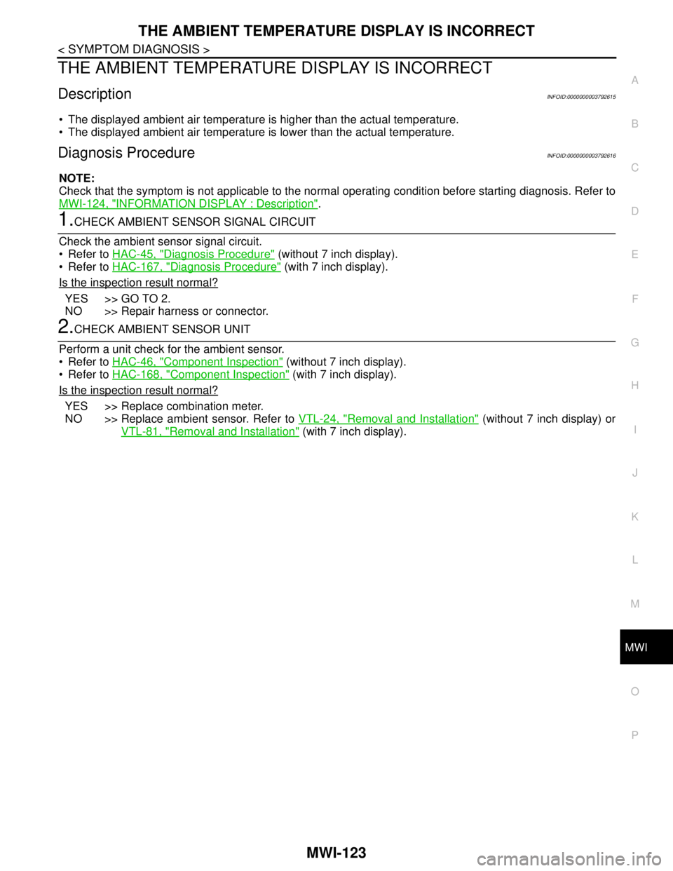
THE AMBIENT TEMPERATURE DISPLAY IS INCORRECT
DescriptionINFOID:0000000003792615
The displayed ambient air temperature is higher than the actual temperature.
The displayed ambient air temperature is lower than the actual temperature.
Diagnosis ProcedureINFOID:0000000003792616
NOTE:
Check that the symptom is not applicable to the normal operating condition before starting diagnosis. Refer to
MWI-124, "
INFORMATION DISPLAY : Description".
1.CHECK AMBIENT SENSOR SIGNAL CIRCUIT
Check the ambient sensor signal circuit.
Refer to HAC-45, "
Diagnosis Procedure" (without 7 inch display).
Refer to HAC-167, "
Diagnosis Procedure" (with 7 inch display).
Is the inspection result normal?
YES >> GO TO 2.
NO >> Repair harness or connector.
2.CHECK AMBIENT SENSOR UNIT
Perform a unit check for the ambient sensor.
Refer to HAC-46, "
Component Inspection" (without 7 inch display).
Refer to HAC-168, "
Component Inspection" (with 7 inch display).
Is the inspection result normal?
YES >> Replace combination meter.
NO >> Replace ambient sensor. Refer to VTL-24, "
Removal and Installation" (without 7 inch display) or
VTL-81, "
Removal and Installation" (with 7 inch display).
Page 3378 of 5121

MWI-124
< SYMPTOM DIAGNOSIS >
NORMAL OPERATING CONDITION
NORMAL OPERATING CONDITION
INFORMATION DISPLAY
INFORMATION DISPLAY : DescriptionINFOID:0000000003792618
AMBIENT AIR TEMPERATURE
The displayed ambient air temperature on the information display may differ from the actual temperature
because it is a corrected value calculated from the ambient sensor signal by the combination meter. Refer to
MWI-27, "
INFORMATION DISPLAY : System Description" for details on the correction process.
POSSIBLE DRIVING DISTANCE
The calculated possible driving distance may differ from the actual distance to empty if the refueling amount is
approximately 15 (3-3/10 Imp gal) or less. This is because the refuel control (moves the fuel gauge needle
quicker than normal judging that the driver is refueling the vehicle) is not performing.
Page 3395 of 5121
![NISSAN TEANA 2008 Service Manual PCS-4
< FUNCTION DIAGNOSIS >[IPDM E/R]
RELAY CONTROL SYSTEM
FUNCTION DIAGNOSIS
RELAY CONTROL SYSTEM
System DiagramINFOID:0000000003773255
System DescriptionINFOID:0000000003773256
IPDM E/R activates t NISSAN TEANA 2008 Service Manual PCS-4
< FUNCTION DIAGNOSIS >[IPDM E/R]
RELAY CONTROL SYSTEM
FUNCTION DIAGNOSIS
RELAY CONTROL SYSTEM
System DiagramINFOID:0000000003773255
System DescriptionINFOID:0000000003773256
IPDM E/R activates t](/manual-img/5/57391/w960_57391-3394.png)
PCS-4
< FUNCTION DIAGNOSIS >[IPDM E/R]
RELAY CONTROL SYSTEM
FUNCTION DIAGNOSIS
RELAY CONTROL SYSTEM
System DiagramINFOID:0000000003773255
System DescriptionINFOID:0000000003773256
IPDM E/R activates the internal control circuit to perform the relay ON-OFF control according to the input sig-
nals from various sensors and the request signals received from control units via CAN communication.
CAUTION:
IPDM E/R integrated relays cannot be removed.
JPMIA1015GB
Page 3414 of 5121
![NISSAN TEANA 2008 Service Manual PCS
IPDM E/R (INTELLIGENT POWER DISTRIBUTION MODULE ENGINE ROOM)
PCS-23
< ECU DIAGNOSIS >[IPDM E/R]
C
D
E
F
G
H
I
J
K
L B A
O
P N
11
(P)GroundSteering lock unit power
supplyOutputIgnition
switch
OF NISSAN TEANA 2008 Service Manual PCS
IPDM E/R (INTELLIGENT POWER DISTRIBUTION MODULE ENGINE ROOM)
PCS-23
< ECU DIAGNOSIS >[IPDM E/R]
C
D
E
F
G
H
I
J
K
L B A
O
P N
11
(P)GroundSteering lock unit power
supplyOutputIgnition
switch
OF](/manual-img/5/57391/w960_57391-3413.png)
PCS
IPDM E/R (INTELLIGENT POWER DISTRIBUTION MODULE ENGINE ROOM)
PCS-23
< ECU DIAGNOSIS >[IPDM E/R]
C
D
E
F
G
H
I
J
K
L B A
O
P N
11
(P)GroundSteering lock unit power
supplyOutputIgnition
switch
OFFA few seconds after open-
ing the driver doorBattery voltage
Ignition
switch
LOCKPress the push-button ig-
nition switchBattery voltage
Ignition switch ACC or ON 0 V
12
(B/W)Ground Ground — Ignition switch ON 0 V
13
(SB)Ground Fuel pump power supply OutputApproximately 1 second or more after
turning the ignition switch ON0 V
Approximately 1 second after turning
the ignition switch ON
Engine runningBattery voltage
15
(W)Ground Ignition relay power supply OutputIgnition switch OFF 0 V
Ignition switch ON Battery voltage
16
(R)Ground Front wiper auto stop InputIgnition
switch ONFront wiper stop position 0 V
Any position other than
front wiper stop positionBattery voltage
17
(V)GroundHeadlamp washer relay
controlInputIgnition
switch ONHeadlamp washer deacti-
vatedBattery voltage
Headlamp washer activat-
ed0 V
19
(Y)Ground Ignition relay power supply OutputIgnition switch OFF 0 V
Ignition switch ON Battery voltage
20
(B)Ground Ambient sensor ground Output Ignition switch ON 0 V
21
(O)Ground Ambient sensor InputIgnition switch ON
NOTE:
Changes depending to ambient tem-
perature
22
(SB)GroundRefrigerant pressure sen-
sor groundOutputEngine
running Warm-up condition
Idle speed0 V
23
(GR)GroundRefrigerant pressure sen-
sorOutputEngine
running Warm-up condition
Both A/C switch and
blower fan motor switch
ON
(Compressor operates)1.0 - 4.0 V
24
(G)
GroundRefrigerant pressure sen-
sor power supplyInputIgnition switch OFF 0 V
Ignition switch ON 5.0 V
25
(GR)Ground Ignition relay power supply OutputIgnition switch OFF 0 V
Ignition switch ON Battery voltage
27
(W)Ground Ignition relay monitor InputIgnition switch OFF or ACC Battery voltage
Ignition switch ON 0 V Te r m i n a l N o .
(Wire color)Description
ConditionVa l u e
(Approx.)
Signal nameInput/
Output +−
JSNIA0014GB