2008 NISSAN TEANA relay
[x] Cancel search: relayPage 1155 of 5121
REAR WINDOW DEFOGGER SYSTEM
DEF-5
< FUNCTION DIAGNOSIS >
C
D
E
F
G
H
I
J
K
MA
B
DEF
N
O
P
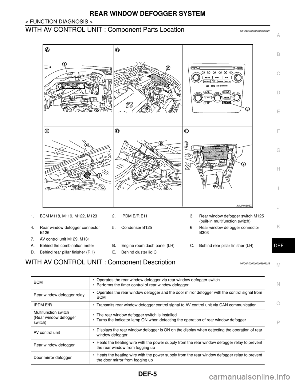
WITH AV CONTROL UNIT : Component Parts LocationINFOID:0000000003806027
WITH AV CONTROL UNIT : Component DescriptionINFOID:0000000003806028
1. BCM M118, M119, M122, M123 2. IPDM E/R E11 3. Rear window defogger switch M125
(built-in multifunction switch)
4. Rear window defogger connector
B1265. Condenser B125 6. Rear window defogger connector
B303
7. AV control unit M129, M131
A. Behind the combination meter B. Engine room dash panel (LH) C. Behind rear pillar finisher (LH)
D. Behind rear pillar finisher (RH) E. Behind cluster lid C
JMLIA0150ZZ
BCM Operates the rear window defogger via rear window defogger switch
Performs the timer control of rear window defogger
Rear window defogger relay Operates the rear window defogger and the door mirror defogger with the control signal from
BCM
IPDM E/R Transmits rear window defogger control signal to AV control unit via CAN communication
Multifunction switch
(Rear window defogger
switch) The rear window defogger switch is installed
Turns the indicator lamp ON when detecting the operation of rear window defogger
AV control unit Displays the rear window defogger is ON on the display when detecting the operation of rear
window defogger
Rear window defogger Heats the heating wire with the power supply from the rear window defogger relay to prevent
the rear window from fogging up
Door mirror defogger Heats the heating wire with the power supply from the rear window defogger relay to prevent
the door mirror from fogging up
Page 1156 of 5121
DEF-6
< FUNCTION DIAGNOSIS >
REAR WINDOW DEFOGGER SYSTEM
WITHOUT AV CONTROL UNIT
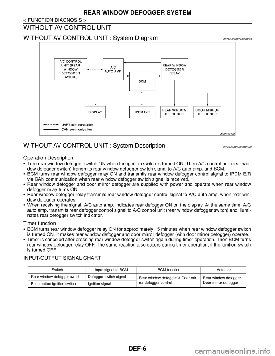
WITHOUT AV CONTROL UNIT : System DiagramINFOID:0000000003806029
WITHOUT AV CONTROL UNIT : System DescriptionINFOID:0000000003806030
Operation Description
Turn rear window defogger switch ON when the ignition switch is turned ON. Then A/C control unit (rear win-
dow defogger switch) transmits rear window defogger switch signal to A/C auto amp. and BCM.
BCM turns rear window defogger relay ON and transmits rear window defogger control signal to IPDM E/R
via CAN communication when rear window defogger switch signal is received.
Rear window defogger and door mirror defogger are supplied with power and operate when rear window
defogger relay turns ON.
Rear window defogger relay transmits rear window defogger control signal to A/C auto amp. when rear win-
dow defogger operates.
When receiving the signal, A/C auto amp. indicates rear defogger ON on the display. At the same time, A/C
auto amp. transmits rear defogger control signal to A/C control unit (rear window defogger switch) and illumi-
nates rear defogger switch indicator.
Timer function
BCM turns rear window defogger relay ON for approximately 15 minutes when rear window defogger switch
is turned ON. It makes rear window defogger and door mirror defogger (with door mirror defogger) operate.
Timer is canceled after pressing rear window defogger switch again during timer operation. Then BCM turns
rear window defogger relay OFF. The same reaction also occurs during timer operation, if the ignition switch
is turned OFF.
INPUT/OUTPUT SIGNAL CHART
JMLIA0154GB
Switch Input signal to BCM BCM function Actuator
Rear window defogger switch Defogger switch signal
Rear window defogger & Door mir-
ror defogger controlRear window defogger
Door mirror defogger
Push button ignition switch Ignition signal
Page 1157 of 5121
REAR WINDOW DEFOGGER SYSTEM
DEF-7
< FUNCTION DIAGNOSIS >
C
D
E
F
G
H
I
J
K
MA
B
DEF
N
O
P
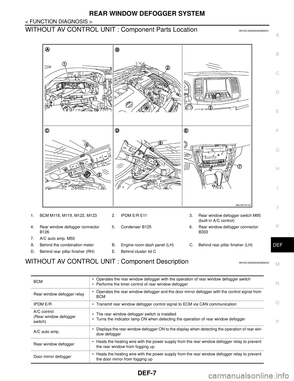
WITHOUT AV CONTROL UNIT : Component Parts LocationINFOID:0000000003806031
WITHOUT AV CONTROL UNIT : Component DescriptionINFOID:0000000003806032
1. BCM M118, M119, M122, M123 2. IPDM E/R E11 3. Rear window defogger switch M95
(built-in A/C control)
4. Rear window defogger connector
B1265. Condenser B125 6. Rear window defogger connector
B303
7. A/C auto amp. M50
A. Behind the combination meter B. Engine room dash panel (LH) C. Behind rear pillar finisher (LH)
D. Behind rear pillar finisher (RH) E. Behind cluster lid C
JMLIA0151ZZ
BCM Operates the rear window defogger with the operation of rear window defogger switch
Performs the timer control of rear window defogger
Rear window defogger relay Operates the rear window defogger and the door mirror defogger with the control signal from
BCM
IPDM E/R Transmit rear window defogger control signal to ECM via CAN communication
A/C control
(Rear window defogger
switch) The rear window defogger switch is installed
Turns the indicator lamp ON when detecting the operation of rear window defogger
A/C auto amp. Displays the rear window defogger ON to the display when detecting the operation of rear win-
dow defogger
Rear window defogger Heats the heating wire with the power supply from the rear window defogger relay to prevent
the rear window from fogging up
Door mirror defogger Heats the heating wire with the power supply from the rear window defogger relay to prevent
the door mirror from fogging up
Page 1164 of 5121
DEF-14
< COMPONENT DIAGNOSIS >
REAR WINDOW DEFOGGER RELAY
REAR WINDOW DEFOGGER RELAY
DescriptionINFOID:0000000003857611
Power is supplied to the rear window defogger with BCM control.
Component Function CheckINFOID:0000000003857612
1.CHECK FUNCTION
1. Perform Active Test (“REAR DEFOGGER”) with CONSULT-III.
2. Touch “ON”.
3. Check that the rear window heating wire is getting warmer.
Is the inspection result normal?
YES >> Rear window defogger relay power supply circuit function is OK.
NO >> Refer to DEF-14, "
Diagnosis Procedure"
Diagnosis ProcedureINFOID:0000000003857613
1.CHECK FUSE
1. Turn ignition switch OFF.
2. Check 10A fuse [No.3, located in fuse block (J/B)].
Is the inspection result normal?
YES >> GO TO 2.
NO >> Replace the blown fuse after repairing the affected circuit if a fuse is blown.
2.CHECK REAR WINDOW DEFOGGER RELAY CIRCUIT 1
1. Turn ignition switch ON.
2. Check voltage between BCM harness connector and ground.
Is the inspection result normal?
YES >> Rear window defogger relay power supply circuit is OK.
NO >> GO TO 3.
3.CHECK REAR WINDOW DEFOGGER RELAY CIRCUIT 2
1. Turn ignition switch OFF.
2. Disconnect BCM connector and fuse block (J/B).
3. Check continuity between BCM harness connector and fuse block (J/B) harness connector.
4. Check continuity between BCM harness connector and ground.
Is the inspection result normal?
YES >> GO TO 4.
NO >> Repair or replace harness.
(+)
(–) ConditionVoltage (V)
(Approx.) BCM
Connector Terminal
M123 151 GroundRear window de-
fogger switchON 0
OFF Battery voltage
BCM Fuse block (J/B)
Continuity
Connector Terminal Connector Terminal
M123 151 M2 4B Existed
BCM
GroundContinuity
Connector Terminal
M123 151 Not existed
Page 1165 of 5121
REAR WINDOW DEFOGGER RELAY
DEF-15
< COMPONENT DIAGNOSIS >
C
D
E
F
G
H
I
J
K
MA
B
DEF
N
O
P
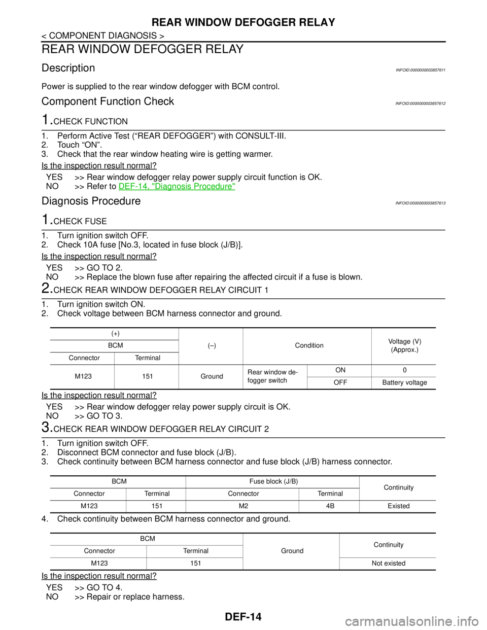
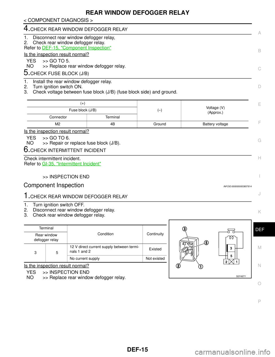
4.CHECK REAR WINDOW DEFOGGER RELAY
1. Disconnect rear window defogger relay,
2. Check rear window defogger relay.
Refer to DEF-15, "
Component Inspection"
Is the inspection result normal?
YES >> GO TO 5.
NO >> Replace rear window defogger relay.
5.CHECK FUSE BLOCK (J/B)
1. Install the rear window defogger relay.
2. Turn ignition switch ON.
3. Check voltage between fuse block (J/B) (fuse block side) and ground.
Is the inspection result normal?
YES >> GO TO 6.
NO >> Repair or replace fuse block (J/B).
6.CHECK INTERMITTENT INCIDENT
Check intermittent incident.
Refer to GI-35, "
Intermittent Incident"
>> INSPECTION END
Component InspectionINFOID:0000000003857614
1.CHECK REAR WINDOW DEFOGGER RELAY
1. Turn ignition switch OFF.
2. Disconnect rear window defogger relay.
3. Check rear window defogger relay.
Is the inspection result normal?
YES >> INSPECTION END
NO >> Replace rear window defogger relay.
(+)
(–)Voltage (V)
(Approx.) Fuse block (J/B)
Connector Terminal
M2 4B Ground Battery voltage
Te r m i n a l
Condition Continuity
Rear window
defogger relay
3512 V direct current supply between termi-
nals 1 and 2Existed
No current supply Not existed
SEF497Y
Page 1166 of 5121
DEF-16
< COMPONENT DIAGNOSIS >
REAR WINDOW DEFOGGER
REAR WINDOW DEFOGGER
DescriptionINFOID:0000000003857615
Heats the heating wire with the power supply from the rear window defogger relay to prevent the rear window
from fogging up.
Component Function CheckINFOID:0000000003857616
1.CHECK REAR WINDOW DEFOGGER
1. Perform Active Test (“REAR DEFOGGER”) with CONSULT-III.
2. Touch “ON”.
3. Check that the rear window heating wire is getting warmer.
Is the inspection result normal?
YES >> Rear window defogger is OK.
NO >> Refer to DEF-16, "
Diagnosis Procedure"
Diagnosis ProcedureINFOID:0000000003857617
1.CHECK FUSE
1. Turn ignition switch OFF.
2. Check 20A fuse [No.15, located in fuse block (J/B)].
Is the inspection result normal?
YES >> GO TO 2.
NO >> Replace the blown fuse after repairing the affected circuit if a fuse is blown.
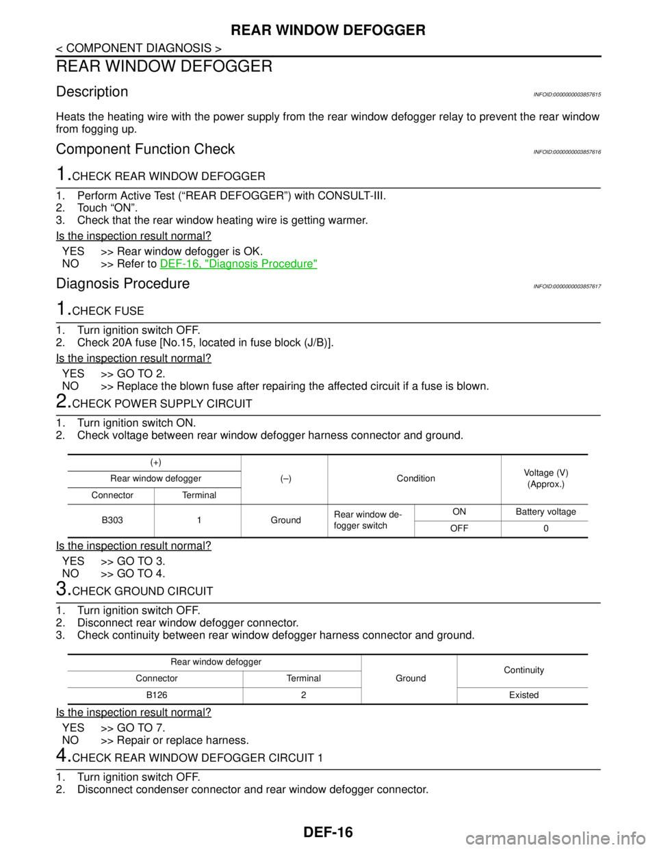
2.CHECK POWER SUPPLY CIRCUIT
1. Turn ignition switch ON.
2. Check voltage between rear window defogger harness connector and ground.
Is the inspection result normal?
YES >> GO TO 3.
NO >> GO TO 4.
3.CHECK GROUND CIRCUIT
1. Turn ignition switch OFF.
2. Disconnect rear window defogger connector.
3. Check continuity between rear window defogger harness connector and ground.
Is the inspection result normal?
YES >> GO TO 7.
NO >> Repair or replace harness.
4.CHECK REAR WINDOW DEFOGGER CIRCUIT 1
1. Turn ignition switch OFF.
2. Disconnect condenser connector and rear window defogger connector.
(+)
(–) Condition Voltage (V)
(Approx.) Rear window defogger
Connector Terminal
B303 1 GroundRear window de-
fogger switchON Battery voltage
OFF 0
Rear window defogger
GroundContinuity
Connector Terminal
B126 2 Existed
Page 1171 of 5121
DRIVER SIDE DOOR MIRROR DEFOGGER
DEF-21
< COMPONENT DIAGNOSIS >
C
D
E
F
G
H
I
J
K
MA
B
DEF
N
O
P
DRIVER SIDE DOOR MIRROR DEFOGGER
DescriptionINFOID:0000000003857622
Heats the heating wire with the power supply from the rear window defogger relay to prevent the door mirror
from fogging up.
Component Function CheckINFOID:0000000003857623
1.CHECK FUNCTION
1. Perform Active Test (“REAR DEFOGGER”) with CONSULT-III.
2. Touch “ON”.
3. Check that the driver side door mirror glass is getting warmer.
Is the inspection result normal?
YES >> Driver side door mirror defogger function is OK.
NO >> Refer to DEF-21, "
Diagnosis Procedure"
Diagnosis ProcedureINFOID:0000000003857624
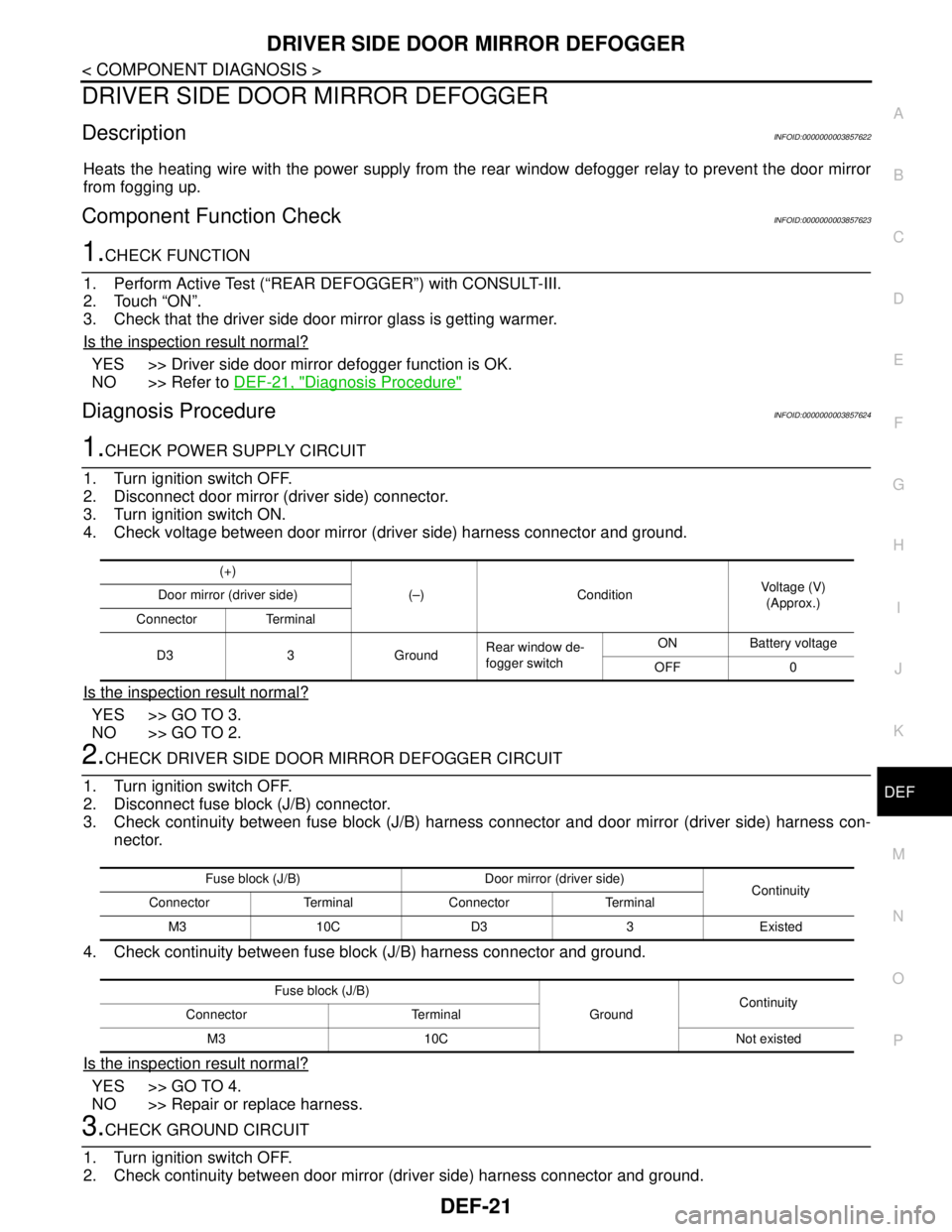
1.CHECK POWER SUPPLY CIRCUIT
1. Turn ignition switch OFF.
2. Disconnect door mirror (driver side) connector.
3. Turn ignition switch ON.
4. Check voltage between door mirror (driver side) harness connector and ground.
Is the inspection result normal?
YES >> GO TO 3.
NO >> GO TO 2.
2.CHECK DRIVER SIDE DOOR MIRROR DEFOGGER CIRCUIT
1. Turn ignition switch OFF.
2. Disconnect fuse block (J/B) connector.
3. Check continuity between fuse block (J/B) harness connector and door mirror (driver side) harness con-
nector.
4. Check continuity between fuse block (J/B) harness connector and ground.
Is the inspection result normal?
YES >> GO TO 4.
NO >> Repair or replace harness.
3.CHECK GROUND CIRCUIT
1. Turn ignition switch OFF.
2. Check continuity between door mirror (driver side) harness connector and ground.
(+)
(–) Condition Voltage (V)
(Approx.) Door mirror (driver side)
Connector Terminal
D3 3 GroundRear window de-
fogger switchON Battery voltage
OFF 0
Fuse block (J/B) Door mirror (driver side)
Continuity
Connector Terminal Connector Terminal
M3 10C D3 3 Existed
Fuse block (J/B)
GroundContinuity
Connector Terminal
M3 10C Not existed
Page 1173 of 5121
PASSENGER SIDE DOOR MIRROR DEFOGGER
DEF-23
< COMPONENT DIAGNOSIS >
C
D
E
F
G
H
I
J
K
MA
B
DEF
N
O
P
PASSENGER SIDE DOOR MIRROR DEFOGGER
DescriptionINFOID:0000000003857625
Heats the heating wire with the power supply from the rear window defogger relay to prevent the door mirror
from fogging up.
Component Function CheckINFOID:0000000003857626
1.CHECK FUNCTION
1. Perform Active Test (“REAR DEFOGGER”) with CONSULT-III.
2. Touch “ON”.
3. Check that the passenger side door mirror glass is getting warmer.
Is the inspection result normal?
YES >> Passenger side door mirror defogger function is OK.
NO >> Refer to DEF-23, "
Diagnosis Procedure"
Diagnosis ProcedureINFOID:0000000003857627
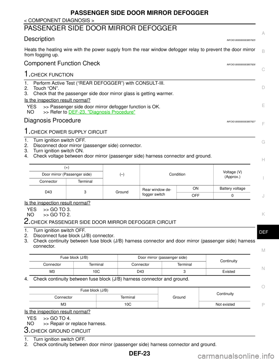
1.CHECK POWER SUPPLY CIRCUIT
1. Turn ignition switch OFF.
2. Disconnect door mirror (passenger side) connector.
3. Turn ignition switch ON.
4. Check voltage between door mirror (passenger side) harness connector and ground.
Is the inspection result normal?
YES >> GO TO 3.
NO >> GO TO 2.
2.CHECK PASSENGER SIDE DOOR MIRROR DEFOGGER CIRCUIT
1. Turn ignition switch OFF.
2. Disconnect fuse block (J/B) connector.
3. Check continuity between fuse block (J/B) harness connector and door mirror (passenger side) harness
connector.
4. Check continuity between fuse block (J/B) harness connector and ground.
Is the inspection result normal?
YES >> GO TO 4.
NO >> Repair or replace harness.
3.CHECK GROUND CIRCUIT
1. Turn ignition switch OFF.
2. Check continuity between door mirror (passenger side) harness connector and ground.
(+)
(–) ConditionVoltage (V)
(Approx.) Door mirror (Passenger side)
Connector Terminal
D43 3 GroundRear window de-
fogger switchON Battery voltage
OFF 0
Fuse block (J/B) Door mirror (passenger side)
Continuity
Connector Terminal Connector Terminal
M3 10C D43 3 Existed
Fuse block (J/B)
GroundContinuity
Connector Terminal
M3 10C Not existed