Page 2584 of 5121

PRECAUTIONS
HA-15
< PRECAUTION >
C
D
E
F
G
H
J
K
L
MA
B
HA
N
O
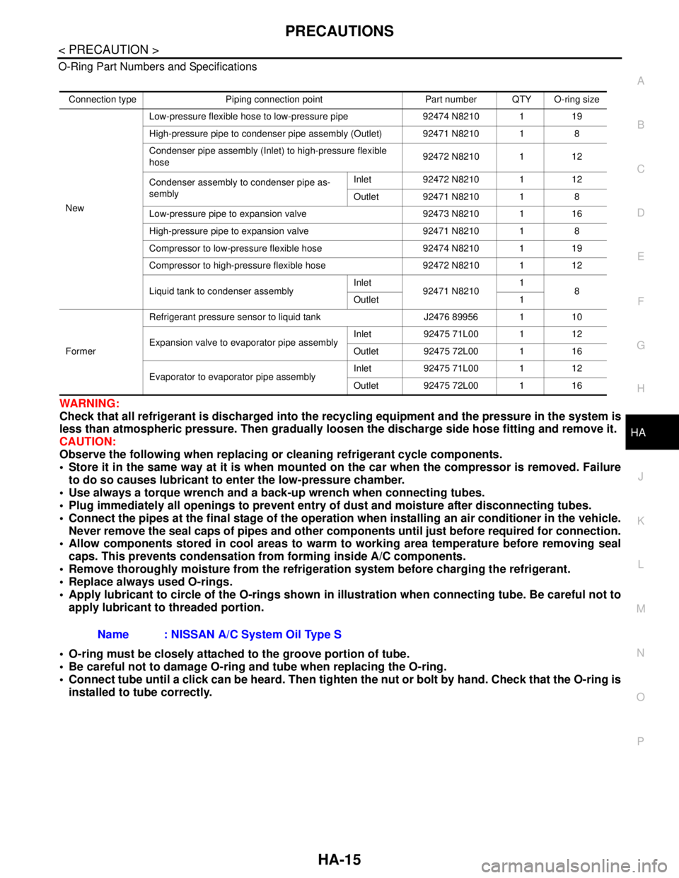
P O-Ring Part Numbers and Specifications
WARNING:
Check that all refrigerant is discharged into the recycling equipment and the pressure in the system is
less than atmospheric pressure. Then gradually loosen the discharge side hose fitting and remove it.
CAUTION:
Observe the following when replacing or cleaning refrigerant cycle components.
Store it in the same way at it is when mounted on the car when the compressor is removed. Failure
to do so causes lubricant to enter the low-pressure chamber.
Use always a torque wrench and a back-up wrench when connecting tubes.
Plug immediately all openings to prevent entry of dust and moisture after disconnecting tubes.
Connect the pipes at the final stage of the operation when installing an air conditioner in the vehicle.
Never remove the seal caps of pipes and other components until just before required for connection.
Allow components stored in cool areas to warm to working area temperature before removing seal
caps. This prevents condensation from forming inside A/C components.
Remove thoroughly moisture from the refrigeration system before charging the refrigerant.
Replace always used O-rings.
Apply lubricant to circle of the O-rings shown in illustration when connecting tube. Be careful not to
apply lubricant to threaded portion.
O-ring must be closely attached to the groove portion of tube.
Be careful not to damage O-ring and tube when replacing the O-ring.
Connect tube until a click can be heard. Then tighten the nut or bolt by hand. Check that the O-ring is
installed to tube correctly.
Connection type Piping connection point Part number QTY O-ring size
NewLow-pressure flexible hose to low-pressure pipe 92474 N8210 1 19
High-pressure pipe to condenser pipe assembly (Outlet) 92471 N8210 1 8
Condenser pipe assembly (Inlet) to high-pressure flexible
hose92472 N8210 1 12
Condenser assembly to condenser pipe as-
semblyInlet 92472 N8210 1 12
Outlet 92471 N8210 1 8
Low-pressure pipe to expansion valve 92473 N8210 1 16
High-pressure pipe to expansion valve 92471 N8210 1 8
Compressor to low-pressure flexible hose 92474 N8210 1 19
Compressor to high-pressure flexible hose 92472 N8210 1 12
Liquid tank to condenser assemblyInlet
92471 N82101
8
Outlet 1
FormerRefrigerant pressure sensor to liquid tank J2476 89956 1 10
Expansion valve to evaporator pipe assemblyInlet 92475 71L00 1 12
Outlet 92475 72L00 1 16
Evaporator to evaporator pipe assemblyInlet 92475 71L00 1 12
Outlet 92475 72L00 1 16
Name : NISSAN A/C System Oil Type S
Page 2597 of 5121

HA-28
< ON-VEHICLE MAINTENANCE >
LUBRICANT
LUBRICANT
Maintenance of Lubricant QuantityINFOID:0000000003795916
The lubricant in the compressor circulates through the system the refrigerant. Add lubricant to compressor
when replacing any component or after a large refrigerant leakage occurred. It is important to maintain the
specified amount.
If lubricant quantity is not maintained properly, the following malfunctions may result:
Lack of lubricant: May lead to a seized compressor.
Excessive lubricant: Inadequate cooling (thermal exchange interference)
LUBRICANT
LUBRICANT RETURN OPERATION
Adjust the lubricant quantity according to the test group shown below.
1.CHECK LUBRICANT RETURN OPERATION
Can lubricant return operation be performed?
A/C system works normally.
There is no evidence of a large amount of lubricant leakage.
CAUTION:
Never perform the lubricant return operation if excessive lubricant leakage is detected.
Is it successful?
YES >> GO TO 2.
NO >> GO TO 3.
2.PERFORM LUBRICANT RETURN OPERATION
1. Start the engine, and set to the following conditions:
- Engine speed: Idling to 1,200 rpm
- A/C switch: ON
- Blower speed: Max. position
- Set temperature: FULL HOT
- Intake position: Recirculation (REC)
2. Perform lubricant return operation for approximately 10 minutes.
3. Stop the engine.
>> GO TO 3.
3.CHECK REPLACEMENT PART
Should the compressor be replaced?
YES >> Refer to HA-29, "Lubricant Adjusting Procedure for Compressor Replacement".
NO >> Refer to HA-28, "
Lubricant Adjusting Procedure for Components Replacement Except Compres-
sor".
Lubricant Adjusting Procedure for Components Replacement Except Compressor
INFOID:0000000003795917
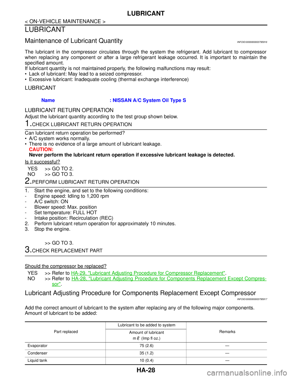
Add the correct amount of lubricant to the system after replacing any of the following major components.
Amount of lubricant to be added:Name : NISSAN A/C System Oil Type S
Part replacedLubricant to be added to system
Remarks
Amount of lubricant
m (Imp fl oz.)
Evaporator 75 (2.6) —
Condenser 35 (1.2) —
Liquid tank 10 (0.4) —
Page 2603 of 5121

HA-34
< ON-VEHICLE MAINTENANCE >
ELECTRICAL LEAK DETECTOR
2. Connect a suitable A/C manifold gauge set (SST) to the A/C service valves.
3. Check if the A/C refrigerant pressure is at least 345 kPa (3.45 bar, 3.52 kg/cm
2, 50 psi) above 16°C
(61°F). Recover/evacuate and recharge the system with the specified amount of refrigerant if less than
specification.
NOTE:
Leakages may not be detected since the system may not reach 345 kPa (3.45 bar, 3.52 kg/cm
2, 50 psi) at
temperatures below 16°C (61°F).
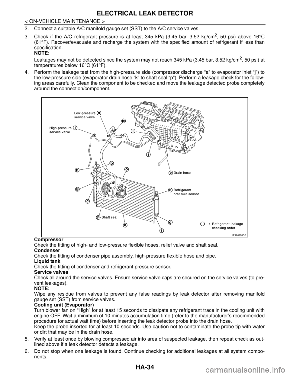
4. Perform the leakage test from the high-pressure side (compressor discharge “a” to evaporator inlet “j”) to
the low-pressure side (evaporator drain hose “k” to shaft seal “p”). Perform a leakage check for the follow-
ing areas carefully. Clean the component to be checked and move the leakage detected probe completely
around the connection/component.
Compressor
Check the fitting of high- and low-pressure flexible hoses, relief valve and shaft seal.
Condenser
Check the fitting of condenser pipe assembly, high-pressure flexible hose and pipe.
Liquid tank
Check the fitting of condenser and refrigerant pressure sensor.
Service valves
Check all around the service valves. Ensure service valve caps are secured on the service valves (to pre-
vent leakages).
NOTE:
Wipe any residue from valves to prevent any false readings by leak detector after removing manifold
gauge set (SST) from service valves.
Cooling unit (Evaporator)
Turn blower fan on “High” for at least 15 seconds to dissipate any refrigerant trace in the cooling unit with
engine OFF. Wait a minimum of 10 minutes accumulation time (refer to the manufacturer’s recommended
procedure for actual wait time) before inserting the leak detector probe into the drain hose.
Keep the probe inserted for at least 10 seconds. Use caution not to contaminate the probe tip with water
or dirt that may be in the drain hose.
5. Verify at least once by blowing compressed air into area of suspected leakage, then repeat check as out-
lined above if a leak detector detects a leakage.
6. Do not stop when one leakage is found. Continue checking for additional leakages at all system compo-
nents.
JPIIA0988GB
Page 2607 of 5121
HA-38
< ON-VEHICLE REPAIR >
LOW-PRESSURE FLEXIBLE HOSE
LOW-PRESSURE FLEXIBLE HOSE
Exploded ViewINFOID:0000000003858210
Refer to HA-14, "Refrigerant Connection".
Removal and InstallationINFOID:0000000003858211
REMOVAL
1. Use refrigerant collecting equipment (for HFC-134a) to discharge the refrigerant.
2. Remove air duct. Refer to EM-26, "
Exploded View".
3. Disengage the tab, and then move radiator hose (1) to a position
where it does not inhibit (as shown in the figure).
1. High-pressure pipe 2. O-ring 3. Condenser
4. High-pressure flexible hose 5. Compressor 6. Low-pressure flexible hose
7. Low-pressure pipe 8. Heater & cooling unit assembly 9. Blower unit
10. Evaporator pipe assembly 11. Expansion valve 12. Evaporator
Refer to GI-4, "
Components" for symbols in the figure.
JPIIA0952GB
: Tab
JPIIA0954ZZ
Page 2609 of 5121
HA-40
< ON-VEHICLE REPAIR >
HIGH-PRESSURE FLEXIBLE HOSE
HIGH-PRESSURE FLEXIBLE HOSE
Exploded ViewINFOID:0000000003839908
Refer to HA-14, "Refrigerant Connection".
Removal and InstallationINFOID:0000000003839909
REMOVAL
1. Use refrigerant collecting equipment (for HFC-134a) to discharge the refrigerant.
2. Remove air duct. Refer to EM-26, "
Exploded View".
3. Disengage the tab, and then move radiator hose (1) to a position
where it does not inhibit (as shown in the figure).
1. High-pressure pipe 2. O-ring 3. Condenser
4. High-pressure flexible hose 5. Compressor 6. Low-pressure flexible hose
7. Low-pressure pipe 8. Heater & cooling unit assembly 9. Blower unit
10. Evaporator pipe assembly 11. Expansion valve 12. Evaporator
Refer to GI-4, "
Components" for symbols in the figure.
JPIIA0952GB
: Tab
JPIIA0954ZZ
Page 2610 of 5121
HIGH-PRESSURE FLEXIBLE HOSE
HA-41
< ON-VEHICLE REPAIR >
C
D
E
F
G
H
J
K
L
MA
B
HA
N
O
P
4. Remove mounting bolt (A), and then disconnect high-pressure
flexible hose (1) from compressor.
CAUTION:
Cap or wrap the joint of the A/C piping and compressor with
suitable material such as vinyl tape to avoid the entry of air.
5. Remove mounting bolt (A), and then remove high-pressure flex-
ible hose (1) from condenser pipe assembly.
CAUTION:
Cap or wrap the joint of the A/C piping with suitable mate-
rial such as vinyl tape to avoid the entry of air.
INSTALLATION
Installation is basically the reverse order of removal.
CAUTION:
Replace O-rings with new ones. Then apply compressor oil to them when installing.
Check for leakages when recharging refrigerant.
JPIIA0962ZZ
JPIIA0963ZZ
Page 2611 of 5121
HA-42
< ON-VEHICLE REPAIR >
LOW-PRESSURE PIPE
LOW-PRESSURE PIPE
Exploded ViewINFOID:0000000003839910
Refer to HA-14, "Refrigerant Connection".
Removal and InstallationINFOID:0000000003839911
REMOVAL
1. Use refrigerant collecting equipment (for HFC-134a) to discharge the refrigerant.
2. Disengage the tab, and then move power steering reservoir tank
(1) to a position where it does not inhibit work.
3. Move upper torque rod to a position where it dose not inhibit work. Refer to EM-67, "
Exploded View".
1. High-pressure pipe 2. O-ring 3. Condenser
4. High-pressure flexible hose 5. Compressor 6. Low-pressure flexible hose
7. Low-pressure pipe 8. Heater & cooling unit assembly 9. Blower unit
10. Evaporator pipe assembly 11. Expansion valve 12. Evaporator
Refer to GI-4, "
Components" for symbols in the figure.
JPIIA0952GB
: Tab
JPIIA0965ZZ
Page 2613 of 5121
HA-44
< ON-VEHICLE REPAIR >
HIGH-PRESSURE PIPE
HIGH-PRESSURE PIPE
Exploded ViewINFOID:0000000003839912
Refer to HA-14, "Refrigerant Connection".
Removal and InstallationINFOID:0000000003839913
REMOVAL
1. Remove low-pressure pipe. Refer to HA-42, "Exploded View".
2. Disconnect high-pressure pipe (1) from expansion valve.
CAUTION:
Cap or wrap the joint of the A/C piping and expansion valve
with suitable material such as vinyl tape to avoid the entry
of air.
1. High-pressure pipe 2. O-ring 3. Condenser
4. High-pressure flexible hose 5. Compressor 6. Low-pressure flexible hose
7. Low-pressure pipe 8. Heater & cooling unit assembly 9. Blower unit
10. Evaporator pipe assembly 11. Expansion valve 12. Evaporator
Refer to GI-4, "
Components" for symbols in the figure.
JPIIA0952GB
JPIIA0972ZZ