2008 NISSAN TEANA Condenser
[x] Cancel search: CondenserPage 1806 of 5121
![NISSAN TEANA 2008 Service Manual IGNITION SIGNAL
EC-345
< COMPONENT DIAGNOSIS >[VQ25DE, VQ35DE]
C
D
E
F
G
H
I
J
K
L
MA
EC
N
P O
YES >> INSPECTION END
NO >> Replace malfunctioning ignition coil with power transistor.
Component Inspect NISSAN TEANA 2008 Service Manual IGNITION SIGNAL
EC-345
< COMPONENT DIAGNOSIS >[VQ25DE, VQ35DE]
C
D
E
F
G
H
I
J
K
L
MA
EC
N
P O
YES >> INSPECTION END
NO >> Replace malfunctioning ignition coil with power transistor.
Component Inspect](/manual-img/5/57391/w960_57391-1805.png)
IGNITION SIGNAL
EC-345
< COMPONENT DIAGNOSIS >[VQ25DE, VQ35DE]
C
D
E
F
G
H
I
J
K
L
MA
EC
N
P O
YES >> INSPECTION END
NO >> Replace malfunctioning ignition coil with power transistor.
Component Inspection (Condenser)INFOID:0000000003856852
1.CHECK CONDENSER
1. Turn ignition switch OFF.
2. Disconnect condenser harness connector.
3. Check resistance between condenser terminals as per the following.
Is the inspection result normal?
YES >> INSPECTION END
NO >> Replace condenser.
Terminals Resistance
1 and 2 Above 1 MΩ [at 25C° (77C°)]
Page 1809 of 5121
![NISSAN TEANA 2008 Service Manual EC-348
< COMPONENT DIAGNOSIS >[VQ25DE, VQ35DE]
REFRIGERANT PRESSURE SENSOR
REFRIGERANT PRESSURE SENSOR
DescriptionINFOID:0000000003856862
The refrigerant pressure sensor is installed at the condenser NISSAN TEANA 2008 Service Manual EC-348
< COMPONENT DIAGNOSIS >[VQ25DE, VQ35DE]
REFRIGERANT PRESSURE SENSOR
REFRIGERANT PRESSURE SENSOR
DescriptionINFOID:0000000003856862
The refrigerant pressure sensor is installed at the condenser](/manual-img/5/57391/w960_57391-1808.png)
EC-348
< COMPONENT DIAGNOSIS >[VQ25DE, VQ35DE]
REFRIGERANT PRESSURE SENSOR
REFRIGERANT PRESSURE SENSOR
DescriptionINFOID:0000000003856862
The refrigerant pressure sensor is installed at the condenser of the air conditioner system. The sensor uses an
electrostatic volume pressure transducer to convert refrigerant pressure to voltage. The voltage signal is sent
to ECM, and ECM controls cooling fan system.
Component Function CheckINFOID:0000000003856863
1.CHECK REFRIGERANT PRESSURE SENSOR FUNCTION
1. Start engine and warm it up to normal operating temperature.
2. Turn A/C switch and blower fan switch ON.
3. Check the voltage between ECM harness connector terminals under the following conditions.
Is the inspection result normal?
YES >> INSPECTION END
NO >> Go to EC-348, "
Diagnosis Procedure".
Diagnosis ProcedureINFOID:0000000003856864
1.CHECK GROUND CONNECTION
1. Turn A/C switch and blower fan switch OFF.
2. Stop engine.
3. Turn ignition switch OFF.
4. Check ground connection E38. Refer to Ground Inspection in GI-37, "
Circuit Inspection".
Is the inspection result normal?
YES >> GO TO 2.
NO >> Repair or replace ground connection.
2.CHECK REFRIGERANT PRESSURE SENSOR POWER SUPPLY CIRCUIT
1. Disconnect refrigerant pressure sensor harness connector.
2. Turn ignition switch ON.
3. Check the voltage between refrigerant pressure sensor harness connector and ground.
Is the inspection result normal?
YES >> GO TO 4.
PBIB2657E
ECM
Voltage (V)
Connector+–
Te r m i n a l Te r m i n a l
F839
(Refrigerant pressure sensor signal)40
(Sensor ground)1.0 - 4.0
Refrigerant pressure sensor
Ground Voltage (V)
Connector Terminal
E300 1 Ground Approx. 5
Page 1868 of 5121
![NISSAN TEANA 2008 Service Manual PRECAUTIONS
EC-407
< PRECAUTION >[VQ25DE, VQ35DE]
C
D
E
F
G
H
I
J
K
L
MA
EC
N
P O
When connecting or disconnecting pin connectors into or
from ECM, never damage pin terminals (bends or break).
Check NISSAN TEANA 2008 Service Manual PRECAUTIONS
EC-407
< PRECAUTION >[VQ25DE, VQ35DE]
C
D
E
F
G
H
I
J
K
L
MA
EC
N
P O
When connecting or disconnecting pin connectors into or
from ECM, never damage pin terminals (bends or break).
Check](/manual-img/5/57391/w960_57391-1867.png)
PRECAUTIONS
EC-407
< PRECAUTION >[VQ25DE, VQ35DE]
C
D
E
F
G
H
I
J
K
L
MA
EC
N
P O
When connecting or disconnecting pin connectors into or
from ECM, never damage pin terminals (bends or break).
Check that there are not any bends or breaks on ECM pin ter-
minal, when connecting pin connectors.
Securely connect ECM harness connectors.
A poor connection can cause an extremely high (surge) volt-
age to develop in coil and condenser, thus resulting in dam-
age to ICs.
Keep engine control system harness at least 10 cm (4 in) away
from adjacent harness, to prevent engine control system mal-
functions due to receiving external noise, degraded operation
of ICs, etc.
Keep engine control system parts and harness dry.
Before replacing ECM, perform ECM Terminals and Reference
Value inspection and check ECM functions properly. Refer to
EC-357, "
Reference Value".
Handle mass air flow sensor carefully to avoid damage.
Never clean mass air flow sensor with any type of detergent.
Never disassemble electric throttle control actuator.
Even a slight leak in the air intake system can cause serious
incidents.
Never shock or jar the camshaft position sensor (PHASE),
crankshaft position sensor (POS).
After performing each TROUBLE DIAGNOSIS, perform DTC
Confirmation Procedure or Component Function Check.
The DTC should not be displayed in the DTC Confirmation
Procedure if the repair is completed. The Component Func-
tion Check should be a good result if the repair is completed.
PBIB0090E
MEF040D
SAT652J
Page 2571 of 5121

HA-2
LOW-PRESSURE PIPE .....................................42
Exploded View ........................................................42
Removal and Installation ........................................42
HIGH-PRESSURE PIPE ....................................44
Exploded View ........................................................44
Removal and Installation ........................................44
CONDENSER ....................................................46
Exploded View ........................................................46
Removal and Installation ........................................46
CONDENSER PIPE ASSEMBLY ......................48
Exploded View ........................................................48
Removal and Installation ........................................48
LIQUID TANK ....................................................50
Exploded View ........................................................50
Removal and Installation ........................................50
REFRIGERANT PRESSURE SENSOR ............51
Exploded View ........................................................51
Removal and Installation ........................................51
EVAPORATOR ..................................................52
Exploded View ........................................................52
Removal and Installation .........................................53
EVAPORATOR PIPE ASSEMBLY ....................54
Exploded View ........................................................54
Removal and Installation .........................................55
EXPANSION VALVE .........................................57
Exploded View ........................................................57
Removal and Installation .........................................58
SERVICE DATA AND SPECIFICATIONS
(SDS) ..........................................................
59
SERVICE DATA AND SPECIFICATIONS
(SDS) .................................................................
59
Compressor ............................................................59
Lubricant .................................................................59
Refrigerant ..............................................................59
Engine Idling Speed ................................................59
Belt Tension ............................................................59
Page 2574 of 5121

REFRIGERATION SYSTEM
HA-5
< FUNCTION DIAGNOSIS >
C
D
E
F
G
H
J
K
L
MA
B
HA
N
O
P
FUNCTION DIAGNOSIS
REFRIGERATION SYSTEM
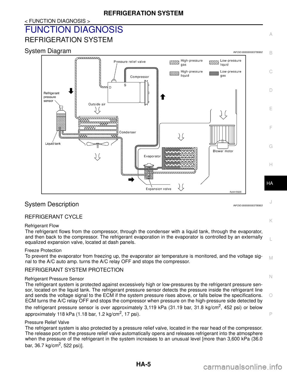
System DiagramINFOID:0000000003795802
System DescriptionINFOID:0000000003795803
REFRIGERANT CYCLE
Refrigerant Flow
The refrigerant flows from the compressor, through the condenser with a liquid tank, through the evaporator,
and then back to the compressor. The refrigerant evaporation in the evaporator is controlled by an externally
equalized expansion valve, located at dash panels.
Freeze Protection
To prevent the evaporator from freezing up, the evaporator air temperature is monitored, and the voltage sig-
nal to the A/C auto amp. turns the A/C relay OFF and stops the compressor.
REFRIGERANT SYSTEM PROTECTION
Refrigerant Pressure Sensor
The refrigerant system is protected against excessively high or low-pressures by the refrigerant pressure sen-
sor, located on the liquid tank. The refrigerant pressure sensor detects the pressure inside the refrigerant line
and sends the voltage signal to the ECM if the system pressure rises above, or falls below the specifications.
ECM turns the A/C relay OFF and stops the compressor when pressure on the high-pressure side detected by
the refrigerant pressure sensor is over approximately 3,119 kPa (31.19 bar, 31.8 kg/cm
2, 452 psi) or below
approximately 118 kPa (1.18 bar, 1.2 kg/cm
2, 17 psi).
Pressure Relief Valve
The refrigerant system is also protected by a pressure relief valve, located in the rear head of the compressor.
The release port on the pressure relief valve automatically opens and releases refrigerant into the atmosphere
when the pressure of the refrigerant in the system increases to an unusual level [more than 3,600 kPa (36.0
bar, 36.7 kg/cm
2, 522 psi)].
RJIA1552E
Page 2575 of 5121

HA-6
< FUNCTION DIAGNOSIS >
REFRIGERATION SYSTEM
Component Parts Location
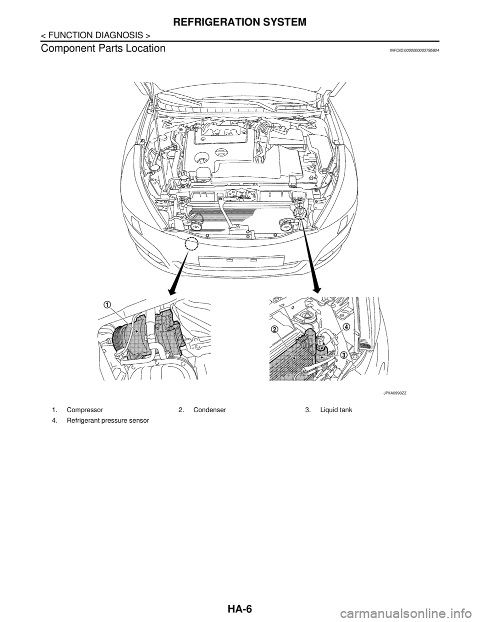
INFOID:0000000003795804
1. Compressor 2. Condenser 3. Liquid tank
4. Refrigerant pressure sensor
JPIIA0990ZZ
Page 2576 of 5121

REFRIGERATION SYSTEM
HA-7
< FUNCTION DIAGNOSIS >
C
D
E
F
G
H
J
K
L
MA
B
HA
N
O
P
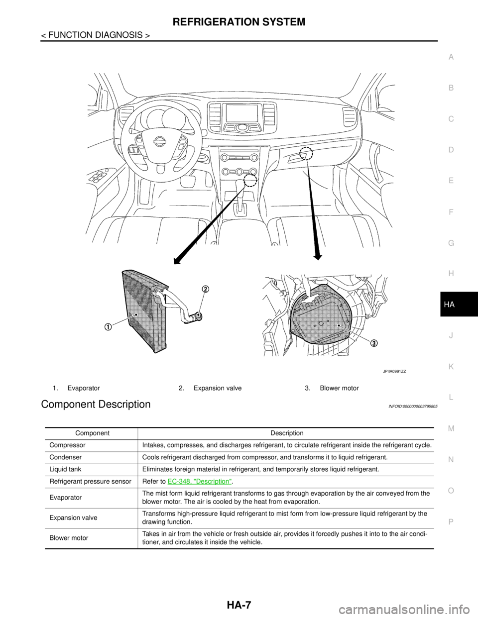
Component DescriptionINFOID:0000000003795805
1. Evaporator 2. Expansion valve 3. Blower motor
JPIIA0991ZZ
Component Description
Compressor Intakes, compresses, and discharges refrigerant, to circulate refrigerant inside the refrigerant cycle.
Condenser Cools refrigerant discharged from compressor, and transforms it to liquid refrigerant.
Liquid tank Eliminates foreign material in refrigerant, and temporarily stores liquid refrigerant.
Refrigerant pressure sensor Refer to EC-348, "
Description".
EvaporatorThe mist form liquid refrigerant transforms to gas through evaporation by the air conveyed from the
blower motor. The air is cooled by the heat from evaporation.
Expansion valveTransforms high-pressure liquid refrigerant to mist form from low-pressure liquid refrigerant by the
drawing function.
Blower motorTakes in air from the vehicle or fresh outside air, provides it forcedly pushes it into to the air condi-
tioner, and circulates it inside the vehicle.
Page 2577 of 5121

HA-8
< SYMPTOM DIAGNOSIS >
REFRIGERATION SYSTEM SYMPTOMS
SYMPTOM DIAGNOSIS
REFRIGERATION SYSTEM SYMPTOMS
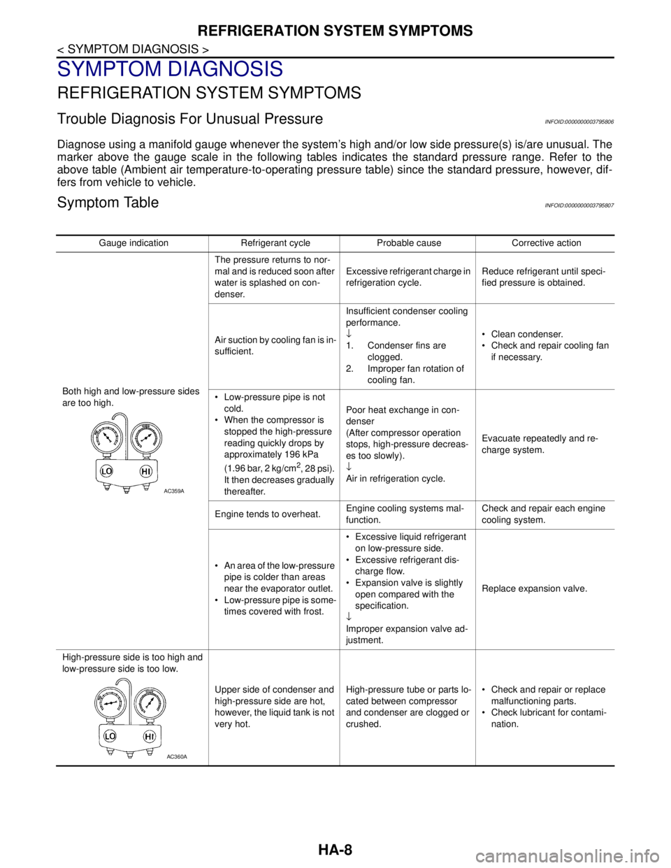
Trouble Diagnosis For Unusual PressureINFOID:0000000003795806
Diagnose using a manifold gauge whenever the system’s high and/or low side pressure(s) is/are unusual. The
marker above the gauge scale in the following tables indicates the standard pressure range. Refer to the
above table (Ambient air temperature-to-operating pressure table) since the standard pressure, however, dif-
fers from vehicle to vehicle.
Symptom TableINFOID:0000000003795807
Gauge indication Refrigerant cycle Probable cause Corrective action
Both high and low-pressure sides
are too high.The pressure returns to nor-
mal and is reduced soon after
water is splashed on con-
denser.Excessive refrigerant charge in
refrigeration cycle.Reduce refrigerant until speci-
fied pressure is obtained.
Air suction by cooling fan is in-
sufficient.Insufficient condenser cooling
performance.
↓
1. Condenser fins are
clogged.
2. Improper fan rotation of
cooling fan. Clean condenser.
Check and repair cooling fan
if necessary.
Low-pressure pipe is not
cold.
When the compressor is
stopped the high-pressure
reading quickly drops by
approximately 196 kPa
(1.96 bar, 2 kg/cm
2, 28 psi).
It then decreases gradually
thereafter.Poor heat exchange in con-
denser
(After compressor operation
stops, high-pressure decreas-
es too slowly).
↓
Air in refrigeration cycle.Evacuate repeatedly and re-
charge system.
Engine tends to overheat.Engine cooling systems mal-
function.Check and repair each engine
cooling system.
An area of the low-pressure
pipe is colder than areas
near the evaporator outlet.
Low-pressure pipe is some-
times covered with frost. Excessive liquid refrigerant
on low-pressure side.
Excessive refrigerant dis-
charge flow.
Expansion valve is slightly
open compared with the
specification.
↓
Improper expansion valve ad-
justment.Replace expansion valve.
High-pressure side is too high and
low-pressure side is too low.
Upper side of condenser and
high-pressure side are hot,
however, the liquid tank is not
very hot.High-pressure tube or parts lo-
cated between compressor
and condenser are clogged or
crushed. Check and repair or replace
malfunctioning parts.
Check lubricant for contami-
nation.
AC359A
AC360A