2008 NISSAN TEANA Condenser
[x] Cancel search: CondenserPage 179 of 5121
![NISSAN TEANA 2008 Service Manual AV
NORMAL OPERATING CONDITION
AV-35
< SYMPTOM DIAGNOSIS >[AUDIO SYSTEM]
C
D
E
F
G
H
I
J
K
L
MB A
O
P
NORMAL OPERATING CONDITION
DescriptionINFOID:0000000003765606
NOTE:
Audio operation information, NISSAN TEANA 2008 Service Manual AV
NORMAL OPERATING CONDITION
AV-35
< SYMPTOM DIAGNOSIS >[AUDIO SYSTEM]
C
D
E
F
G
H
I
J
K
L
MB A
O
P
NORMAL OPERATING CONDITION
DescriptionINFOID:0000000003765606
NOTE:
Audio operation information,](/manual-img/5/57391/w960_57391-178.png)
AV
NORMAL OPERATING CONDITION
AV-35
< SYMPTOM DIAGNOSIS >[AUDIO SYSTEM]
C
D
E
F
G
H
I
J
K
L
MB A
O
P
NORMAL OPERATING CONDITION
DescriptionINFOID:0000000003765606
NOTE:
Audio operation information, refer to Owner's Manual.
The majority of the audio concerns are the result of outside causes (bad CD, electromagnetic interference,
etc.).
NOISE
The following noise results from variations in field strength, such as fading noise and multi-path noise, or
external noise from trains and other sources. It is not a malfunction.
Fading noise: This noise occurs because of variations in the field strength in a narrow range due to moun-
tains or buildings blocking the signal.
Multi-path noise: This noise results from the waves sent directly from the broadcast station arriving at the
antenna at a different time from the waves that reflect off mountains or buildings.
The vehicle itself can be a source of noise if noise prevention parts or electrical equipment is malfunctioning.
Check if noise is caused and/or changed by engine speed, ignition switch turned to each position, and opera-
tion of each piece of electrical equipment, and then determine the cause.
NOTE:
The source of the noise can be easily found by listening to the noise while removing the fuses of electrical
components, one by one.
Types of Noise and Possible Causes
Occurrence condition Possible cause
Occurs only when engine is ON.A continuous growling noise occurs. The speed of
the noise varies with changes in the engine speed. Ignition components
The occurrence of the noise is linked with the operation of the fuel pump. Fuel pump condenser
Noise only occurs when various
electrical components are oper-
ating.A cracking or snapping sound occurs with the op-
eration of various switches. Relay malfunction, audio unit malfunction
The noise occurs when various motors are operat-
ing. Motor case ground
Motor
The noise occurs constantly, not just under certain conditions. Rear defogger coil malfunction
Open circuit in printed heater
Poor ground of antenna feeder line
A cracking or snapping sound occurs while the vehicle is being driven, especially when
it is vibrating excessively. Ground wire of body parts
Ground due to improper part installation
Wiring connections or a short circuit
Page 1127 of 5121

CO-4
< SYMPTOM DIAGNOSIS >
OVERHEATING CAUSE ANALYSIS
Except cool-
ing system
parts mal-
function— Overload on engineAbusive drivingHigh engine rpm under no
load
Driving in low gear for ex-
tended time
Driving at extremely high
speed
Powertrain system malfunc-
tion
— Installed improper size
wheels and tires
Dragging brakes
Improper ignition timing
Blocked or restricted air
flowBlocked bumper —
— Blocked radiator grilleInstalled car brassiere
Mud contamination or paper
clogging
Blocked radiator —
Blocked condenser
Blocked air flow
Installed large fog lamp Symptom Check items
Page 1137 of 5121
CO-14
< ON-VEHICLE REPAIR >
RADIATOR
WARNING:
Never remove radiator cap when engine is hot. Serious burns could occur from high-pressure engine
coolant escaping from radiator. Wrap a thick cloth around the cap. Slowly turn it a quarter of a turn to
release built-up pressure. Carefully remove radiator cap by turning it all the way.
1. Remove the following parts:
Engine under cover.
Air duct (inlet): Refer to EM-26, "
Exploded View".
Horn: Refer to HRN-6, "
Exploded View".
Hood lock: Refer to DLK-220, "
Exploded View".
2. Drain engine coolant from radiator. Refer to CO-8, "
Draining".
CAUTION:
Perform this step when the engine is cold.
Never spill engine coolant on drive belt.
3. Disconnect reservoir tank hose from radiator pipe (upper).
4. Disconnect CVT fluid cooler hoses from radiator.
Install blind plug to avoid leakage of CVT fluid.
5. Disconnect Low-pressure flexible hose from lower pressure pipe, and then move it to aside. Refer to HA-
38, "Exploded View".
6. Remove radiator cap adapter and radiator hoses (upper) and radiator pipe (upper) assembly.
CAUTION:
Be careful not to allow engine coolant to contact drive belt.
7. Disconnect radiator hose (lower) from radiator.
8. Remove condenser. Refer to HA-46, "
Exploded View".
CAUTION:
Be careful not to damage condenser core.
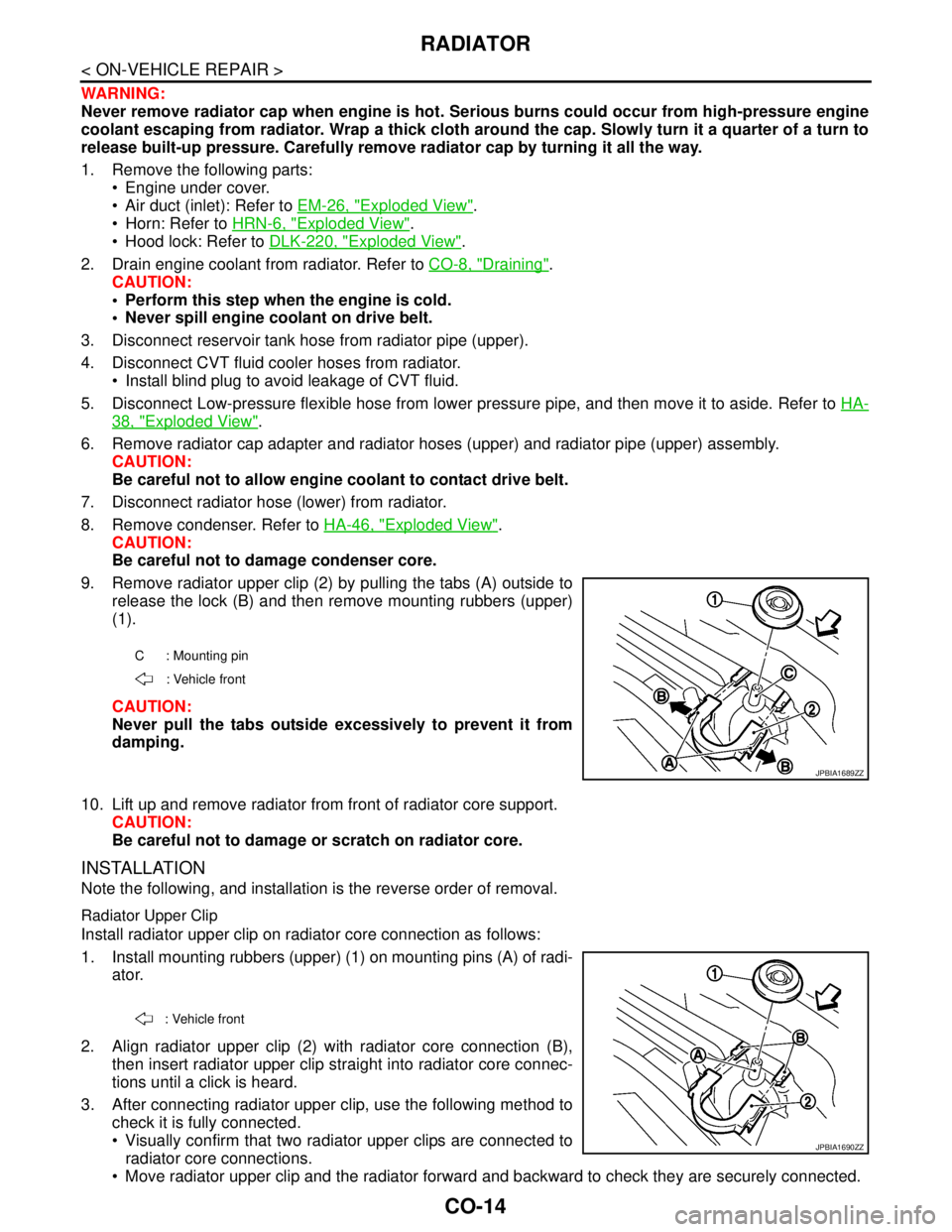
9. Remove radiator upper clip (2) by pulling the tabs (A) outside to
release the lock (B) and then remove mounting rubbers (upper)
(1).
CAUTION:
Never pull the tabs outside excessively to prevent it from
damping.
10. Lift up and remove radiator from front of radiator core support.
CAUTION:
Be careful not to damage or scratch on radiator core.
INSTALLATION
Note the following, and installation is the reverse order of removal.
Radiator Upper Clip
Install radiator upper clip on radiator core connection as follows:
1. Install mounting rubbers (upper) (1) on mounting pins (A) of radi-
ator.
2. Align radiator upper clip (2) with radiator core connection (B),
then insert radiator upper clip straight into radiator core connec-
tions until a click is heard.
3. After connecting radiator upper clip, use the following method to
check it is fully connected.
Visually confirm that two radiator upper clips are connected to
radiator core connections.
Move radiator upper clip and the radiator forward and backward to check they are securely connected.
C : Mounting pin
: Vehicle front
JPBIA1689ZZ
: Vehicle front
JPBIA1690ZZ
Page 1152 of 5121

DEF-2
Description ..............................................................25
Component Function Check ...................................25
Diagnosis Procedure ..............................................25
ECU DIAGNOSIS ........................................26
BCM (BODY CONTROL MODULE) ..................26
Reference Value .....................................................26
Wiring Diagram - DEFOGGER SYSTEM - .............49
Fail-safe ..................................................................53
DTC Inspection Priority Chart ..............................55
DTC Index ..............................................................56
SYMPTOM DIAGNOSIS .............................58
REAR WINDOW DEFOGGER AND DOOR
MIRROR DEFOGGER DO NOT OPERATE. .....
58
Diagnosis Procedure ..............................................58
REAR WINDOW DEFOGGER DOES NOT
OPERATE BUT BOTH DOOR MIRROR DE-
FOGGERS OPERATE. ......................................
59
Diagnosis Procedure ..............................................59
DOOR MIRROR DEFOGGER DOES NOT OP-
ERATE ...............................................................
60
BOTH SIDES .............................................................60
BOTH SIDES : Diagnosis Procedure .....................60
DRIVER SIDE ............................................................60
DRIVER SIDE : Diagnosis Procedure ....................60
PASSENGER SIDE ...................................................60
PASSENGER SIDE : Diagnosis Procedure ...........60
ON IS NOT DISPLAYED WHEN PRESSING
REAR WINDOW DEFOGGER SWITCH BUT
IT OPERATES ...................................................
61
WITH AV CONTROL UNIT ........................................61
WITH AV CONTROL UNIT : Diagnosis Procedure ...61
WITHOUT AV CONTROL UNIT ................................61
WITHOUT AV CONTROL UNIT : Diagnosis Pro-
cedure .....................................................................
61
REAR WINDOW DEFOGGER INDICATOR
DOES NOT ILLUMINATE ..................................
62
WITH AV CONTROL UNIT ........................................62
WITH AV CONTROL UNIT : Diagnosis Procedure ...62
WITHOUT AV CONTROL UNIT ................................62
WITHOUT AV CONTROL UNIT : Diagnosis Pro-
cedure .....................................................................
62
PRECAUTION ............................................63
PRECAUTIONS .................................................63
Precaution for Supplemental Restraint System
(SRS) "AIR BAG" and "SEAT BELT PRE-TEN-
SIONER" .................................................................
63
ON-VEHICLE REPAIR ...............................64
FILAMENT .........................................................64
Inspection and Repair .............................................64
CONDENSER ....................................................66
Exploded View ........................................................66
Removal and Installation .........................................66
Page 1155 of 5121
REAR WINDOW DEFOGGER SYSTEM
DEF-5
< FUNCTION DIAGNOSIS >
C
D
E
F
G
H
I
J
K
MA
B
DEF
N
O
P
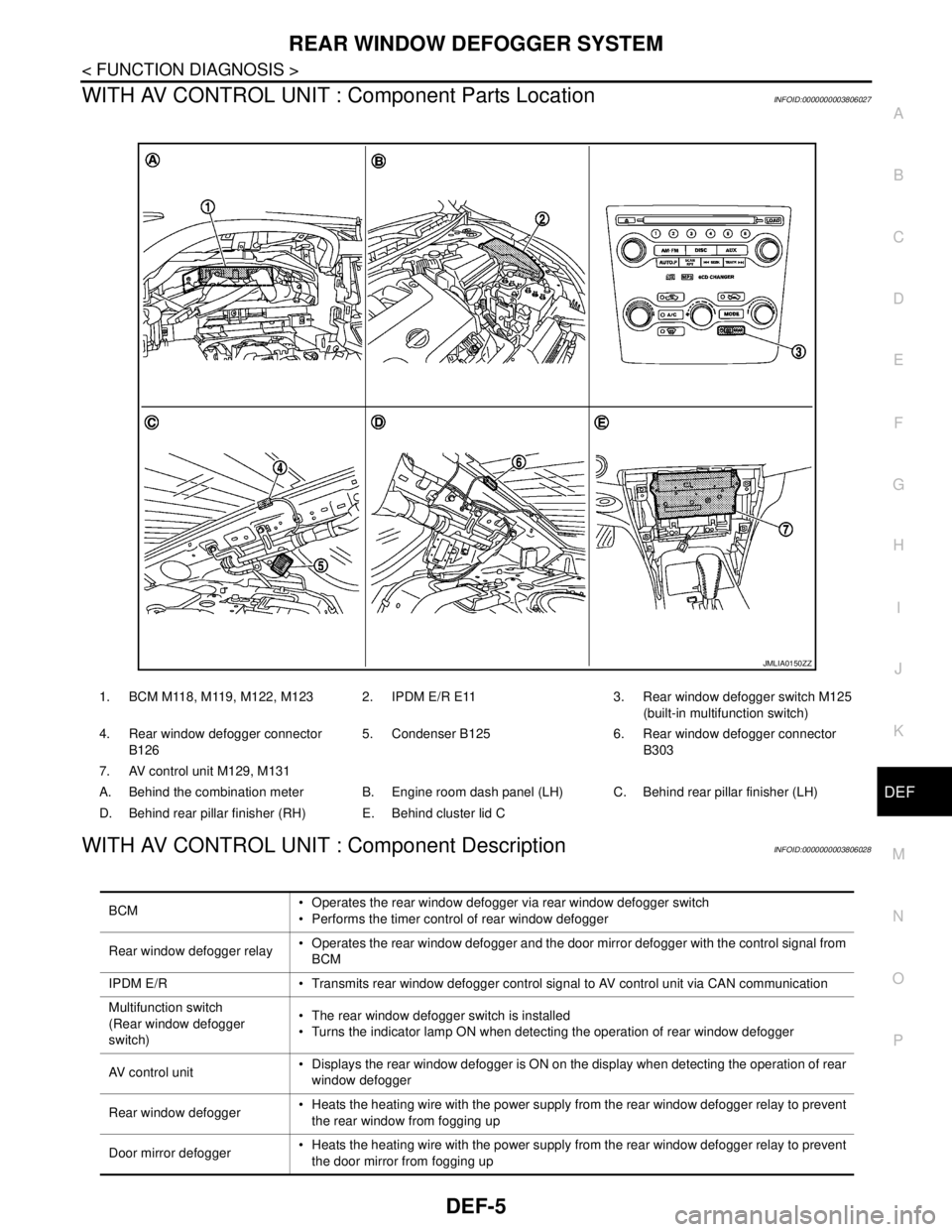
WITH AV CONTROL UNIT : Component Parts LocationINFOID:0000000003806027
WITH AV CONTROL UNIT : Component DescriptionINFOID:0000000003806028
1. BCM M118, M119, M122, M123 2. IPDM E/R E11 3. Rear window defogger switch M125
(built-in multifunction switch)
4. Rear window defogger connector
B1265. Condenser B125 6. Rear window defogger connector
B303
7. AV control unit M129, M131
A. Behind the combination meter B. Engine room dash panel (LH) C. Behind rear pillar finisher (LH)
D. Behind rear pillar finisher (RH) E. Behind cluster lid C
JMLIA0150ZZ
BCM Operates the rear window defogger via rear window defogger switch
Performs the timer control of rear window defogger
Rear window defogger relay Operates the rear window defogger and the door mirror defogger with the control signal from
BCM
IPDM E/R Transmits rear window defogger control signal to AV control unit via CAN communication
Multifunction switch
(Rear window defogger
switch) The rear window defogger switch is installed
Turns the indicator lamp ON when detecting the operation of rear window defogger
AV control unit Displays the rear window defogger is ON on the display when detecting the operation of rear
window defogger
Rear window defogger Heats the heating wire with the power supply from the rear window defogger relay to prevent
the rear window from fogging up
Door mirror defogger Heats the heating wire with the power supply from the rear window defogger relay to prevent
the door mirror from fogging up
Page 1157 of 5121
REAR WINDOW DEFOGGER SYSTEM
DEF-7
< FUNCTION DIAGNOSIS >
C
D
E
F
G
H
I
J
K
MA
B
DEF
N
O
P
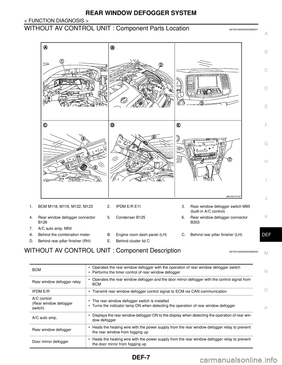
WITHOUT AV CONTROL UNIT : Component Parts LocationINFOID:0000000003806031
WITHOUT AV CONTROL UNIT : Component DescriptionINFOID:0000000003806032
1. BCM M118, M119, M122, M123 2. IPDM E/R E11 3. Rear window defogger switch M95
(built-in A/C control)
4. Rear window defogger connector
B1265. Condenser B125 6. Rear window defogger connector
B303
7. A/C auto amp. M50
A. Behind the combination meter B. Engine room dash panel (LH) C. Behind rear pillar finisher (LH)
D. Behind rear pillar finisher (RH) E. Behind cluster lid C
JMLIA0151ZZ
BCM Operates the rear window defogger with the operation of rear window defogger switch
Performs the timer control of rear window defogger
Rear window defogger relay Operates the rear window defogger and the door mirror defogger with the control signal from
BCM
IPDM E/R Transmit rear window defogger control signal to ECM via CAN communication
A/C control
(Rear window defogger
switch) The rear window defogger switch is installed
Turns the indicator lamp ON when detecting the operation of rear window defogger
A/C auto amp. Displays the rear window defogger ON to the display when detecting the operation of rear win-
dow defogger
Rear window defogger Heats the heating wire with the power supply from the rear window defogger relay to prevent
the rear window from fogging up
Door mirror defogger Heats the heating wire with the power supply from the rear window defogger relay to prevent
the door mirror from fogging up
Page 1166 of 5121
DEF-16
< COMPONENT DIAGNOSIS >
REAR WINDOW DEFOGGER
REAR WINDOW DEFOGGER
DescriptionINFOID:0000000003857615
Heats the heating wire with the power supply from the rear window defogger relay to prevent the rear window
from fogging up.
Component Function CheckINFOID:0000000003857616
1.CHECK REAR WINDOW DEFOGGER
1. Perform Active Test (“REAR DEFOGGER”) with CONSULT-III.
2. Touch “ON”.
3. Check that the rear window heating wire is getting warmer.
Is the inspection result normal?
YES >> Rear window defogger is OK.
NO >> Refer to DEF-16, "
Diagnosis Procedure"
Diagnosis ProcedureINFOID:0000000003857617
1.CHECK FUSE
1. Turn ignition switch OFF.
2. Check 20A fuse [No.15, located in fuse block (J/B)].
Is the inspection result normal?
YES >> GO TO 2.
NO >> Replace the blown fuse after repairing the affected circuit if a fuse is blown.
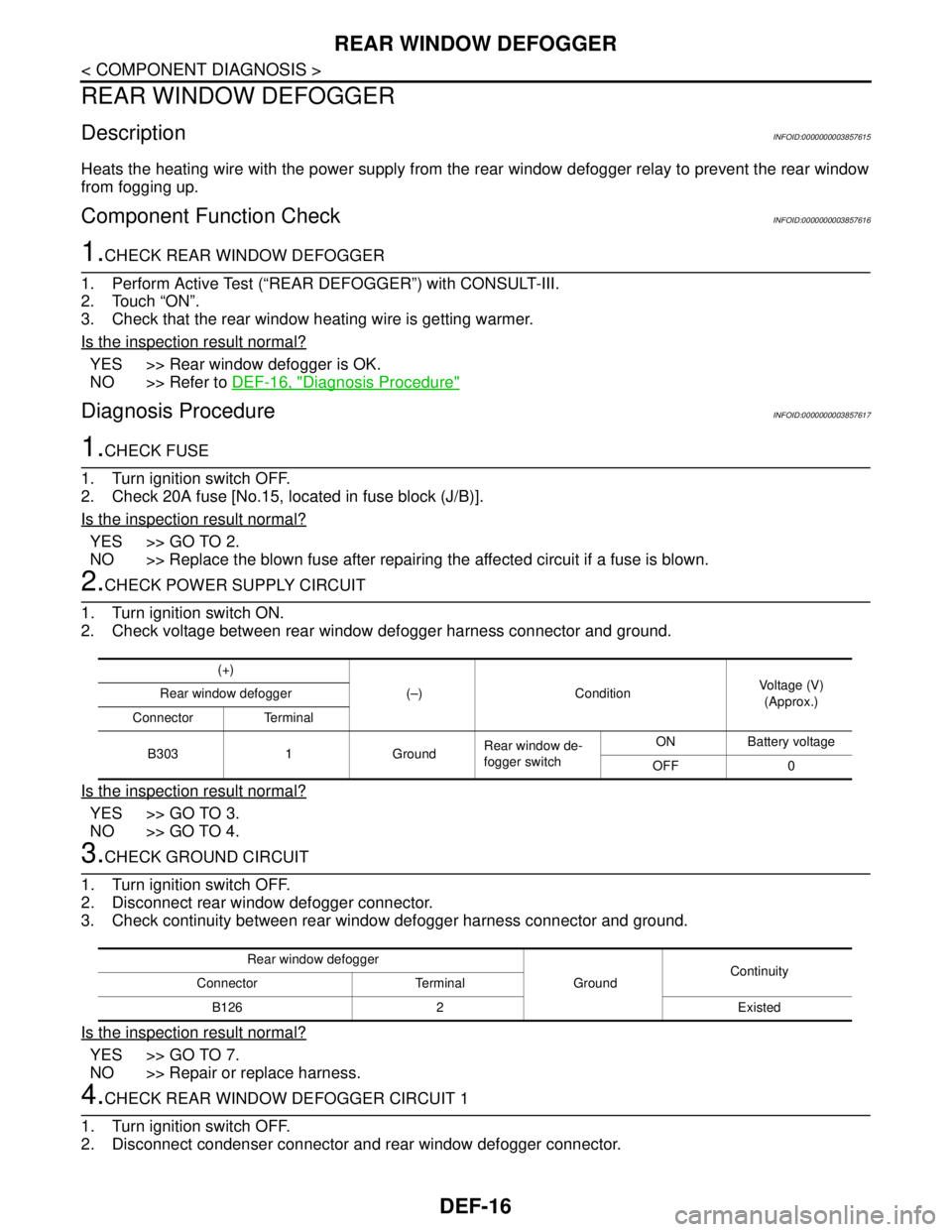
2.CHECK POWER SUPPLY CIRCUIT
1. Turn ignition switch ON.
2. Check voltage between rear window defogger harness connector and ground.
Is the inspection result normal?
YES >> GO TO 3.
NO >> GO TO 4.
3.CHECK GROUND CIRCUIT
1. Turn ignition switch OFF.
2. Disconnect rear window defogger connector.
3. Check continuity between rear window defogger harness connector and ground.
Is the inspection result normal?
YES >> GO TO 7.
NO >> Repair or replace harness.
4.CHECK REAR WINDOW DEFOGGER CIRCUIT 1
1. Turn ignition switch OFF.
2. Disconnect condenser connector and rear window defogger connector.
(+)
(–) Condition Voltage (V)
(Approx.) Rear window defogger
Connector Terminal
B303 1 GroundRear window de-
fogger switchON Battery voltage
OFF 0
Rear window defogger
GroundContinuity
Connector Terminal
B126 2 Existed
Page 1167 of 5121
REAR WINDOW DEFOGGER
DEF-17
< COMPONENT DIAGNOSIS >
C
D
E
F
G
H
I
J
K
MA
B
DEF
N
O
P
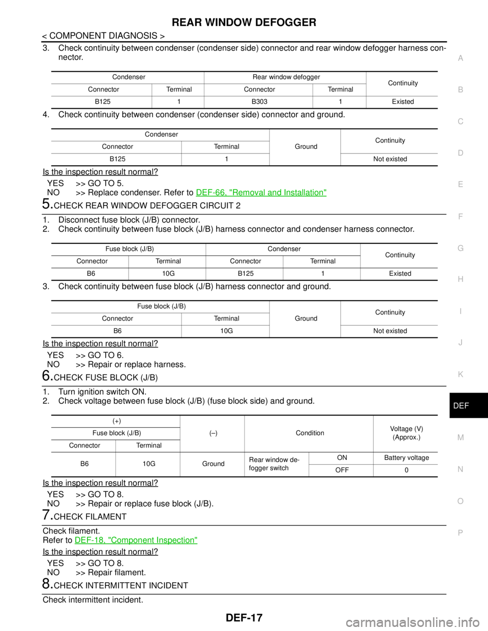
3. Check continuity between condenser (condenser side) connector and rear window defogger harness con-
nector.
4. Check continuity between condenser (condenser side) connector and ground.
Is the inspection result normal?
YES >> GO TO 5.
NO >> Replace condenser. Refer to DEF-66, "
Removal and Installation"
5.CHECK REAR WINDOW DEFOGGER CIRCUIT 2
1. Disconnect fuse block (J/B) connector.
2. Check continuity between fuse block (J/B) harness connector and condenser harness connector.
3. Check continuity between fuse block (J/B) harness connector and ground.
Is the inspection result normal?
YES >> GO TO 6.
NO >> Repair or replace harness.
6.CHECK FUSE BLOCK (J/B)
1. Turn ignition switch ON.
2. Check voltage between fuse block (J/B) (fuse block side) and ground.
Is the inspection result normal?
YES >> GO TO 8.
NO >> Repair or replace fuse block (J/B).
7.CHECK FILAMENT
Check filament.
Refer to DEF-18, "
Component Inspection"
Is the inspection result normal?
YES >> GO TO 8.
NO >> Repair filament.
8.CHECK INTERMITTENT INCIDENT
Check intermittent incident.
Condenser Rear window defogger
Continuity
Connector Terminal Connector Terminal
B125 1 B303 1 Existed
Condenser
GroundContinuity
Connector Terminal
B125 1 Not existed
Fuse block (J/B) Condenser
Continuity
Connector Terminal Connector Terminal
B6 10G B125 1 Existed
Fuse block (J/B)
GroundContinuity
Connector Terminal
B6 10G Not existed
(+)
(–) ConditionVoltage (V)
(Approx.) Fuse block (J/B)
Connector Terminal
B6 10G GroundRear window de-
fogger switchON Battery voltage
OFF 0