2008 NISSAN TEANA Ccu
[x] Cancel search: CcuPage 4303 of 5121
SRC-60
< COMPONENT DIAGNOSIS >
B1086 PRE-TEN FRONT LH
B1086 PRE-TEN FRONT LH
DescriptionINFOID:0000000003813999
For front LH seat belt pre-tensioner, crash is judged by main “G” sensor output signal and safing algorithm in
front direction.
OPERATION
In the case of a frontal collision that exceeds specified impact level, the air bag diagnosis sensor unit detects
the deceleration caused by collision. It restrains the passenger with seat belt easing the stress on passengers
chest with load limiter.
STRUCTURE
The restraint system for front seat occupant consists of the pre-tensioner mechanism and load limiter mecha-
nism.
INSTALLATION
Front LH seat belt pre-tensioner is installed on the underside of center pillar with fixed nuts.
DTC LogicINFOID:0000000003814000
DTC CONFIRMATION PROCEDURE
1.CHECK SELF-DIAG RESULT
With CONSULT-III
1. Turn ignition switch ON.
2. Perform “AIR BAG” Self Diagnostic Result.
Without CONSULT-III
1. Turn ignition switch ON.
2. Check the air bag warning lamp status. Refer to SRC-10, "
Air Bag Warning Lamp Diagnosis".
NOTE:
SRS does not enter Diagnosis mode if no malfunction is detected in User mode.
Is malfunctioning part detected?
YES >> Refer to SRC-60, "Diagnosis Procedure".
NO >> INSPECTION END
Diagnosis ProcedureINFOID:0000000003814001
WARNING:
Before servicing, turn ignition switch OFF, disconnect battery negative terminal and wait at least 3
minutes. (To discharge backup capacitor.)
Never use unspecified tester or other measuring device.
1.CHECK HARNESS CONNECTOR
Check the harness connector.
Is the inspection result normal?
YES >> GO TO 2.
NO >> Replace harness connector.
2.CHECK WIRING HARNESS
Check the wiring harness externals.
Is the inspection result normal?
DTC No. Trouble diagnosis name DTC detecting condition Possible cause
B1086 PRE-TEN FRONT LH
[OPEN]Front LH seat belt pre-tensioner circuit
is open Disconnection of wiring harness and
open
Malfunction in front LH seat belt pre-
tensioner
Malfunction in air bag diagnosis sen-
sor unit
Page 4305 of 5121
SRC-62
< COMPONENT DIAGNOSIS >
B1087 PRE-TEN FRONT LH
B1087 PRE-TEN FRONT LH
DescriptionINFOID:0000000003814002
For front LH seat belt pre-tensioner, crash is judged by main “G” sensor output signal and safing algorithm in
front direction.
OPERATION
In the case of a frontal collision that exceeds specified impact level, the air bag diagnosis sensor unit detects
the deceleration caused by collision. It restrains the passenger with seat belt easing the stress on passengers
chest with load limiter.
STRUCTURE
The restraint system for front seat occupant consists of the pre-tensioner mechanism and load limiter mecha-
nism.
INSTALLATION
Front LH seat belt pre-tensioner is installed on the underside of center pillar with fixed nuts.
DTC LogicINFOID:0000000003814003
DTC CONFIRMATION PROCEDURE
1.CHECK SELF-DIAG RESULT
With CONSULT-III
1. Turn ignition switch ON.
2. Perform “AIR BAG” Self Diagnostic Result.
Without CONSULT-III
1. Turn ignition switch ON.
2. Check the air bag warning lamp status. Refer to SRC-10, "
Air Bag Warning Lamp Diagnosis".
NOTE:
SRS does not enter Diagnosis mode if no malfunction is detected in User mode.
Is malfunctioning part detected?
YES >> Refer to SRC-62, "Diagnosis Procedure".
NO >> INSPECTION END
Diagnosis ProcedureINFOID:0000000003814004
WARNING:
Before servicing, turn ignition switch OFF, disconnect battery negative terminal and wait at least 3
minutes. (To discharge backup capacitor.)
Never use unspecified tester or other measuring device.
1.CHECK HARNESS CONNECTOR
Check the harness connector.
Is the inspection result normal?
YES >> GO TO 2.
NO >> Replace harness connector.
2.CHECK WIRING HARNESS
Check the wiring harness externals.
Is the inspection result normal?
DTC No. Trouble diagnosis name DTC detecting condition Possible cause
B1087 PRE-TEN FRONT LH
[VB-SHORT]Front LH seat belt pre-tensioner circuit
is shorted to some power supply circuit Disconnection of wiring harness and
short
Malfunction in front LH seat belt pre-
tensioner
Malfunction in air bag diagnosis sen-
sor unit
Page 4307 of 5121
SRC-64
< COMPONENT DIAGNOSIS >
B1088 PRE-TEN FRONT LH
B1088 PRE-TEN FRONT LH
DescriptionINFOID:0000000003814005
For front LH seat belt pre-tensioner, crash is judged by main “G” sensor output signal and safing algorithm in
front direction.
OPERATION
In the case of a frontal collision that exceeds specified impact level, the air bag diagnosis sensor unit detects
the deceleration caused by collision. It restrains the passenger with seat belt easing the stress on passengers
chest with load limiter.
STRUCTURE
The restraint system for front seat occupant consists of the pre-tensioner mechanism and load limiter mecha-
nism.
INSTALLATION
Front LH seat belt pre-tensioner is installed on the underside of center pillar with fixed nuts.
DTC LogicINFOID:0000000003814006
DTC CONFIRMATION PROCEDURE
1.CHECK SELF-DIAG RESULT
With CONSULT-III
1. Turn ignition switch ON.
2. Perform “AIR BAG” Self Diagnostic Result.
Without CONSULT-III
1. Turn ignition switch ON.
2. Check the air bag warning lamp status. Refer to SRC-10, "
Air Bag Warning Lamp Diagnosis".
NOTE:
SRS does not enter Diagnosis mode if no malfunction is detected in User mode.
Is malfunctioning part detected?
YES >> Refer to SRC-64, "Diagnosis Procedure".
NO >> INSPECTION END
Diagnosis ProcedureINFOID:0000000003814007
WARNING:
Before servicing, turn ignition switch OFF, disconnect battery negative terminal and wait at least 3
minutes. (To discharge backup capacitor.)
Never use unspecified tester or other measuring device.
1.CHECK HARNESS CONNECTOR
Check the harness connector.
Is the inspection result normal?
YES >> GO TO 2.
NO >> Replace harness connector.
2.CHECK WIRING HARNESS
Check the wiring harness externals.
Is the inspection result normal?
DTC No. Trouble diagnosis name DTC detecting condition Possible cause
B1088 PRE-TEN FRONT LH
[GND-SHORT]Front LH seat belt pre-tensioner circuit
is shorted to ground Disconnection of wiring harness and
short
Malfunction in front LH seat belt pre-
tensioner
Malfunction in air bag diagnosis sen-
sor unit
Page 4309 of 5121
SRC-66
< COMPONENT DIAGNOSIS >
B1089 PRE-TEN FRONT LH
B1089 PRE-TEN FRONT LH
DescriptionINFOID:0000000003814008
For front LH seat belt pre-tensioner, crash is judged by main “G” sensor output signal and safing algorithm in
front direction.
OPERATION
In the case of a frontal collision that exceeds specified impact level, the air bag diagnosis sensor unit detects
the deceleration caused by collision. It restrains the passenger with seat belt easing the stress on passengers
chest with load limiter.
STRUCTURE
The restraint system for front seat occupant consists of the pre-tensioner mechanism and load limiter mecha-
nism.
INSTALLATION
Front LH seat belt pre-tensioner is installed on the underside of center pillar with fixed nuts.
DTC LogicINFOID:0000000003814009
DTC CONFIRMATION PROCEDURE
1.CHECK SELF-DIAG RESULT
With CONSULT-III
1. Turn ignition switch ON.
2. Perform “AIR BAG” Self Diagnostic Result.
Without CONSULT-III
1. Turn ignition switch ON.
2. Check the air bag warning lamp status. Refer to SRC-10, "
Air Bag Warning Lamp Diagnosis".
NOTE:
SRS does not enter Diagnosis mode if no malfunction is detected in User mode.
Is malfunctioning part detected?
YES >> Refer to SRC-66, "Diagnosis Procedure".
NO >> INSPECTION END
Diagnosis ProcedureINFOID:0000000003814010
WARNING:
Before servicing, turn ignition switch OFF, disconnect battery negative terminal and wait at least 3
minutes. (To discharge backup capacitor.)
Never use unspecified tester or other measuring device.
1.CHECK HARNESS CONNECTOR
Check the harness connector.
Is the inspection result normal?
YES >> GO TO 2.
NO >> Replace harness connector.
2.CHECK WIRING HARNESS
Check the wiring harness externals.
Is the inspection result normal?
DTC No. Trouble diagnosis name DTC detecting condition Possible cause
B1089 PRE-TEN FRONT LH
[SHORT]Front LH seat belt pre-tensioner circuit
are shorted to each other Disconnection of wiring harness and
short
Malfunction in front LH seat belt pre-
tensioner
Malfunction in air bag diagnosis sen-
sor unit
Page 4397 of 5121
POWER STEERING FLUID
ST-7
< ON-VEHICLE MAINTENANCE >
C
D
E
F
H
I
J
K
L
MA
B
ST
N
O
P
ON-VEHICLE MAINTENANCE
POWER STEERING FLUID
InspectionINFOID:0000000003826225
FLUID LEVEL
1. Check fluid level with engine stopped.
2. Ensure that fluid level is between MIN and MAX.
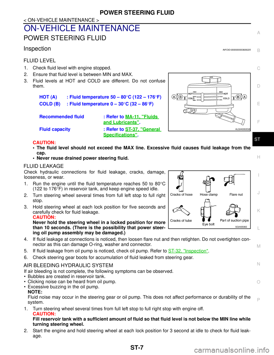
3. Fluid levels at HOT and COLD are different. Do not confuse
them.
CAUTION:
The fluid level should not exceed the MAX line. Excessive fluid causes fluid leakage from the
cap.
Never reuse drained power steering fluid.
FLUID LEAKAGE
Check hydraulic connections for fluid leakage, cracks, damage,
looseness, or wear.
1. Run the engine until the fluid temperature reaches 50 to 80°C
(122 to 176°F) in reservoir tank, and keep engine speed idle.
2. Turn steering wheel several times from full left stop to full right
stop.
3. Hold steering wheel at each lock position for five seconds and
carefully check for fluid leakage.
CAUTION:
Never hold the steering wheel in a locked position for more
than 10 seconds. (There is the possibility that power steer-
ing oil pump assembly may be damaged.)
4. If fluid leakage at connections is noticed, then loosen flare nut and then retighten. Do not overtighten con-
nector as this can damage O-ring, washer and connector.
5. If fluid leakage from oil pump is noticed, check oil pump. Refer to ST-32, "
Inspection".
6. Check steering gear boots for accumulation of fluid leaked from steering gear.
AIR BLEEDING HYDRAULIC SYSTEM
If air bleeding is not complete, the following symptoms can be observed.
Bubbles are created in reservoir tank.
Clicking noise can be heard from oil pump.
Excessive buzzing in the oil pump.
NOTE:
Fluid noise may occur in the steering gear or oil pump. This does not affect performance or durability of the
system.
1. Turn steering wheel several times from full left stop to full right stop with engine off.
CAUTION:
Fill reservoir tank with a sufficient amount of fluid so that fluid level is not below the MIN line while
turning steering wheel.
2. Start the engine and hold steering wheel at each lock position for 3 second at idle to check for fluid leak-
age.HOT (A) : Fluid temperature 50 – 80°C (122 – 176°F)
COLD (B) : Fluid temperature 0 – 30°C (32 – 86°F)
Recommended fluid : Refer to MA-11, "
Fluids
and Lubricants".
Fluid capacity : Refer to ST-37, "
General
Specifications".
ALGIA0002GB
SGIA0506E
Page 4423 of 5121

POWER STEERING OIL PUMP
ST-33
< ON-VEHICLE REPAIR >
C
D
E
F
H
I
J
K
L
MA
B
ST
N
O
P
7. Check fluid level, fluid leakage and air bleeding hydraulic system after the installation. Refer to ST-7,
"Inspection".
BEFORE DISASSEMBLY
Disassemble oil pump only when the following malfunctions occur.
If oil leakage is found on oil pump.
Oil pump pulley is damaged or deformed.
Performance of oil pump is low.
AFTER DISASSEMBLY
Body Assembly and Rear Cover Inspection
Check body assembly and rear cover for internal damage. Replace rear cover if it is damaged. Replace oil
pump assembly if body assembly is damaged.
Cartridge Assembly Inspection
Check cam ring, rotor and vane for damage. Replace cartridge assembly if necessary.
Side Plate Inspection
Check side plate for damage. Replace side plate if necessary.
Flow Control Valve Inspection
Check flow control valve and spring for damage. Replace if necessary.
Page 4432 of 5121
STC-4
< FUNCTION DIAGNOSIS >
EPS SYSTEM
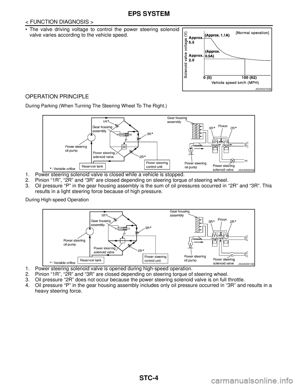
The valve driving voltage to control the power steering solenoid
valve varies according to the vehicle speed.
OPERATION PRINCIPLE
During Parking (When Turning The Steering Wheel To The Right.)
1. Power steering solenoid valve is closed while a vehicle is stopped.
2. Pinion “1R”, “2R” and “3R” are closed depending on steering torque of steering wheel.
3. Oil pressure “P” in the gear housing assembly is the sum of oil pressures occurred in “2R” and “3R”. This
results in a light steering force because of high pressure.
During High-speed Operation
1. Power steering solenoid valve is opened during high-speed operation.
2. Pinion “1R”, “2R” and “3R” are closed depending on steering torque of steering wheel.
3. Oil pressure “2R” does not occur because the power steering solenoid valve is on full throttle.
4. Oil pressure “P” in the gear housing assembly includes only oil pressure occurred in “3R” and results in a
heavy steering force.
JSGIA0374GB
JSGIA0020GB
JSGIA0021GB
Page 4451 of 5121
STR-4
< BASIC INSPECTION >
DIAGNOSIS AND REPAIR WORKFLOW
NO >> Repair as needed.
9.CHECK MAGNETIC SWITCH OPERATION SOUND
Check that a magnetic switch operation sound can be heard when the ignition switch is set at the starting posi-
tion.
Does magnetic switch operation sound occur?
YES >> GO TO 10.
NO >> Replace magnetic switch.
10.PINION AND RING GEAR ENGAGEMENT CHECK
Check condition of pinion and ring gear mesh.
Is the inspection result normal?
YES >> GO TO 12.
NO >> GO TO 11.
11 .CHECK STARTER MOTOR UNIT
Check the following.
Adjust pinion movement. Refer to the following.
- VQ25DE models: STR-16, "
VQ25DE : Inspection"
- VQ35DE models: STR-22, "VQ35DE : Inspection"
Check pinion moving mechanism.
Check ring gear.
Are these inspection results normal?
YES >> INSPECTION END
NO >> Repair or replace, if necessary.
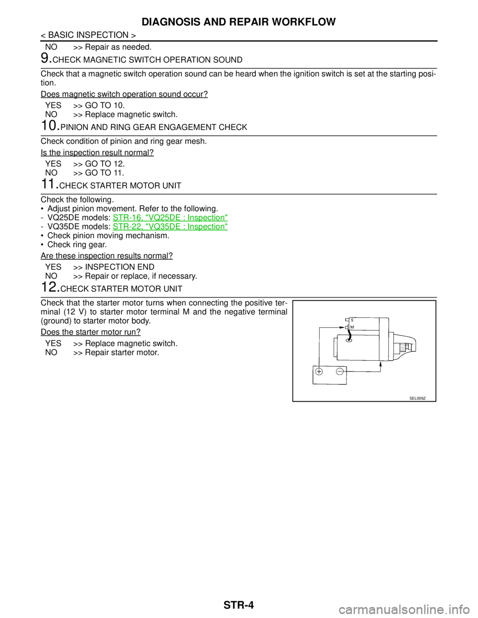
12.CHECK STARTER MOTOR UNIT
Check that the starter motor turns when connecting the positive ter-
minal (12 V) to starter motor terminal M and the negative terminal
(ground) to starter motor body.
Does the starter motor run?
YES >> Replace magnetic switch.
NO >> Repair starter motor.
SEL009Z