2008 NISSAN TEANA maintenance
[x] Cancel search: maintenancePage 3726 of 5121

RAX-1
TRANSMISSION & DRIVELINE
CEF
G H
I
J
K L
M
SECTION RAX
A
B
RAX
N
O P
CONTENTS
REAR AXLE
SYMPTOM DIAGNOSIS ..... ..........................2
NOISE, VIBRATION AND HARSHNESS
(NVH) TROUBLESHOOTING ........................ .....
2
NVH Troubleshooting Chart ................................ ......2
ON-VEHICLE MAINTENANCE .....................3
REAR WHEEL HUB AND HOUSING ............ .....3
Inspection ............................................................ ......3
ON-VEHICLE REPAIR ..................................4
REAR WHEEL HUB AND HOUSING ................4
Exploded View ..................................................... .....4
Removal and Installation ..........................................4
Inspection .................................................................5
SERVICE DATA AND SPECIFICATIONS
(SDS) ............... ..............................................
6
SERVICE DATA AND SPECIFICATIONS
(SDS) ..................................................................
6
Wheel Bearing ..................................................... .....6
Page 3728 of 5121
REAR WHEEL HUB AND HOUSING
RAX-3
< ON-VEHICLE MAINTENANCE >
C
E
F
G
H
I
J
K
L
MA
B
RAX
N
O
P
ON-VEHICLE MAINTENANCE
REAR WHEEL HUB AND HOUSING
InspectionINFOID:0000000003811098
MOUNTING INSPECTION
Make sure the mounting conditions (looseness, back lash) of each component and component conditions
(wear, damage) are normal.
WHEEL BEARING INSPECTION
Move wheel hub and bearing assembly in the axial direction by hand. Make sure there is no looseness of
wheel bearing.
Rotate wheel hub, and make sure there is no unusual noise or other irregular conditions. If there is any of
irregular conditions, replace wheel hub and bearing assembly.Standard
Axial end play : Refer to RAX-6, "
Wheel Bearing".
Page 3808 of 5121
PRECAUTIONS
RF-77
< PRECAUTION >
C
D
E
F
G
H
I
J
L
MA
B
RF
N
O
P
PRECAUTION
PRECAUTIONS
Precaution for Supplemental Restraint System (SRS) "AIR BAG" and "SEAT BELT
PRE-TENSIONER"
INFOID:0000000003940151
The Supplemental Restraint System such as “AIR BAG” and “SEAT BELT PRE-TENSIONER”, used along
with a front seat belt, helps to reduce the risk or severity of injury to the driver and front passenger for certain
types of collision. Information necessary to service the system safely is included in the “SRS AIRBAG” and
“SEAT BELT” of this Service Manual.
WARNING:
To avoid rendering the SRS inoperative, which could increase the risk of personal injury or death in
the event of a collision which would result in air bag inflation, all maintenance must be performed by
an authorized NISSAN/INFINITI dealer.
Improper maintenance, including incorrect removal and installation of the SRS, can lead to personal
injury caused by unintentional activation of the system. For removal of Spiral Cable and Air Bag
Module, see the “SRS AIRBAG”.
Never use electrical test equipment on any circuit related to the SRS unless instructed to in this Ser-
vice Manual. SRS wiring harnesses can be identified by yellow and/or orange harnesses or harness
connectors.
Service NoticeINFOID:0000000003812880
When removing or installing various parts, place a cloth or padding onto the vehicle body to prevent
scratches.
Handle trim, molding, instruments, grille, etc. carefully during removing or installing. Be careful not to oil or
damage them.
Apply sealing compound where necessary when installing parts.
When applying sealing compound, be careful that the sealing compound does not protrude from parts.
When replacing any metal parts (for example body outer panel, members, etc.), be sure to take rust preven-
tion measures.
Precaution for WorkINFOID:0000000003812881
When removing or disassembling each component, be careful not to damage or deform it. If a component
may be subject to interference, be sure to protect it with a shop cloth.
When removing (disengaging) components with a screwdriver or similar tool, be sure to wrap the component
with a shop cloth or vinyl tape to protect it.
Protect the removed parts with a shop cloth and keep them.
Replace a deformed or damaged clip.
If a part is specified as a non-reusable part, always replace it with new one.
Be sure to tighten bolts and nuts securely to the specified torque.
After re-installation is completed, be sure to check that each part works normally.
Follow the steps below to clean components.
- Water soluble foul: Dip a soft cloth into lukewarm water, and wring the water out of the cloth to wipe the
fouled area.
Then rub with a soft and dry cloth.
- Oily foul: Dip a soft cloth into lukewarm water with mild detergent (concentration: within 2 to 3%), and wipe
the fouled area.
Then dip a cloth into fresh water, and wring the water out of the cloth to wipe the detergent off. Then rub with
a soft and dry cloth.
Do not use organic solvent such as thinner, benzene, alcohol, and gasoline.
For genuine leather seats, use a genuine leather seat cleaner.
Page 3833 of 5121

RSU-1
SUSPENSION
C
DF
G H
I
J
K L
M
SECTION RSU
A
B
RSU
N
O PCONTENTS
REAR SUSPENSION
SYMPTOM DIAGNOSIS ..... ..........................2
NOISE, VIBRATION AND HARSHNESS
(NVH) TROUBLESHOOTING ........................ .....
2
NVH Troubleshooting Chart ................................ ......2
PRECAUTION ...............................................3
PRECAUTIONS .............................................. .....3
Precautions for Suspension ................................ ......3
PREPARATION ............................................4
PREPARATION .............................................. .....4
Special Service Tool ........................................... ......4
ON-VEHICLE MAINTENANCE .....................5
REAR SUSPENSION ASSEMBLY ................ .....5
Inspection ............................................................ ......5
WHEEL ALIGNMENT ..........................................6
Inspection ............................................................ ......6
Adjustment ................................................................7
ON-VEHICLE REPAIR ..................................8
REAR LOWER LINK & COIL SPRING .......... .....8
Exploded View .................................................... ......8
Removal and Installation ...........................................8
Inspection ..................................................................9
REAR SHOCK ABSORBER ..............................10
Exploded View .................................................... ....10
Removal and Installation .........................................10
Inspection ................................................................10
RADIUS ROD ................................... .................12
Exploded View ..................................................... ....12
Removal and Installation .........................................12
Inspection ................................................................12
FRONT LOWER LINK .......................................14
Exploded View .........................................................14
Removal and Installation .........................................14
Inspection ................................................................14
REAR STABILIZER ..........................................15
Exploded View .........................................................15
Removal and Installation .........................................15
Inspection ................................................................15
REMOVAL AND INSTALLATION ...............16
REAR SUSPENSION ARM ...............................16
Exploded View ..................................................... ....16
Removal and Installation .........................................16
Inspection ................................................................16
REAR SUSPENSION MEMBER .......................18
Exploded View ..................................................... ....18
Removal and Installation .........................................18
Inspection ................................................................19
SERVICE DATA AND SPECIFICATIONS
(SDS) ............... .............................................
20
SERVICE DATA AND SPECIFICATIONS
(SDS) .................................................................
20
Wheel Alignment ................................................. ....20
Ball Joint ..................................................................20
Wheel Height ...........................................................20
Page 3837 of 5121
REAR SUSPENSION ASSEMBLY
RSU-5
< ON-VEHICLE MAINTENANCE >
C
D
F
G
H
I
J
K
L
MA
B
RSU
N
O
P
ON-VEHICLE MAINTENANCE
REAR SUSPENSION ASSEMBLY
InspectionINFOID:0000000003811139
MOUNTING INSPECTION
Make sure the mounting conditions (looseness, backlash) of each component and component conditions
(wear, damage) are normal.
SHOCK ABSORBER
Check for oil leakage and damage. Replace if necessary.
Page 3838 of 5121
RSU-6
< ON-VEHICLE MAINTENANCE >
WHEEL ALIGNMENT
WHEEL ALIGNMENT
InspectionINFOID:0000000003813442
DESCRIPTION
Measure wheel alignment under unladen conditions.
NOTE:
“Unladen conditions” means that fuel, engine coolant, and lubricant are full. Spare tire, jack, hand tools and
mats are in designated positions.
PRELIMINARY CHECK
Check the following:
Tires for improper air pressure and wear
Road wheels for runout: refer to WT-2, "
Inspection".
Wheel bearing axial end play: refer to RAX-3, "
Inspection".
Shock absorber operation
Each mounting point of axle and suspension for looseness and deformation
Each of lower link, upper link, rear suspension member, suspension arm and shock absorber for cracks,
deformation, and other damage
Vehicle height (posture)
CAMBER
Measure camber of both right and left wheels with a suitable alignment gauge.
If camber is outside specified range, adjust with adjusting bolt in
lower. Refer to RSU-7, "
Adjustment".
TOE-IN
Measure toe-in by the following procedure.
WARNING:
Always perform the following procedure on a flat surface.
Make sure that no person is in front of vehicle before pushing it.
1. Bounce the front of vehicle up and down to stabilize the vehicle height (posture).
2. Push vehicle straight ahead about 5 m (16 ft).
3. Put matching mark (A) on base line of the tread (rear side) of
both tires at the same height of hub center. These are measur-
ing points.Standard
Camber: Refer to RSU-20, "
Wheel Alignment".
SRA096A
JPEIA0014ZZ
Page 3839 of 5121
WHEEL ALIGNMENT
RSU-7
< ON-VEHICLE MAINTENANCE >
C
D
F
G
H
I
J
K
L
MA
B
RSU
N
O
P
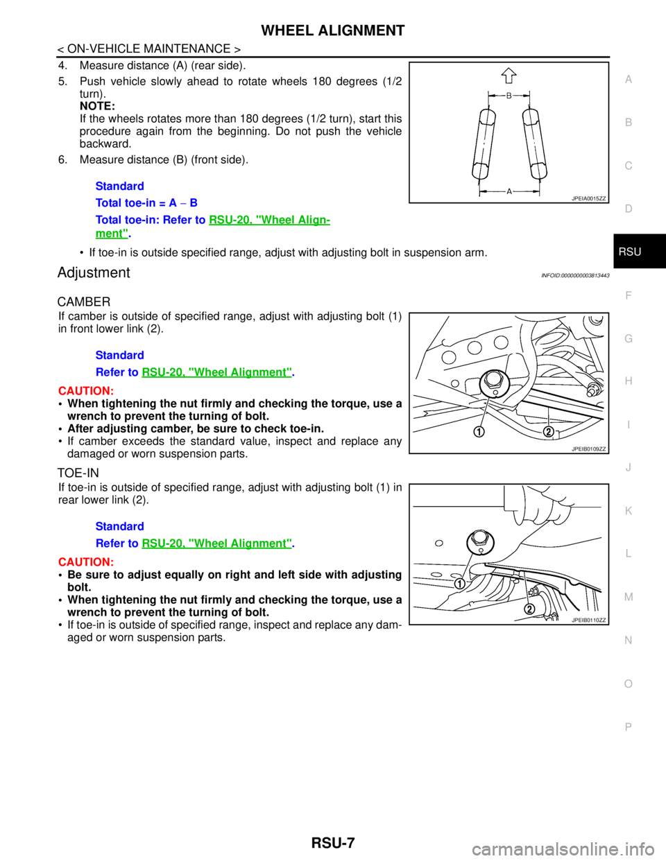
4. Measure distance (A) (rear side).
5. Push vehicle slowly ahead to rotate wheels 180 degrees (1/2
turn).
NOTE:
If the wheels rotates more than 180 degrees (1/2 turn), start this
procedure again from the beginning. Do not push the vehicle
backward.
6. Measure distance (B) (front side).
If toe-in is outside specified range, adjust with adjusting bolt in suspension arm.
AdjustmentINFOID:0000000003813443
CAMBER
If camber is outside of specified range, adjust with adjusting bolt (1)
in front lower link (2).
CAUTION:
When tightening the nut firmly and checking the torque, use a
wrench to prevent the turning of bolt.
After adjusting camber, be sure to check toe-in.
If camber exceeds the standard value, inspect and replace any
damaged or worn suspension parts.
TOE-IN
If toe-in is outside of specified range, adjust with adjusting bolt (1) in
rear lower link (2).
CAUTION:
Be sure to adjust equally on right and left side with adjusting
bolt.
When tightening the nut firmly and checking the torque, use a
wrench to prevent the turning of bolt.
If toe-in is outside of specified range, inspect and replace any dam-
aged or worn suspension parts.Standard
Total toe-in = A − B
Total toe-in: Refer to RSU-20, "
Wheel Align-
ment".
JPEIA0015ZZ
Standard
Refer to RSU-20, "
Wheel Alignment".
JPEIB0109ZZ
Standard
Refer to RSU-20, "
Wheel Alignment".
JPEIB0110ZZ
Page 3854 of 5121
SB-2
< PRECAUTION >
PRECAUTIONS
PRECAUTION
PRECAUTIONS
Precaution for Supplemental Restraint System (SRS) "AIR BAG" and "SEAT BELT
PRE-TENSIONER"
INFOID:0000000003949049
The Supplemental Restraint System such as “AIR BAG” and “SEAT BELT PRE-TENSIONER”, used along
with a front seat belt, helps to reduce the risk or severity of injury to the driver and front passenger for certain
types of collision. Information necessary to service the system safely is included in the “SRS AIRBAG” and
“SEAT BELT” of this Service Manual.
WARNING:
• To avoid rendering the SRS inoperative, which could increase the risk of personal injury or death in
the event of a collision which would result in air bag inflation, all maintenance must be performed by
an authorized NISSAN/INFINITI dealer.
Improper maintenance, including incorrect removal and installation of the SRS, can lead to personal
injury caused by unintentional activation of the system. For removal of Spiral Cable and Air Bag
Module, see the “SRS AIRBAG”.
Never use electrical test equipment on any circuit related to the SRS unless instructed to in this Ser-
vice Manual. SRS wiring harnesses can be identified by yellow and/or orange harnesses or harness
connectors.
Precaution for Seat Belt ServiceINFOID:0000000003848851
CAUTION:
Before removing the front seat belt pre-tensioner assembly, turn the ignition switch OFF, disconnect
both battery cables and wait at least 3 minutes.
Never use electrical test equipment for front seat belt pre-tensioner connector.
After replacing or reinstalling front seat belt pre-tensioner assembly, or reconnecting front seat belt
pre-tensioner connector, check the system function. Refer to SRC-10, "
Diagnosis Description".
Deploy front seat belt pre-tensioner assembly before disposing. Refer to SR-25, "
Caution for Air Bag
Module and Seat Belt Pre-tensioner"
Never use disassembled buckle or seat belt assembly.
Replace anchor bolts if they are deformed or worn out.
Never oil tongue and buckle.
If any component of seat belt assembly is questionable, never repair. Replace the entire seat belt
assembly.
If webbing is cut, frayed or damaged, replace seat belt assembly.
When replacing seat belt assembly, use a Genuine NISSAN seat belt assembly.
AFTER A COLLISION
WARNING:
Inspect all seat belt assemblies including retractors and attached hardware after any collision.
NISSAN recommends that all seat belt assemblies in use during a collision be replaced unless the col-
lision was minor and the belts show no damage and continue to operate properly. Not doing so could
result in serious personal injury in an accident. Seat belt assemblies not in use during a collision
should also be replaced if either damage or improper operation is noted. Seat belt pre-tensioners
should be replaced even if the seat belts are not in use during a frontal collision in which the air bags
are deployed.
Replace any seat belt assembly (including anchor bolts) if:
The seat belt is in use at the time of a collision (except for minor collisions and the belts, retractors and buck-
les show no damage and continue to operate properly).
The seat belt is damaged in an accident (i.e. torn webbing, bent retractor or guide).
The seat belt attaching point is damaged in an accident. Inspect the seat belt attaching area for damage or
distortion and repair as necessary before installing a new seat belt assembly.
Anchor bolts are deformed or worn out.
The front seat belt pre-tensioner must be replaced even if the seat belts are not in use during the collision in
which the air bags are deployed.