2008 NISSAN TEANA water pump
[x] Cancel search: water pumpPage 1711 of 5121
![NISSAN TEANA 2008 Service Manual EC-250
< COMPONENT DIAGNOSIS >[VQ25DE, VQ35DE]
P1217 ENGINE OVER TEMPERATURE
P1217 ENGINE OVER TEMPERATURE
DTC LogicINFOID:0000000003856718
DTC DETECTION LOGIC
NOTE:
If DTC P1217 is displayed with DT NISSAN TEANA 2008 Service Manual EC-250
< COMPONENT DIAGNOSIS >[VQ25DE, VQ35DE]
P1217 ENGINE OVER TEMPERATURE
P1217 ENGINE OVER TEMPERATURE
DTC LogicINFOID:0000000003856718
DTC DETECTION LOGIC
NOTE:
If DTC P1217 is displayed with DT](/manual-img/5/57391/w960_57391-1710.png)
EC-250
< COMPONENT DIAGNOSIS >[VQ25DE, VQ35DE]
P1217 ENGINE OVER TEMPERATURE
P1217 ENGINE OVER TEMPERATURE
DTC LogicINFOID:0000000003856718
DTC DETECTION LOGIC
NOTE:
If DTC P1217 is displayed with DTC U1000 or U1001, first perform the trouble diagnosis for DTC
U1000, U1001. Refer to EC-135, "
DTC Logic".
If DTC P1217 is displayed with DTC P0607, first perform the trouble diagnosis for DTC P0607. Refer
to EC-242, "
DTC Logic".
If the cooling fan or another component in the cooling system malfunctions, engine coolant temperature will
rise.
When the engine coolant temperature reaches an abnormally high temperature condition, a malfunction is
indicated.
CAUTION:
When a malfunction is indicated, always replace the coolant. Refer to CO-8, "
Draining". Also, replace
the engine oil. Refer to LU-8, "
Draining".
1. Fill radiator with coolant up to specified level with a filling speed of 2 liters per minute. Always use
coolant with the proper mixture ratio. Refer to MA-12, "
Engine Coolant Mixture Ratio".
2. After refilling coolant, run engine to ensure that no water-flow noise is emitted.
DTC CONFIRMATION PROCEDURE
1.PERFORM COMPONENT FUNCTION CHECK
Perform component function check. Refer to EC-250, "
Component Function Check".
NOTE:
Use component function check to check the overall function of the cooling fan. During this check, a DTC might
not be confirmed.
Is the inspection result normal?
YES >> INSPECTION END
NO >> Go to EC-251, "
Diagnosis Procedure".
Component Function CheckINFOID:0000000003856719
1.PERFORM COMPONENT FUNCTION CHECK-I
WARNING:
Never remove the radiator cap when the engine is hot. Serious burns could be caused by high pres-
sure fluid escaping from the radiator.
Wrap a thick cloth around cap. Carefully remove the cap by turning it a quarter turn to allow built-up
pressure to escape. Then turn the cap all the way off.
DTC No. Trouble diagnosis name DTC detecting condition Possible cause
P1217Engine over tempera-
ture (Overheat) Cooling fan does not operate properly (Over-
heat).
Cooling fan system does not operate proper-
ly (Overheat).
Engine coolant was not added to the system
using the proper filling method.
Engine coolant is not within the specified
range. Harness or connectors
(The cooling fan circuit is open or short-
ed.)
IPDM E/R (Cooling fan relays)
Cooling fan motor
Radiator hose
Radiator
Radiator cap
Water pump
Thermostat
Page 1712 of 5121
![NISSAN TEANA 2008 Service Manual P1217 ENGINE OVER TEMPERATURE
EC-251
< COMPONENT DIAGNOSIS >[VQ25DE, VQ35DE]
C
D
E
F
G
H
I
J
K
L
MA
EC
N
P O
Check the coolant level in the reservoir tank and radiator.
Allow engine to cool before che NISSAN TEANA 2008 Service Manual P1217 ENGINE OVER TEMPERATURE
EC-251
< COMPONENT DIAGNOSIS >[VQ25DE, VQ35DE]
C
D
E
F
G
H
I
J
K
L
MA
EC
N
P O
Check the coolant level in the reservoir tank and radiator.
Allow engine to cool before che](/manual-img/5/57391/w960_57391-1711.png)
P1217 ENGINE OVER TEMPERATURE
EC-251
< COMPONENT DIAGNOSIS >[VQ25DE, VQ35DE]
C
D
E
F
G
H
I
J
K
L
MA
EC
N
P O
Check the coolant level in the reservoir tank and radiator.
Allow engine to cool before checking coolant level.
Is the coolant level in the reservoir tank and/or radiator below the
proper range?
YES >> Go to EC-251, "Diagnosis Procedure".
NO >> GO TO 2.
2.PERFORM COMPONENT FUNCTION CHECK-II
Confirm whether customer filled the coolant or not.
Did customer fill the coolant?
YES >> Go to EC-251, "Diagnosis Procedure".
NO >> GO TO 3.
3.PERFORM COMPONENT FUNCTION CHECK-III
With CONSULT-III
1. Turn ignition switch ON.
2. Perform “COOLING FAN” in “ACTIVE TEST” mode with CONSULT-III.
3. Check that cooling fan motors-1 and -2 operate at each speed (LOW/MID/HI).
Without CONSULT-III
Perform IPDM E/R auto active test and check cooling fan motors operation, refer to PCS-11, "
Diagnosis
Description".
Is the inspection result normal?
YES >> INSPECTION END
NO >> Go to EC-251, "
Diagnosis Procedure".
Diagnosis ProcedureINFOID:0000000003856720
1.CHECK COOLING FAN OPERATION
With CONSULT-III
1. Turn ignition switch ON.
2. Perform “COOLING FAN” in “ACTIVE TEST” mode with CONSULT-III.
3. Check that cooling fans-1 and -2 operate at each speed (LOW/MID/HI).
Without CONSULT-III
1. Perform IPDM E/R auto active test and check cooling fan motors operation, refer to PCS-11, "
Diagnosis
Description".
2. Check that cooling fans-1 and -2 operate at each speed (Low/Middle/High).
Is the inspection result normal?
YES >> GO TO 2.
NO >> Go to EC-324, "
Diagnosis Procedure".
2.CHECK COOLING SYSTEM FOR LEAK-I
Check cooling system for leak. Refer to CO-8, "
Inspection".
Is leakage detected?
YES >> GO TO 3.
NO >> GO TO 4.
3.CHECK COOLING SYSTEM FOR LEAK-II
Check the following for leak.
Hose
Radiator
Water pump
SEF621W
Page 1861 of 5121
![NISSAN TEANA 2008 Service Manual EC-400
< SYMPTOM DIAGNOSIS >[VQ25DE, VQ35DE]
ENGINE CONTROL SYSTEM SYMPTOMS
SYMPTOM DIAGNOSIS
ENGINE CONTROL SYSTEM SYMPTOMS
Symptom TableINFOID:0000000003856875
SYSTEM — BASIC ENGINE CONTROL SYSTEM NISSAN TEANA 2008 Service Manual EC-400
< SYMPTOM DIAGNOSIS >[VQ25DE, VQ35DE]
ENGINE CONTROL SYSTEM SYMPTOMS
SYMPTOM DIAGNOSIS
ENGINE CONTROL SYSTEM SYMPTOMS
Symptom TableINFOID:0000000003856875
SYSTEM — BASIC ENGINE CONTROL SYSTEM](/manual-img/5/57391/w960_57391-1860.png)
EC-400
< SYMPTOM DIAGNOSIS >[VQ25DE, VQ35DE]
ENGINE CONTROL SYSTEM SYMPTOMS
SYMPTOM DIAGNOSIS
ENGINE CONTROL SYSTEM SYMPTOMS
Symptom TableINFOID:0000000003856875
SYSTEM — BASIC ENGINE CONTROL SYSTEM
SYMPTOM
Reference
page
HARD/NO START/RESTART (EXCP. HA)
ENGINE STALL
HESITATION/SURGING/FLAT SPOT
SPARK KNOCK/DETONATION
LACK OF POWER/POOR ACCELERATION
HIGH IDLE/LOW IDLE
ROUGH IDLE/HUNTING
IDLING VIBRATION
SLOW/NO RETURN TO IDLE
OVERHEATS/WATER TEMPERATURE HIGH
EXCESSIVE FUEL CONSUMPTION
EXCESSIVE OIL CONSUMPTION
BATTERY DEAD (UNDER CHARGE)
Warranty symptom code AA AB AC AD AE AF AG AH AJ AK AL AM HA
Fuel Fuel pump circuit 11232 22 3 2EC-337
Fuel pressure regulator system 334444444 4EC-411
Fuel injector circuit 11232 22 2EC-334
Evaporative emission system 334444444 4EC-76
Air Positive crankcase ventilation sys-
tem
334444444 41EC-347
Incorrect idle speed adjustment 1 1 1 1 1EC-11
Electric throttle control actuator 112332222 2 2EC-296,
EC-302
IgnitionIncorrect ignition timing adjustment33111 11 1EC-11
Ignition circuit 11222 22 2EC-341
Power supply and ground circuit 22333 33 23EC-132
Mass air flow sensor circuit
1
122
222 2EC-149
Engine coolant temperature sensor circuit
333EC-157
Air fuel ratio (A/F) sensor 1 circuitEC-163
,
EC-167
,
EC-170
,
EC-173
,
EC-318
Throttle position sensor circuit
22EC-160
,
EC-206
,
EC-254
,
EC-256
,
EC-311
Accelerator pedal position sensor circuit 3 2 1EC-243
,
EC-304
,
EC-307
,
EC-314
Knock sensor circuit 2 3EC-215
Page 1864 of 5121
![NISSAN TEANA 2008 Service Manual ENGINE CONTROL SYSTEM SYMPTOMS
EC-403
< SYMPTOM DIAGNOSIS >[VQ25DE, VQ35DE]
C
D
E
F
G
H
I
J
K
L
MA
EC
N
P O
1 - 6: The numbers refer to the order of inspection.Va l v e
mecha-
nismTiming chain
55555 NISSAN TEANA 2008 Service Manual ENGINE CONTROL SYSTEM SYMPTOMS
EC-403
< SYMPTOM DIAGNOSIS >[VQ25DE, VQ35DE]
C
D
E
F
G
H
I
J
K
L
MA
EC
N
P O
1 - 6: The numbers refer to the order of inspection.Va l v e
mecha-
nismTiming chain
55555](/manual-img/5/57391/w960_57391-1863.png)
ENGINE CONTROL SYSTEM SYMPTOMS
EC-403
< SYMPTOM DIAGNOSIS >[VQ25DE, VQ35DE]
C
D
E
F
G
H
I
J
K
L
MA
EC
N
P O
1 - 6: The numbers refer to the order of inspection.Va l v e
mecha-
nismTiming chain
55555 55 5EM-65
CamshaftEM-84
Intake valve timing controlEM-65
Intake valve
3EM-97
Exhaust valve
Exhaust Exhaust manifold/Tube/Muffler/
Gasket
55555 55 5EM-34
, EX-
4Three way catalyst
Lubrica-
tionOil pan/Oil strainer/Oil pump/Oil
filter/Oil gallery/Oil cooler
55555 55 5LU-7
, LU-
10, LU-11,
LU-13
Oil level (Low)/Filthy oilLU-7
Cooling
Radiator/Hose/Radiator filler cap
55555 55 45CO-12,
CO-12
Thermostat 5CO-23
Water pumpCO-18
Water galleryCO-2
Cooling fan
5CO-16
Coolant level (Low)/Contaminat-
ed coolantCO-8
NVIS (NISSAN Vehicle Immobilizer System —
NATS)11SEC-14
SYMPTOM
Reference
page
HARD/NO START/RESTART (EXCP. HA)
ENGINE STALL
HESITATION/SURGING/FLAT SPOT
SPARK KNOCK/DETONATION
LACK OF POWER/POOR ACCELERATION
HIGH IDLE/LOW IDLE
ROUGH IDLE/HUNTING
IDLING VIBRATION
SLOW/NO RETURN TO IDLE
OVERHEATS/WATER TEMPERATURE HIGH
EXCESSIVE FUEL CONSUMPTION
EXCESSIVE OIL CONSUMPTION
BATTERY DEAD (UNDER CHARGE)
Warranty symptom code AA AB AC AD AE AF AG AH AJ AK AL AM HA
Page 1879 of 5121

EM-4
< SYMPTOM DIAGNOSIS >
NOISE, VIBRATION AND HARSHNESS (NVH) TROUBLESHOOTING
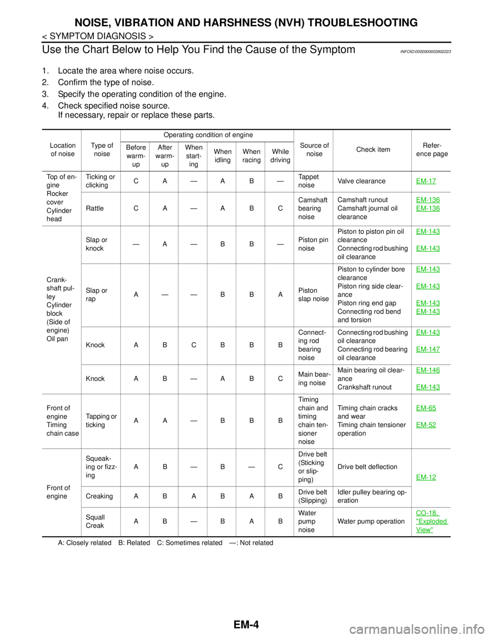
Use the Chart Below to Help You Find the Cause of the Symptom
INFOID:0000000003802223
1. Locate the area where noise occurs.
2. Confirm the type of noise.
3. Specify the operating condition of the engine.
4. Check specified noise source.
If necessary, repair or replace these parts.
A: Closely related B: Related C: Sometimes related —: Not related Location
of noiseType of
noiseOperating condition of engine
Source of
noiseCheck itemRefer-
ence page Before
warm-
upAfter
warm-
upWhen
start-
ingWhen
idlingWhen
racingWhile
driving
Top of en-
gine
Rocker
cover
Cylinder
headTicking or
clickingCA—AB—Tappet
noiseValve clearanceEM-17
Rattle C A — A B CCamshaft
bearing
noiseCamshaft runout
Camshaft journal oil
clearanceEM-136EM-136
Crank-
shaft pul-
ley
Cylinder
block
(Side of
engine)
Oil panSlap or
knock—A—B B—Piston pin
noisePiston to piston pin oil
clearance
Connecting rod bushing
oil clearanceEM-143
EM-143
Slap or
rapA——B B APiston
slap noisePiston to cylinder bore
clearance
Piston ring side clear-
ance
Piston ring end gap
Connecting rod bend
and torsionEM-143EM-143
EM-143
EM-143
Knock A B C B B BConnect-
ing rod
bearing
noiseConnecting rod bushing
oil clearance
Connecting rod bearing
oil clearanceEM-143EM-147
Knock A B — A B CMain bear-
ing noiseMain bearing oil clear-
ance
Crankshaft runoutEM-146
EM-143
Front of
engine
Timing
chain caseTapping or
tickingAA—BBBTiming
chain and
timing
chain ten-
sioner
noiseTiming chain cracks
and wear
Timing chain tensioner
operationEM-65
EM-52
Front of
engineSqueak-
ing or fizz-
ingAB—B—CDrive belt
(Sticking
or slip-
ping)Drive belt deflection
EM-12
CreakingABABABDrive belt
(Slipping)Idler pulley bearing op-
eration
Squall
CreakAB—BABWater
pump
noiseWater pump operationCO-18,
"Exploded
View"
Page 1888 of 5121

DRIVE BELT
EM-13
< ON-VEHICLE MAINTENANCE >
C
D
E
F
G
H
I
J
K
L
MA
EM
N
P O
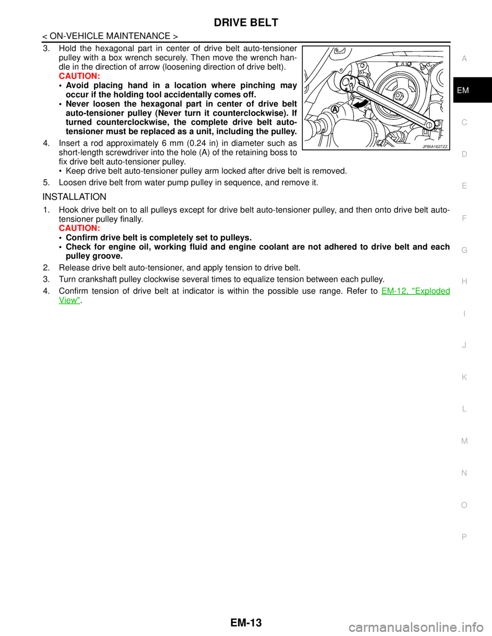
3. Hold the hexagonal part in center of drive belt auto-tensioner
pulley with a box wrench securely. Then move the wrench han-
dle in the direction of arrow (loosening direction of drive belt).
CAUTION:
Avoid placing hand in a location where pinching may
occur if the holding tool accidentally comes off.
Never loosen the hexagonal part in center of drive belt
auto-tensioner pulley (Never turn it counterclockwise). If
turned counterclockwise, the complete drive belt auto-
tensioner must be replaced as a unit, including the pulley.
4. Insert a rod approximately 6 mm (0.24 in) in diameter such as
short-length screwdriver into the hole (A) of the retaining boss to
fix drive belt auto-tensioner pulley.
Keep drive belt auto-tensioner pulley arm locked after drive belt is removed.
5. Loosen drive belt from water pump pulley in sequence, and remove it.
INSTALLATION
1. Hook drive belt on to all pulleys except for drive belt auto-tensioner pulley, and then onto drive belt auto-
tensioner pulley finally.
CAUTION:
Confirm drive belt is completely set to pulleys.
Check for engine oil, working fluid and engine coolant are not adhered to drive belt and each
pulley groove.
2. Release drive belt auto-tensioner, and apply tension to drive belt.
3. Turn crankshaft pulley clockwise several times to equalize tension between each pulley.
4. Confirm tension of drive belt at indicator is within the possible use range. Refer to EM-12, "
Exploded
View".
JPBIA1627ZZ
Page 1928 of 5121

TIMING CHAIN
EM-53
< ON-VEHICLE REPAIR >
C
D
E
F
G
H
I
J
K
L
MA
EM
N
P O
Removal and InstallationINFOID:0000000003802270
REMOVAL
1. Drain engine oil. Refer to LU-8, "Draining".
2. Drain engine coolant from inside engine. Refer to EM-76, "
Setting".
3. Remove intake manifold collector. Refer to EM-28, "
Exploded View".
4. Remove rocker covers (bank 1 and bank 2). Refer to EM-49, "
Exploded View".
5. Remove oil pans (lower and upper) and oil strainer. Refer to EM-38, "
Exploded View".
6. Remove drive belt, idler pulleys and bracket. Refer to EM-12, "
Removal and Installation" and EM-25,
"Exploded View".
7. Separate engine harness removing their brackets from front timing chain case.
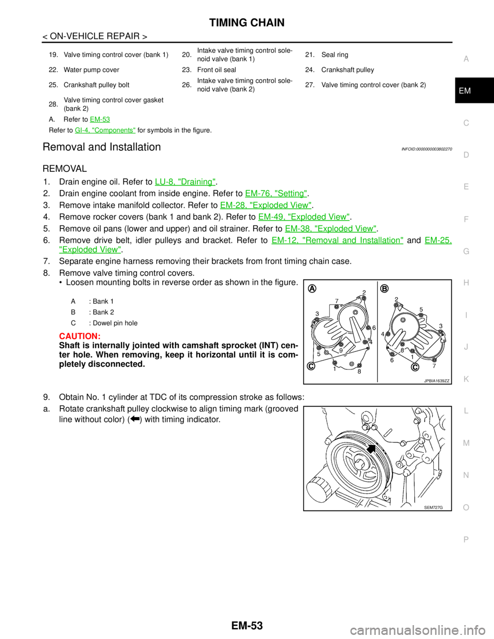
8. Remove valve timing control covers.
Loosen mounting bolts in reverse order as shown in the figure.
CAUTION:
Shaft is internally jointed with camshaft sprocket (INT) cen-
ter hole. When removing, keep it horizontal until it is com-
pletely disconnected.
9. Obtain No. 1 cylinder at TDC of its compression stroke as follows:
a. Rotate crankshaft pulley clockwise to align timing mark (grooved
line without color) ( ) with timing indicator.
19. Valve timing control cover (bank 1) 20.Intake valve timing control sole-
noid valve (bank 1)21. Seal ring
22. Water pump cover 23. Front oil seal 24. Crankshaft pulley
25. Crankshaft pulley bolt 26.Intake valve timing control sole-
noid valve (bank 2)27. Valve timing control cover (bank 2)
28.Valve timing control cover gasket
(bank 2)
A. Refer to EM-53
Refer to GI-4, "Components" for symbols in the figure.
A: Bank 1
B: Bank 2
C : Dowel pin hole
JPBIA1639ZZ
SEM727G
Page 1930 of 5121

TIMING CHAIN
EM-55
< ON-VEHICLE REPAIR >
C
D
E
F
G
H
I
J
K
L
MA
EM
N
P O
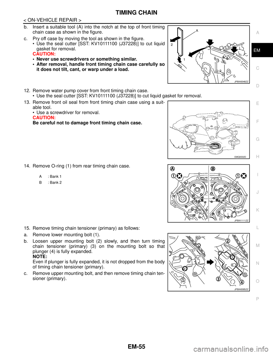
b. Insert a suitable tool (A) into the notch at the top of front timing
chain case as shown in the figure.
c. Pry off case by moving the tool as shown in the figure.
Use the seal cutter [SST: KV10111100 (J37228)] to cut liquid
gasket for removal.
CAUTION:
Never use screwdrivers or something similar.
After removal, handle front timing chain case carefully so
it does not tilt, cant, or warp under a load.
12. Remove water pump cover from front timing chain case.
Use the seal cutter [SST: KV10111100 (J37228)] to cut liquid gasket for removal.
13. Remove front oil seal from front timing chain case using a suit-
able tool.
Use a screwdriver for removal.
CAUTION:
Be careful not to damage front timing chain case.
14. Remove O-ring (1) from rear timing chain case.
15. Remove timing chain tensioner (primary) as follows:
a. Remove lower mounting bolt (1).
b. Loosen upper mounting bolt (2) slowly, and then turn timing
chain tensioner (primary) (3) on the mounting bolt so that
plunger (4) is fully expanded.
NOTE:
Even if plunger is fully expanded, it is not dropped from the body
of timing chain tensioner (primary).
c. Remove upper mounting bolt, and then remove timing chain ten-
sioner (primary).
JPBIA0048ZZ
EMQ0032D
A: Bank 1
B: Bank 2
JPBIA1111ZZ
JPBIA0085ZZ