2008 NISSAN TEANA water pump
[x] Cancel search: water pumpPage 1933 of 5121
EM-58
< ON-VEHICLE REPAIR >
TIMING CHAIN
21. Use a scraper to remove all traces of old liquid gasket from
water pump cover.
INSTALLATION
NOTE:
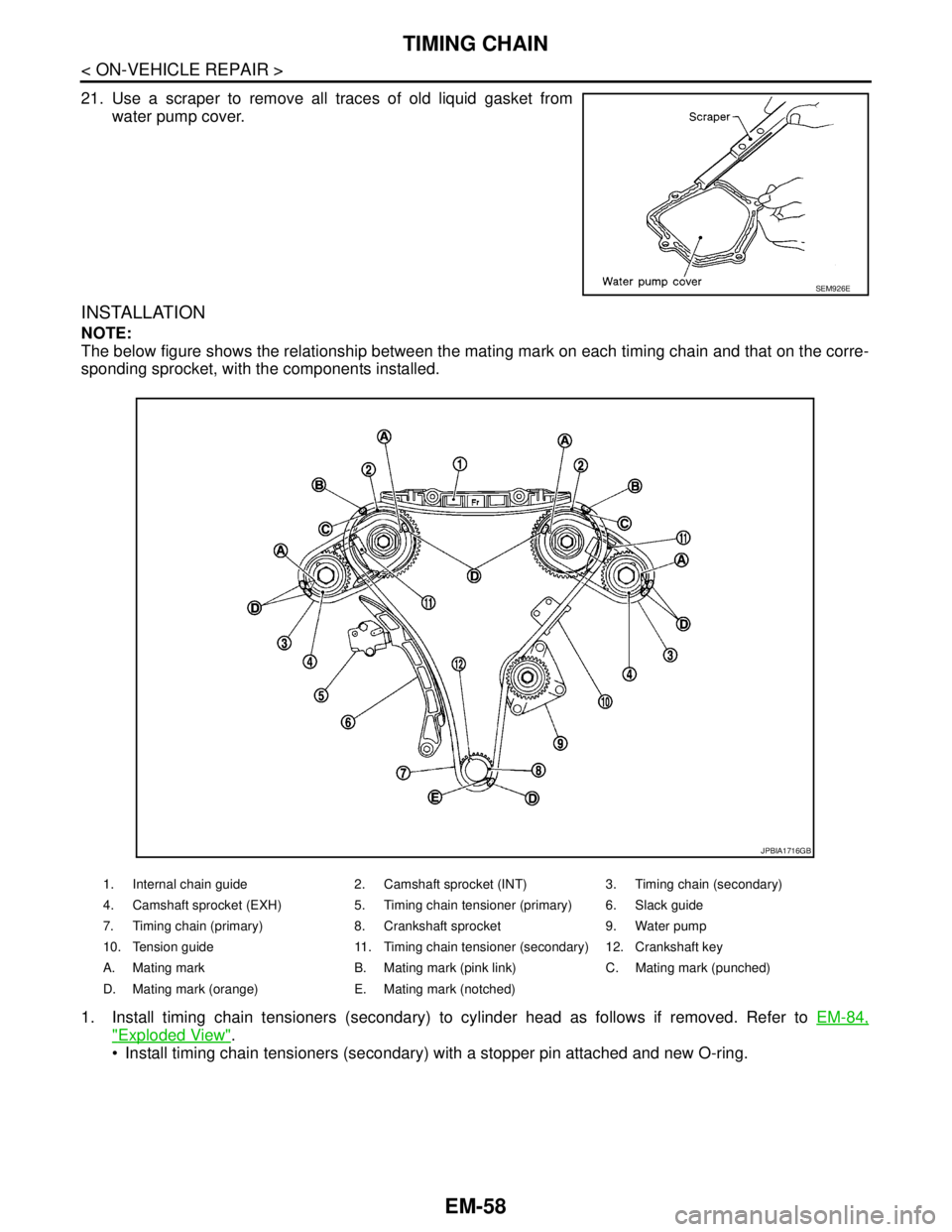
The below figure shows the relationship between the mating mark on each timing chain and that on the corre-
sponding sprocket, with the components installed.
1. Install timing chain tensioners (secondary) to cylinder head as follows if removed. Refer to EM-84,
"Exploded View".
Install timing chain tensioners (secondary) with a stopper pin attached and new O-ring.
SEM926E
1. Internal chain guide 2. Camshaft sprocket (INT) 3. Timing chain (secondary)
4. Camshaft sprocket (EXH) 5. Timing chain tensioner (primary) 6. Slack guide
7. Timing chain (primary) 8. Crankshaft sprocket 9. Water pump
10. Tension guide 11. Timing chain tensioner (secondary) 12. Crankshaft key
A. Mating mark B. Mating mark (pink link) C. Mating mark (punched)
D. Mating mark (orange) E. Mating mark (notched)
JPBIA1716GB
Page 1938 of 5121
TIMING CHAIN
EM-63
< ON-VEHICLE REPAIR >
C
D
E
F
G
H
I
J
K
L
MA
EM
N
P O
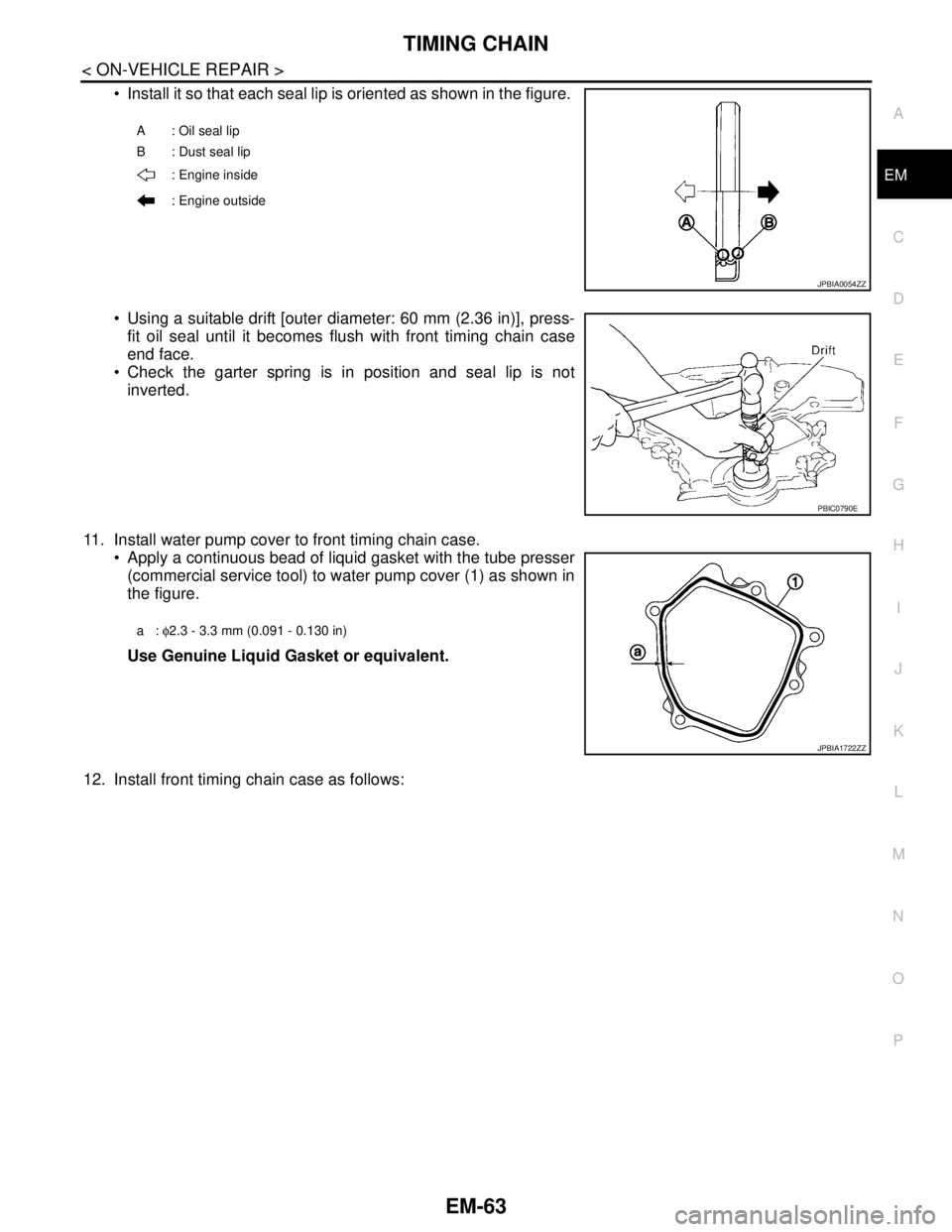
Install it so that each seal lip is oriented as shown in the figure.
Using a suitable drift [outer diameter: 60 mm (2.36 in)], press-
fit oil seal until it becomes flush with front timing chain case
end face.
Check the garter spring is in position and seal lip is not
inverted.
11. Install water pump cover to front timing chain case.
Apply a continuous bead of liquid gasket with the tube presser
(commercial service tool) to water pump cover (1) as shown in
the figure.
Use Genuine Liquid Gasket or equivalent.
12. Install front timing chain case as follows:
A: Oil seal lip
B : Dust seal lip
: Engine inside
: Engine outside
JPBIA0054ZZ
PBIC0790E
a: φ2.3 - 3.3 mm (0.091 - 0.130 in)
JPBIA1722ZZ
Page 1955 of 5121
EM-80
< DISASSEMBLY AND ASSEMBLY >
REAR TIMING CHAIN CASE
Disassembly and Assembly
INFOID:0000000003802282
DISASSEMBLY
1. Remove front timing chain case and timing chain. Refer to EM-52, "Exploded View".
2. Remove water pump. Refer to CO-18, "
Exploded View".
3. Remove oil pans (upper and lower) and oil strainer. Refer to EM-38, "
Exploded View".
4. Remove rear timing chain case as follows:
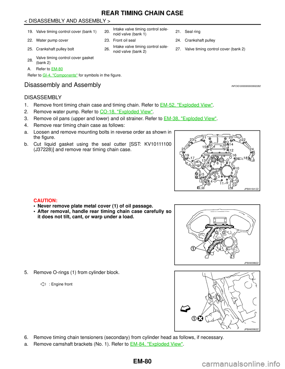
a. Loosen and remove mounting bolts in reverse order as shown in
the figure.
b . C u t l i q u i d g a s k e t u s i n g t h e s e a l c u t t e r [ S S T: K V 1 0 1111 0 0
(J37228)] and remove rear timing chain case.
CAUTION:
Never remove plate metal cover (1) of oil passage.
After removal, handle rear timing chain case carefully so
it does not tilt, cant, or warp under a load.
5. Remove O-rings (1) from cylinder block.
6. Remove timing chain tensioners (secondary) from cylinder head as follows, if necessary.
a. Remove camshaft brackets (No. 1). Refer to EM-84, "
Exploded View".
19. Valve timing control cover (bank 1) 20.Intake valve timing control sole-
noid valve (bank 1)21. Seal ring
22. Water pump cover 23. Front oil seal 24. Crankshaft pulley
25. Crankshaft pulley bolt 26.Intake valve timing control sole-
noid valve (bank 2)27. Valve timing control cover (bank 2)
28.Valve timing control cover gasket
(bank 2)
A. Refer to EM-80
Refer to GI-4, "Components" for symbols in the figure.
JPBIA1641ZZ
JPBIA0088ZZ
: Engine front
JPBIA0090ZZ
Page 1957 of 5121
EM-82
< DISASSEMBLY AND ASSEMBLY >
REAR TIMING CHAIN CASE
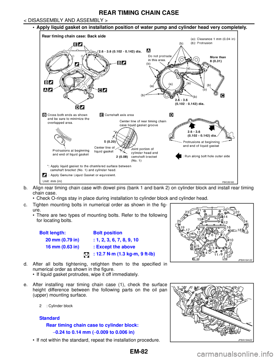
Apply liquid gasket on installation position of water pump and cylinder head very completely.
b. Align rear timing chain case with dowel pins (bank 1 and bank 2) on cylinder block and install rear timing
chain case.
Check O-rings stay in place during installation to cylinder block and cylinder head.
c. Tighten mounting bolts in numerical order as shown in the fig-
ure.
There are two types of mounting bolts. Refer to the following
for locating bolts.
d. After all bolts tightening, retighten them to the specified in
numerical order as shown in the figure.
If liquid gasket protrudes, wipe it off immediately.
e. After installing rear timing chain case (1), check the surface
height difference between the following parts on the oil pan
(upper) mounting surface.
If not within the standard, repeat the installation procedure.Bolt length: Bolt position
20 mm (0.79 in) : 1, 2, 3, 6, 7, 8, 9, 10
16 mm (0.63 in) : Except the above
: 12.7 N·m (1.3 kg-m, 9 ft-lb)
PBIC2616E
JPBIA1641ZZ
2 : Cylinder block
Standard
Rear timing chain case to cylinder block:
−0.24 to 0.14 mm (−0.009 to 0.006 in)
JPBIA1944ZZ
Page 1958 of 5121
REAR TIMING CHAIN CASE
EM-83
< DISASSEMBLY AND ASSEMBLY >
C
D
E
F
G
H
I
J
K
L
MA
EM
N
P O
2. Install water pump with new O-rings. Refer to CO-18, "Exploded View".
3. Install front timing chain case and timing chain. Refer to EM-52, "
Exploded View".
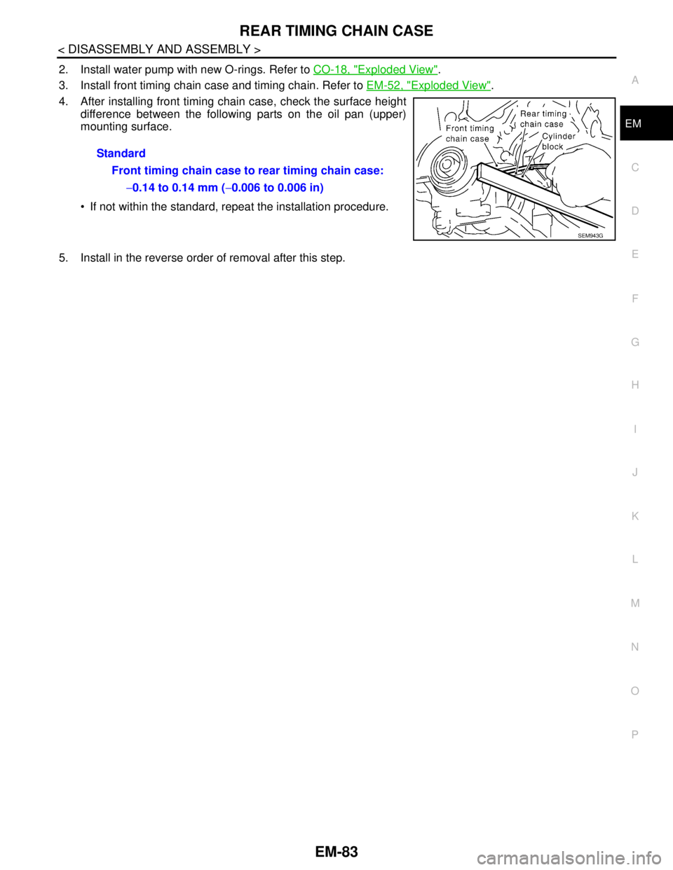
4. After installing front timing chain case, check the surface height
difference between the following parts on the oil pan (upper)
mounting surface.
If not within the standard, repeat the installation procedure.
5. Install in the reverse order of removal after this step.Standard
Front timing chain case to rear timing chain case:
−0.14 to 0.14 mm (−0.006 to 0.006 in)
SEM943G
Page 2519 of 5121
GI-26
< PRECAUTION >
PRECAUTIONS
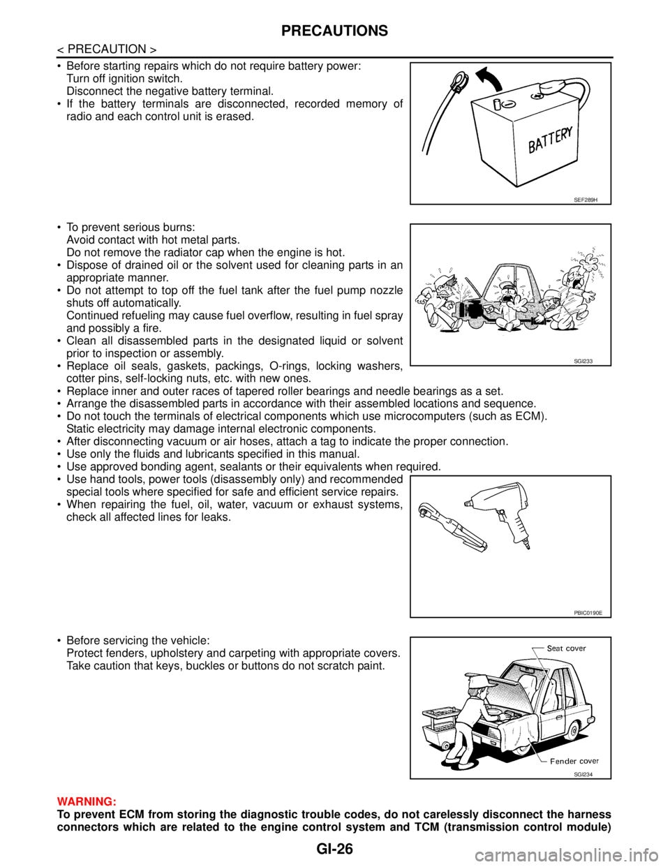
Before starting repairs which do not require battery power:
Turn off ignition switch.
Disconnect the negative battery terminal.
If the battery terminals are disconnected, recorded memory of
radio and each control unit is erased.
To prevent serious burns:
Avoid contact with hot metal parts.
Do not remove the radiator cap when the engine is hot.
Dispose of drained oil or the solvent used for cleaning parts in an
appropriate manner.
Do not attempt to top off the fuel tank after the fuel pump nozzle
shuts off automatically.
Continued refueling may cause fuel overflow, resulting in fuel spray
and possibly a fire.
Clean all disassembled parts in the designated liquid or solvent
prior to inspection or assembly.
Replace oil seals, gaskets, packings, O-rings, locking washers,
cotter pins, self-locking nuts, etc. with new ones.
Replace inner and outer races of tapered roller bearings and needle bearings as a set.
Arrange the disassembled parts in accordance with their assembled locations and sequence.
Do not touch the terminals of electrical components which use microcomputers (such as ECM).
Static electricity may damage internal electronic components.
After disconnecting vacuum or air hoses, attach a tag to indicate the proper connection.
Use only the fluids and lubricants specified in this manual.
Use approved bonding agent, sealants or their equivalents when required.
Use hand tools, power tools (disassembly only) and recommended
special tools where specified for safe and efficient service repairs.
When repairing the fuel, oil, water, vacuum or exhaust systems,
check all affected lines for leaks.
Before servicing the vehicle:
Protect fenders, upholstery and carpeting with appropriate covers.
Take caution that keys, buckles or buttons do not scratch paint.
WARNING:
To prevent ECM from storing the diagnostic trouble codes, do not carelessly disconnect the harness
connectors which are related to the engine control system and TCM (transmission control module)
SEF289H
SGI233
PBIC0190E
SGI234
Page 2559 of 5121
GW-16
< ON-VEHICLE REPAIR >
REAR WINDOW GLASS
3. Remove rear parcel shelf finisher. Refer to INT-43, "Removal and Installation".
4. Remove partially the headlining assembly (rear edge). Refer to INT-50, "
NORMAL ROOF : Removal and
Installation"for normal roof and to INT-54, "SUNROOF : Removal and Installation" for sunroof.
5. Remove connectors and ground from the rear window defogger.
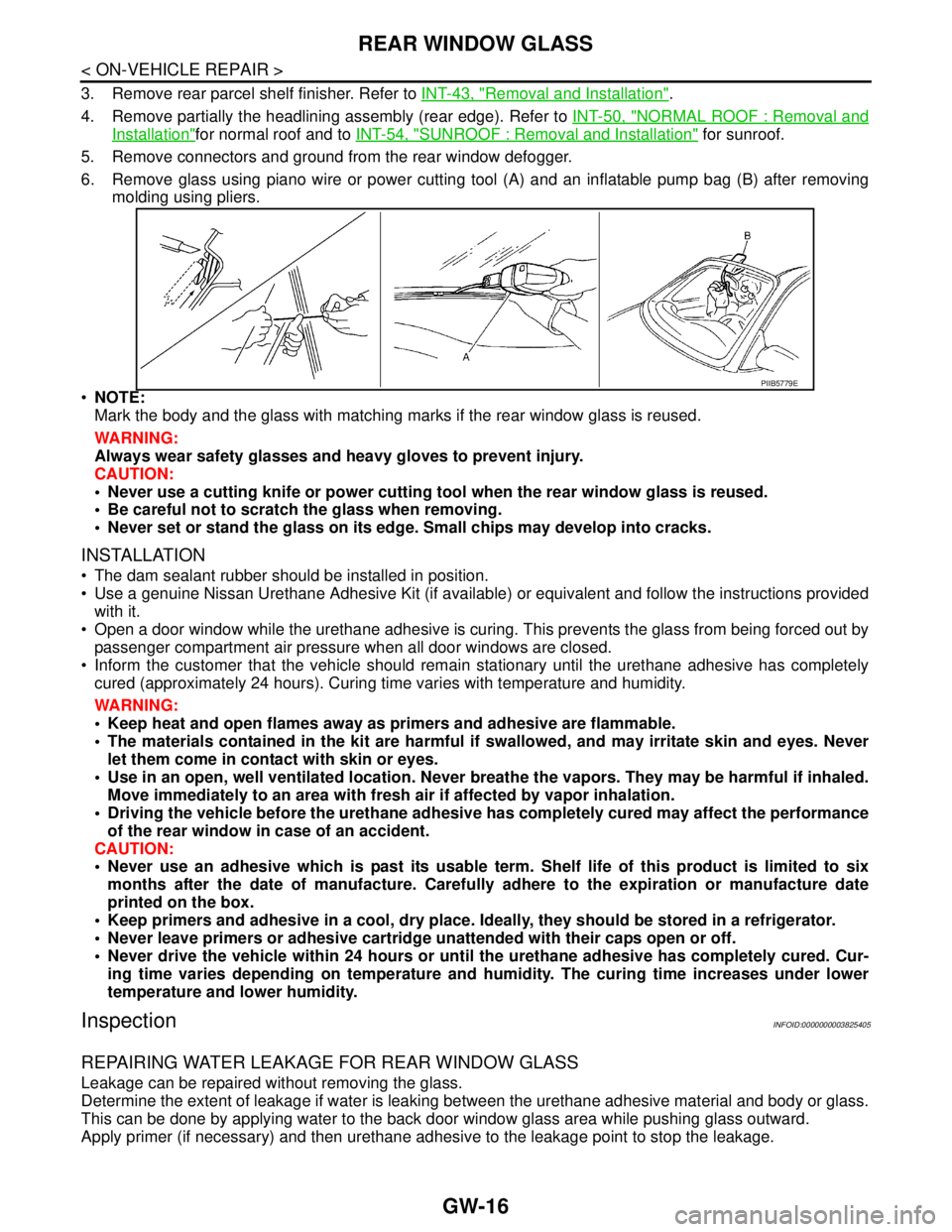
6. Remove glass using piano wire or power cutting tool (A) and an inflatable pump bag (B) after removing
molding using pliers.
NOTE:
Mark the body and the glass with matching marks if the rear window glass is reused.
WARNING:
Always wear safety glasses and heavy gloves to prevent injury.
CAUTION:
Never use a cutting knife or power cutting tool when the rear window glass is reused.
Be careful not to scratch the glass when removing.
Never set or stand the glass on its edge. Small chips may develop into cracks.
INSTALLATION
The dam sealant rubber should be installed in position.
Use a genuine Nissan Urethane Adhesive Kit (if available) or equivalent and follow the instructions provided
with it.
Open a door window while the urethane adhesive is curing. This prevents the glass from being forced out by
passenger compartment air pressure when all door windows are closed.
Inform the customer that the vehicle should remain stationary until the urethane adhesive has completely
cured (approximately 24 hours). Curing time varies with temperature and humidity.
WARNING:
Keep heat and open flames away as primers and adhesive are flammable.
The materials contained in the kit are harmful if swallowed, and may irritate skin and eyes. Never
let them come in contact with skin or eyes.
Use in an open, well ventilated location. Never breathe the vapors. They may be harmful if inhaled.
Move immediately to an area with fresh air if affected by vapor inhalation.
Driving the vehicle before the urethane adhesive has completely cured may affect the performance
of the rear window in case of an accident.
CAUTION:
Never use an adhesive which is past its usable term. Shelf life of this product is limited to six
months after the date of manufacture. Carefully adhere to the expiration or manufacture date
printed on the box.
Keep primers and adhesive in a cool, dry place. Ideally, they should be stored in a refrigerator.
Never leave primers or adhesive cartridge unattended with their caps open or off.
Never drive the vehicle within 24 hours or until the urethane adhesive has completely cured. Cur-
ing time varies depending on temperature and humidity. The curing time increases under lower
temperature and lower humidity.
InspectionINFOID:0000000003825405
REPAIRING WATER LEAKAGE FOR REAR WINDOW GLASS
Leakage can be repaired without removing the glass.
Determine the extent of leakage if water is leaking between the urethane adhesive material and body or glass.
This can be done by applying water to the back door window glass area while pushing glass outward.
Apply primer (if necessary) and then urethane adhesive to the leakage point to stop the leakage.
PIIB5779E
Page 3179 of 5121
ENGINE OIL
LU-7
< ON-VEHICLE MAINTENANCE >
C
D
E
F
G
H
I
J
K
L
MA
LU
N
P O
ON-VEHICLE MAINTENANCE
ENGINE OIL
InspectionINFOID:0000000003793121
ENGINE OIL LEVEL
NOTE:
Before starting engine, put vehicle horizontally and check the engine oil level. If engine is already started, stop
it and allow 10 minutes before checking.
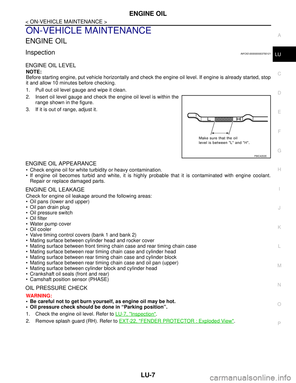
1. Pull out oil level gauge and wipe it clean.
2. Insert oil level gauge and check the engine oil level is within the
range shown in the figure.
3. If it is out of range, adjust it.
ENGINE OIL APPEARANCE
Check engine oil for white turbidity or heavy contamination.
If engine oil becomes turbid and white, it is highly probable that it is contaminated with engine coolant.
Repair or replace damaged parts.
ENGINE OIL LEAKAGE
Check for engine oil leakage around the following areas:
Oil pans (lower and upper)
Oil pan drain plug
Oil pressure switch
Oil filter
Water pump cover
Oil cooler
Valve timing control covers (bank 1 and bank 2)
Mating surface between cylinder head and rocker cover
Mating surface between front timing chain case and rear timing chain case
Mating surface between rear timing chain case and cylinder head
Mating surface between rear timing chain case and cylinder block
Mating surface between rear timing chain case and oil pan (upper)
Mating surface between cylinder block and cylinder head
Crankshaft oil seals (front and rear)
Camshaft position sensor (PHASE)
OIL PRESSURE CHECK
WARNING:
• Be careful not to get burn yourself, as engine oil may be hot.
Oil pressure check should be done in “Parking position”.
1. Check the engine oil level. Refer to LU-7, "
Inspection".
2. Remove splash guard (RH). Refer to EXT-22, "
FENDER PROTECTOR : Exploded View".
PBIC4202E