2008 NISSAN TEANA sunroof
[x] Cancel search: sunroofPage 3029 of 5121

INT-52
< ON-VEHICLE REPAIR >
HEADLINING
CAUTION:
When removing, 2 workers are required. (1 for the front and rear of headlining)
Cover center console finisher upper surface with a shop cloth to prevent it from being damaged.
Never bend headlining when removing.
13. Remove the following parts after removing headlining.
Map lamp assembly. Refer to INL-89, "
Removal and Installation".
Personal lamp assembly. Refer to INL-96, "
Removal and Installation".
Roof harness assembly.
Antenna feeder assembly. Refer to AV-44, "
Harness Layout".
INSTALLATION
Install in the reverse order of removal.
CAUTION:
Install headlining assembly after inserting clips to clip holder of headlining rear end.
Never bend headlining when installing.
SUNROOF
Page 3030 of 5121
HEADLINING
INT-53
< ON-VEHICLE REPAIR >
C
D
E
F
G
H
I
K
L
MA
B
INT
N
O
P
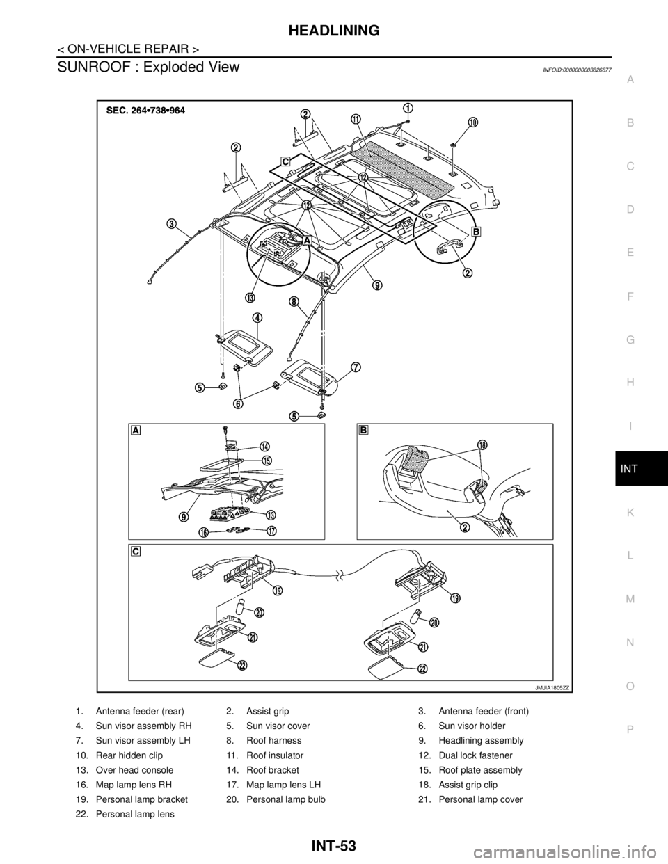
SUNROOF : Exploded ViewINFOID:0000000003826877
1. Antenna feeder (rear) 2. Assist grip 3. Antenna feeder (front)
4. Sun visor assembly RH 5. Sun visor cover 6. Sun visor holder
7. Sun visor assembly LH 8. Roof harness 9. Headlining assembly
10. Rear hidden clip 11. Roof insulator 12. Dual lock fastener
13. Over head console 14. Roof bracket 15. Roof plate assembly
16. Map lamp lens RH 17. Map lamp lens LH 18. Assist grip clip
19. Personal lamp bracket 20. Personal lamp bulb 21. Personal lamp cover
22. Personal lamp lens
JMJIA1805ZZ
Page 3031 of 5121
INT-54
< ON-VEHICLE REPAIR >
HEADLINING
SUNROOF : Removal and Installation
INFOID:0000000003826878
REMOVAL
1. Remove front body side welt (LH/RH) and front pillar garnish (LH/RH). Refer to INT-39, "Removal and
Installation".
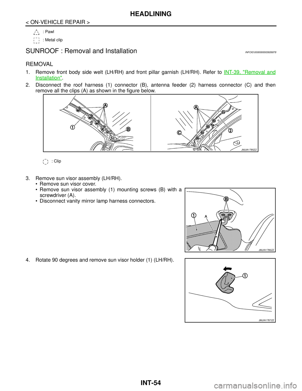
2. Disconnect the roof harness (1) connector (B), antenna feeder (2) harness connector (C) and then
remove all the clips (A) as shown in the figure below.
3. Remove sun visor assembly (LH/RH).
Remove sun visor cover.
Remove sun visor assembly (1) mounting screws (B) with a
screwdriver (A).
Disconnect vanity mirror lamp harness connectors.
4. Rotate 90 degrees and remove sun visor holder (1) (LH/RH).
: Pawl
: Metal clip
: Clip
JMJIA1785ZZ
JMJIA1786ZZ
JMJIA1787ZZ
Page 3044 of 5121

IP-4
< SYMPTOM DIAGNOSIS >
SQUEAK AND RATTLE TROUBLE DIAGNOSES
Confirm that the cause of a noise is repaired by test driving the vehicle. Operate the vehicle under the same
conditions as when the noise originally occurred. Refer to the notes on the Diagnostic Worksheet.
Inspection ProcedureINFOID:0000000003939974
Refer to Table of Contents for specific component removal and installation information.
INSTRUMENT PANEL
Most incidents are caused by contact and movement between:
1. Cluster lid A and instrument panel
2. Acrylic lens and combination meter housing
3. Instrument panel to front pillar garnish
4. Instrument panel to windshield
5. Instrument panel mounting pins
6. Wiring harnesses behind the combination meter
7. A/C defroster duct and duct joint
These incidents can usually be located by tapping or moving the components to duplicate the noise or by
pressing on the components while driving to stop the noise. Most of these incidents can be repaired by apply-
ing felt cloth tape or silicon spray (in hard to reach areas). Urethane pads can be used to insulate wiring har-
ness.
CAUTION:
Never use silicone spray to isolate a squeak or rattle. If the area is saturated with silicone, the recheck
of repair becomes impossible.
CENTER CONSOLE
Components to pay attention to include:
1. Shifter assembly cover to finisher
2. A/C control unit and cluster lid C
3. Wiring harnesses behind audio and A/C control unit
The instrument panel repair and isolation procedures also apply to the center console.
DOORS
Pay attention to the following:
1. Finisher and inner panel making a slapping noise
2. Inside handle escutcheon to door finisher
3. Wiring harnesses tapping
4. Door striker out of alignment causing a popping noise on starts and stops
Tapping or moving the components or pressing on them while driving to duplicate the conditions can isolate
many of these incidents. The areas can usually be insulated with felt cloth tape or insulator foam blocks to
repair the noise.
TRUNK
Trunk noises are often caused by a loose jack or loose items put into the trunk by the customer.
In addition look for the following:
1. Trunk lid dumpers out of adjustment
2. Trunk lid striker out of adjustment
3. Trunk lid torsion bars knocking together
4. A loose license plate or bracket
Most of these incidents can be repaired by adjusting, securing or insulating the item(s) or component(s) caus-
ing the noise.
SUNROOF/HEADLINING
Noises in the sunroof/headlining area can often be traced to one of the following:
1. Sunroof lid, rail, linkage or seals making a rattle or light knocking noise
2. Sunvisor shaft shaking in the holder
3. Front or rear windshield touching headlining and squeaking
Page 3230 of 5121
MA-42
< ON-VEHICLE MAINTENANCE >
BODY MAINTENANCE
BODY MAINTENANCE
LOCKS, HINGES AND HOOD LATCH
LOCKS, HINGES AND HOOD LATCH : LubricatingINFOID:0000000003858318
For hood and hood lock illustration.
Hood: Refer to DLK-191, "
HOOD ASSEMBLY : Exploded View".
Hood lock control: Refer to DLK-220, "
Exploded View".
For door and door lock illustration.
Front door: Refer to DLK-201, "
DOOR ASSEMBLY : Exploded View".
Front door lock: Refer to DLK-222, "
DOOR LOCK : Exploded View".
Rear door: Refer to DLK-207, "
DOOR ASSEMBLY : Exploded View".
Rear door lock: Refer to DLK-227, "
DOOR LOCK : Exploded View".
For trunk lid and trunk lid lock illustration.
Trunk lid: Refer to DLK-213, "
TRUNK LID ASSEMBLY : Exploded View".
Trunk lid lock: Refer to DLK-231, "
Exploded View".
SEAT BELT, BUCKLES, RETRACTORS, ANCHORS AND ADJUSTERS
SEAT BELT, BUCKLES, RETRACTORS, ANCHORS AND ADJUSTERS : Inspection
INFOID:0000000003858319
For front seat belt illustration. Refer to SB-5, "SEAT BELT RETRACTOR : Exploded View".
For rear seat belt illustration. Refer to SB-10, "
SEAT BELT RETRACTOR : Exploded View".
CAUTION:
After any collision, inspect all seat belt assemblies, including retractors and other attached hard-
wares (I.e. anchor bolt, guide rail set). Nissan recommends to replace all seat belt assemblies in use
during a collision, unless not damaged and properly operating after minor collision.
Also inspect seat belt assemblies not in use during a collision, and replace if damaged or improperly
operating.
Seat belt pre-tensioner should be replaced even if the seat belts are not in use during a frontal colli-
sion where the driver and passenger air bags are deployed.
If any component of seat belt assembly is questionable, do not repair.
Replace as seat belt assembly.
If webbing is cut, frayed, or damaged, replace belt assembly.
Never oil tongue and buckle.
Use a genuine NISSAN seat belt assembly.
For details, refer to SB-3, "
SEAT BELT RETRACTOR : Inspection" , SB-8, "SEAT BELT RETRACTOR :
Inspection" in SB section.
Check anchors for loose mounting
Check belts for damage
Check retractor for smooth operation
Check function of buckles and tongues when buckled and released
BODY CORROSION
BODY CORROSION : Checking Body CorrosionINFOID:0000000003858320
Visually check body panels for collision damage (scratches, chipping, rubbing, etc.) or damage to the anti-cor-
rosion materials. In particular, check the following locations.
HEMMED PANELS
Hood front end, door lower end, trunk lid rear end, etc.
PA N E L J O I N T
Side sill of rear fender and center pillar, rear wheel housing of rear fender, around strut tower in engine com-
partment, etc.
PA N E L E D G E
Trunk lid opening, sunroof opening, fender wheel-arch flange, fuel filler lid flange, around holes in panel, etc.
PARTS CONTACT
Waist moulding, windshield moulding, bumper, etc.
Page 3241 of 5121

MIR-8
< SYMPTOM DIAGNOSIS >
SQUEAK AND RATTLE TROUBLE DIAGNOSES
Confirm that the cause of a noise is repaired by test driving the vehicle. Operate the vehicle under the same
conditions as when the noise originally occurred. Refer to the notes on the Diagnostic Worksheet.
Inspection ProcedureINFOID:0000000003941383
Refer to Table of Contents for specific component removal and installation information.
INSTRUMENT PANEL
Most incidents are caused by contact and movement between:
1. Cluster lid A and instrument panel
2. Acrylic lens and combination meter housing
3. Instrument panel to front pillar garnish
4. Instrument panel to windshield
5. Instrument panel mounting pins
6. Wiring harnesses behind the combination meter
7. A/C defroster duct and duct joint
These incidents can usually be located by tapping or moving the components to duplicate the noise or by
pressing on the components while driving to stop the noise. Most of these incidents can be repaired by apply-
ing felt cloth tape or silicon spray (in hard to reach areas). Urethane pads can be used to insulate wiring har-
ness.
CAUTION:
Never use silicone spray to isolate a squeak or rattle. If the area is saturated with silicone, the recheck
of repair becomes impossible.
CENTER CONSOLE
Components to pay attention to include:
1. Shifter assembly cover to finisher
2. A/C control unit and cluster lid C
3. Wiring harnesses behind audio and A/C control unit
The instrument panel repair and isolation procedures also apply to the center console.
DOORS
Pay attention to the following:
1. Finisher and inner panel making a slapping noise
2. Inside handle escutcheon to door finisher
3. Wiring harnesses tapping
4. Door striker out of alignment causing a popping noise on starts and stops
Tapping or moving the components or pressing on them while driving to duplicate the conditions can isolate
many of these incidents. The areas can usually be insulated with felt cloth tape or insulator foam blocks to
repair the noise.
TRUNK
Trunk noises are often caused by a loose jack or loose items put into the trunk by the customer.
In addition look for the following:
1. Trunk lid dumpers out of adjustment
2. Trunk lid striker out of adjustment
3. Trunk lid torsion bars knocking together
4. A loose license plate or bracket
Most of these incidents can be repaired by adjusting, securing or insulating the item(s) or component(s) caus-
ing the noise.
SUNROOF/HEADLINING
Noises in the sunroof/headlining area can often be traced to one of the following:
1. Sunroof lid, rail, linkage or seals making a rattle or light knocking noise
2. Sunvisor shaft shaking in the holder
3. Front or rear windshield touching headlining and squeaking
Page 3732 of 5121

RF-1
BODY EXTERIOR, DOORS, ROOF & VEHICLE SECURITY
C
D
E
F
G
H
I
J
L
M
SECTION RF
A
B
RF
N
O
P
CONTENTS
ROOF
BASIC INSPECTION ....................................3
DIAGNOSIS AND REPAIR WORKFLOW ..........3
WorkFlow ..................................................................3
INSPECTION AND ADJUSTMENT .....................4
ADDITIONAL SERVICE WHEN REPLACING
CONTROL UNIT ..........................................................
4
ADDITIONAL SERVICE WHEN REPLACING
CONTROL UNIT : Description ..................................
4
ADDITIONAL SERVICE WHEN REPLACING
CONTROL UNIT : Special Repair Requirement .......
4
FUNCTION DIAGNOSIS ...............................5
SUNROOF SYSTEM ...........................................5
System Diagram .......................................................5
System Description ...................................................5
Component Parts Location ......................................8
Component Description ............................................8
DIAGNOSIS SYSTEM (BCM) .............................9
COMMON ITEM ...........................................................9
COMMON ITEM : CONSULT-III Function (BCM -
COMMON ITEM) .......................................................
9
RETAINED PWR .......................................................10
RETAINED PWR : CONSULT-III Function (BCM -
RETAINED PWR) ...................................................
10
COMPONENT DIAGNOSIS .........................11
POWER SUPPLY AND GROUND CIRCUIT ......11
BCM ...........................................................................11
BCM : Diagnosis Procedure ....................................11
SUNROOF MOTOR ASSEMBLY ..............................11
SUNROOF MOTOR ASSEMBLY :
Diagnosis Procedure ..............................................
11
SUNSHADE MOTOR ASSEMBLY ............................12
SUNSHADE MOTOR ASSEMBLY :
Diagnosis Procedure ..............................................
12
COMMUNICATION SIGNAL CIRCUIT .............14
Description ...............................................................14
Diagnosis Procedure ...............................................14
SUNROOF SWITCH ..........................................15
Description ...............................................................15
Component Function Check ....................................15
Diagnosis Procedure ..............................................15
Component Inspection .............................................16
DOOR SWITCH .................................................18
Description ...............................................................18
Component Function Check ..................................18
Diagnosis Procedure ...............................................18
Component Inspection .............................................19
ECU DIAGNOSIS .........................................20
BCM (BODY CONTROL MODULE) .................20
Reference Value ......................................................20
Wiring Diagram - BCM - ..........................................43
Fail-safe ...................................................................49
DTC Inspection Priority Chart ...............................51
DTC Index ...............................................................52
SUNROOF MOTOR ASSEMBLY .....................54
Reference Value ......................................................54
Wiring Diagram - SUNROOF CONTROL SYS-
TEM - .......................................................................
56
SUNSHADE MOTOR ASSEMBLY ...................60
Reference Value ......................................................60
Wiring Diagram - SUNROOF CONTROL SYS-
TEM - .......................................................................
61
SYMPTOM DIAGNOSIS ..............................65
SUNROOF DOES NOT OPERATE PROPER-
LY ......................................................................
65
Page 3733 of 5121

RF-2
SUNROOF DOES NOT OPEN ..................................65
SUNROOF DOES NOT OPEN : Description ..........65
SUNROOF DOES NOT OPEN : Diagnosis Proce-
dure ........................................................................
65
SUNROOF DOES NOT CLOSE ................................65
SUNROOF DOES NOT CLOSE : Description ........65
SUNROOF DOES NOT CLOSE : Diagnosis Pro-
cedure .....................................................................
65
SUNROOF DOES NOT TILT UP OR DOWN ............66
SUNROOF DOES NOT TILT UP OR DOWN : De-
scription ..................................................................
66
SUNROOF DOES NOT TILT UP OR DOWN : Di-
agnosis Procedure ..................................................
66
SUNSHADE DOES NOT OPERATE PROP-
ERLY ..................................................................
67
Diagnosis Procedure ..............................................67
AUTO OPERATION DOES NOT OPERATE .....68
Diagnosis Procedure ..............................................68
RETAINED POWER OPERATION DOES NOT
OPERATE PROPERLY .....................................
69
Diagnosis Procedure ..............................................69
ANTI-PINCH FUNCTION DOES NOT OPER-
ATE ....................................................................
70
Diagnosis Procedure ..............................................70
SQUEAK AND RATTLE TROUBLE DIAG-
NOSES ...............................................................
71
Work Flow ...............................................................71
Inspection Procedure ..............................................73
Diagnostic Worksheet .............................................75
PRECAUTION .............................................77
PRECAUTIONS .................................................77
Precaution for Supplemental Restraint System
(SRS) "AIR BAG" and "SEAT BELT PRE-TEN-
SIONER" .................................................................
77
Service Notice ........................................................77
Precaution for Work ................................................77
PREPARATION ..........................................78
PREPARATION .................................................78
Commercial Service Tool ........................................78
ON-VEHICLE REPAIR ...............................79
GLASS LID ........................................................79
Exploded View ........................................................79
Removal and Installation .........................................80
Adjustment ..............................................................81
SUNROOF MOTOR ASSEMBLY ......................82
Exploded View ........................................................82
Removal and Installation .........................................83
SUNSHADE MOTOR ASSEMBLY ....................84
Exploded View ........................................................84
Removal and Installation .........................................85
SUNROOF UNIT ASSEMBLY ...........................86
Exploded View ........................................................86
Removal and Installation .........................................88
Disassembly and Assembly ....................................90
FRONT SUNROOF GLASS ..............................91
Exploded View ........................................................91
Removal and Installation .........................................91
REAR SUNROOF GLASS .................................94
Exploded View ........................................................94
Removal and Installation .........................................94
WIND DEFLECTOR ...........................................97
Exploded View ........................................................97
Removal and Installation .........................................97
SUNSHADE .......................................................99
Exploded View ........................................................99
Removal and Installation .........................................99
SUNROOF SWITCH .........................................101
Exploded View ......................................................101
Removal and Installation .......................................101