Page 3812 of 5121
GLASS LID
RF-81
< ON-VEHICLE REPAIR >
C
D
E
F
G
H
I
J
L
MA
B
RF
N
O
P
5. Remove the glass lid from the vehicle.
INSTALLATION
Install in the reverse order of removal.
CAUTION:
After installing the glass lid, perform the leak test and check that there is no malfunction.
NOTE:
After installation, carry out fitting adjustment. Refer to RF-81, "
Adjustment".
AdjustmentINFOID:0000000003812886
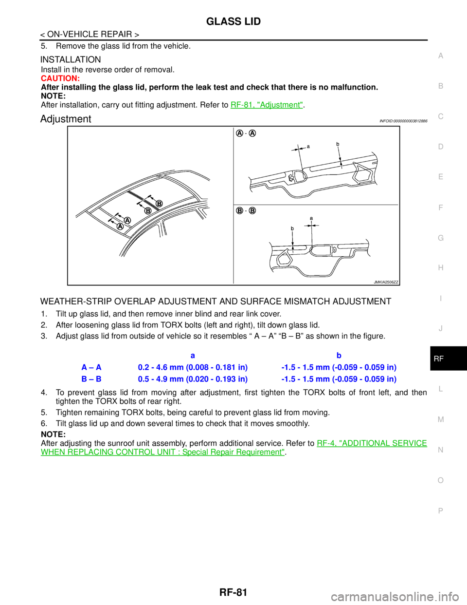
WEATHER-STRIP OVERLAP ADJUSTMENT AND SURFACE MISMATCH ADJUSTMENT
1. Tilt up glass lid, and then remove inner blind and rear link cover.
2. After loosening glass lid from TORX bolts (left and right), tilt down glass lid.
3. Adjust glass lid from outside of vehicle so it resembles “ A – A” “B – B” as shown in the figure.
4. To prevent glass lid from moving after adjustment, first tighten the TORX bolts of front left, and then
tighten the TORX bolts of rear right.
5. Tighten remaining TORX bolts, being careful to prevent glass lid from moving.
6. Tilt glass lid up and down several times to check that it moves smoothly.
NOTE:
After adjusting the sunroof unit assembly, perform additional service. Refer to RF-4, "
ADDITIONAL SERVICE
WHEN REPLACING CONTROL UNIT : Special Repair Requirement".
JMKIA2506ZZ
ab
A – A 0.2 - 4.6 mm (0.008 - 0.181 in) -1.5 - 1.5 mm (-0.059 - 0.059 in)
B – B 0.5 - 4.9 mm (0.020 - 0.193 in) -1.5 - 1.5 mm (-0.059 - 0.059 in)
Page 3813 of 5121
RF-82
< ON-VEHICLE REPAIR >
SUNROOF MOTOR ASSEMBLY
SUNROOF MOTOR ASSEMBLY
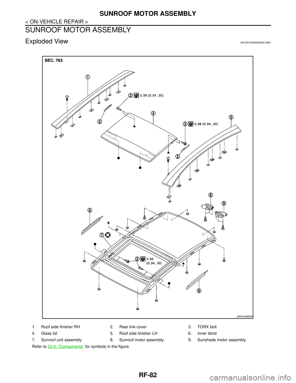
Exploded ViewINFOID:0000000003812887
1. Roof side finisher RH 2. Rear link cover 3. TORX bolt
4. Glass lid 5. Roof side finisher LH 6. Inner blind
7. Sunroof unit assembly 8. Sunroof motor assembly 9. Sunshade motor assembly
Refer to GI-4, "
Components" for symbols in the figure.
JMKIA2488GB
Page 3814 of 5121
SUNROOF MOTOR ASSEMBLY
RF-83
< ON-VEHICLE REPAIR >
C
D
E
F
G
H
I
J
L
MA
B
RF
N
O
P
Removal and InstallationINFOID:0000000003812888
REMOVAL
CAUTION:
Before removing sunroof motor, check that glass lid is fully closed.
After removing sunroof motor, never attempt to rotate sunroof motor assembly as a single unit.
1. Remove the headlining. Refer to INT-54, "
SUNROOF : Removal and Installation".
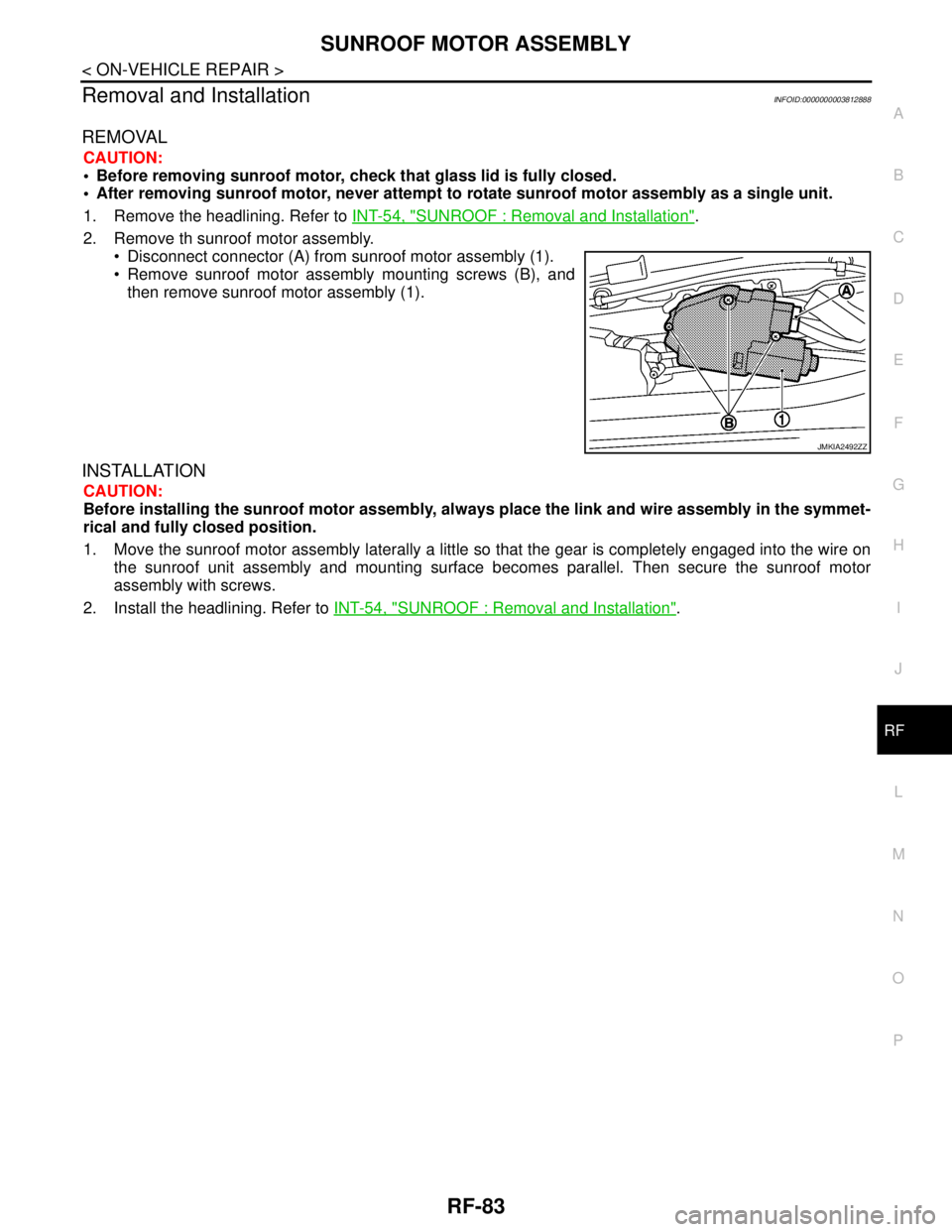
2. Remove th sunroof motor assembly.
Disconnect connector (A) from sunroof motor assembly (1).
Remove sunroof motor assembly mounting screws (B), and
then remove sunroof motor assembly (1).
INSTALLATION
CAUTION:
Before installing the sunroof motor assembly, always place the link and wire assembly in the symmet-
rical and fully closed position.
1. Move the sunroof motor assembly laterally a little so that the gear is completely engaged into the wire on
the sunroof unit assembly and mounting surface becomes parallel. Then secure the sunroof motor
assembly with screws.
2. Install the headlining. Refer to INT-54, "
SUNROOF : Removal and Installation".
JMKIA2492ZZ
Page 3815 of 5121
RF-84
< ON-VEHICLE REPAIR >
SUNSHADE MOTOR ASSEMBLY
SUNSHADE MOTOR ASSEMBLY
Exploded ViewINFOID:0000000003812889
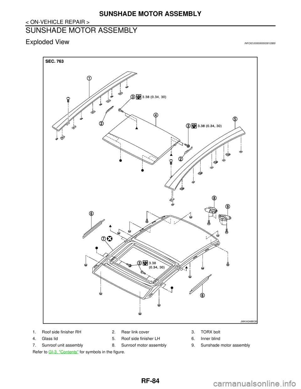
1. Roof side finisher RH 2. Rear link cover 3. TORX bolt
4. Glass lid 5. Roof side finisher LH 6. Inner blind
7. Sunroof unit assembly 8. Sunroof motor assembly 9. Sunshade motor assembly
Refer to GI-3, "
Contents" for symbols in the figure.
JMKIA2488GB
Page 3816 of 5121
SUNSHADE MOTOR ASSEMBLY
RF-85
< ON-VEHICLE REPAIR >
C
D
E
F
G
H
I
J
L
MA
B
RF
N
O
P
Removal and InstallationINFOID:0000000003812890
REMOVAL
CAUTION:
Before removing sunshade motor, check that glass lid is fully closed.
After removing sunshade motor, never attempt to rotate sunshade motor assembly as a single unit.
1. Remove the headlining. Refer to INT-54, "
SUNROOF : Removal and Installation".
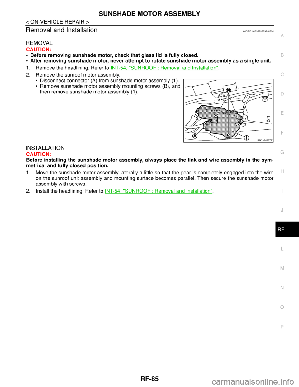
2. Remove the sunroof motor assembly.
Disconnect connector (A) from sunshade motor assembly (1).
Remove sunshade motor assembly mounting screws (B), and
then remove sunshade motor assembly (1).
INSTALLATION
CAUTION:
Before installing the sunshade motor assembly, always place the link and wire assembly in the sym-
metrical and fully closed position.
1. Move the sunshade motor assembly laterally a little so that the gear is completely engaged into the wire
on the sunroof unit assembly and mounting surface becomes parallel. Then secure the sunshade motor
assembly with screws.
2. Install the headlining. Refer to INT-54, "
SUNROOF : Removal and Installation".
JMKIA2493ZZ
Page 3817 of 5121
RF-86
< ON-VEHICLE REPAIR >
SUNROOF UNIT ASSEMBLY
SUNROOF UNIT ASSEMBLY
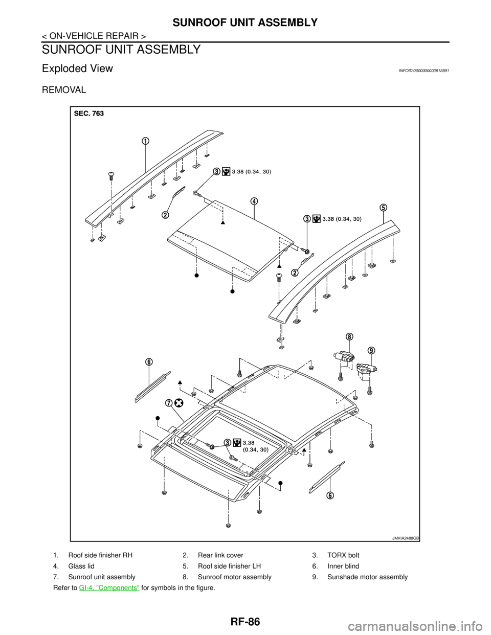
Exploded ViewINFOID:0000000003812891
REMOVAL
1. Roof side finisher RH 2. Rear link cover 3. TORX bolt
4. Glass lid 5. Roof side finisher LH 6. Inner blind
7. Sunroof unit assembly 8. Sunroof motor assembly 9. Sunshade motor assembly
Refer to GI-4, "
Components" for symbols in the figure.
JMKIA2488GB
Page 3818 of 5121
SUNROOF UNIT ASSEMBLY
RF-87
< ON-VEHICLE REPAIR >
C
D
E
F
G
H
I
J
L
MA
B
RF
N
O
P
DISASSEMBLY
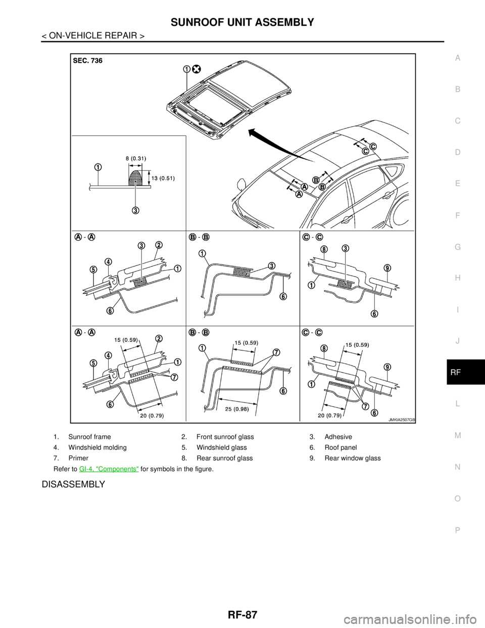
1. Sunroof frame 2. Front sunroof glass 3. Adhesive
4. Windshield molding 5. Windshield glass 6. Roof panel
7. Primer 8. Rear sunroof glass 9. Rear window glass
Refer to GI-4, "
Components" for symbols in the figure.
JMKIA2507GB
Page 3819 of 5121
RF-88
< ON-VEHICLE REPAIR >
SUNROOF UNIT ASSEMBLY
Removal and Installation
INFOID:0000000003812892
REMOVAL
CAUTION:
Always work with a helper.
Never reuse the front and rear sunroof glass which has been removed once.
1. Remove the headlining. Refer to INT-54, "
SUNROOF : Removal and Installation".
2. Remove the glass lid. Refer to RF-80, "
Removal and Installation".
3. Remove the windshield molding. Refer to GW-11, "
Removal and Installation".
4. Paint matching marks on body before removing the sunroof unit assembly.
5. Remove nuts and bolts from the front end, side rail and rear end.
6. Apply protective tape around the roof panel to protect the surface from damage.
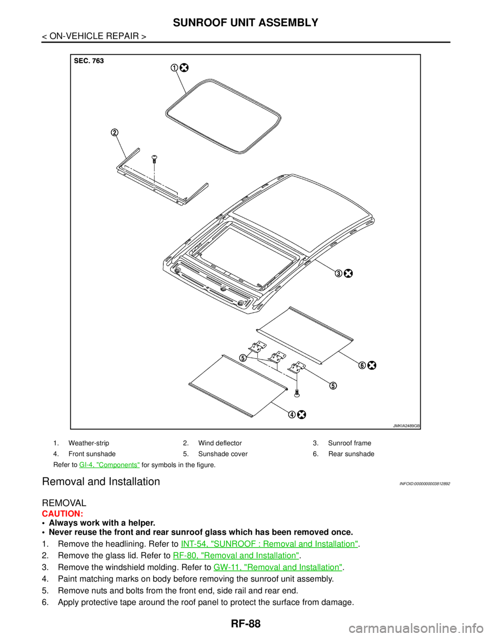
1. Weather-strip 2. Wind deflector 3. Sunroof frame
4. Front sunshade 5. Sunshade cover 6. Rear sunshade
Refer to GI-4, "
Components" for symbols in the figure.
JMKIA2489GB