Page 1108 of 5121
CHG-10
< COMPONENT DIAGNOSIS >
L TERMINAL CIRCUIT (OPEN)
L TERMINAL CIRCUIT (OPEN)
DescriptionINFOID:0000000003860523
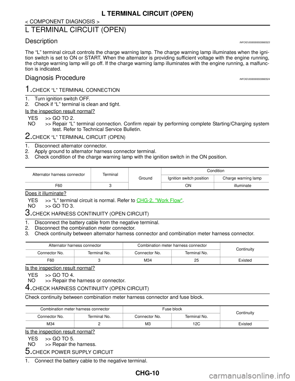
The “L” terminal circuit controls the charge warning lamp. The charge warning lamp illuminates when the igni-
tion switch is set to ON or START. When the alternator is providing sufficient voltage with the engine running,
the charge warning lamp will go off. If the charge warning lamp illuminates with the engine running, a malfunc-
tion is indicated.
Diagnosis ProcedureINFOID:0000000003860524
1.CHECK “L” TERMINAL CONNECTION
1. Turn ignition switch OFF.
2. Check if “L” terminal is clean and tight.
Is the inspection result normal?
YES >> GO TO 2.
NO >> Repair “L” terminal connection. Confirm repair by performing complete Starting/Charging system
test. Refer to Technical Service Bulletin.
2.CHECK “L” TERMINAL CIRCUIT (OPEN)
1. Disconnect alternator connector.
2. Apply ground to alternator harness connector terminal.
3. Check condition of the charge warning lamp with the ignition switch in the ON position.
Does it illuminate?
YES >> “L” terminal circuit is normal. Refer to CHG-2, "Work Flow".
NO >> GO TO 3.
3.CHECK HARNESS CONTINUITY (OPEN CIRCUIT)
1. Disconnect the battery cable from the negative terminal.
2. Disconnect the combination meter connector.
3. Check continuity between alternator harness connector and combination meter harness connector.
Is the inspection result normal?
YES >> GO TO 4.
NO >> Repair the harness or connector.
4.CHECK HARNESS CONTINUITY (OPEN CIRCUIT)
Check continuity between combination meter harness connector and fuse block.
Is the inspection result normal?
YES >> GO TO 5.
NO >> Repair the harness.
5.CHECK POWER SUPPLY CIRCUIT
1. Connect the battery cable to the negative terminal.
Alternator harness connector Terminal
GroundCondition
Ignition switch position Charge warning lamp
F60 3 ON illuminate
Alternator harness connector Combination meter harness connector
Continuity
Connector No. Terminal No. Connector No. Terminal No.
F60 3 M34 25 Existed
Combination meter harness connector Fuse block
Continuity
Connector No. Terminal No. Connector No. Terminal No.
M34 2 M3 12C Existed
Page 1110 of 5121
CHG-12
< COMPONENT DIAGNOSIS >
L TERMINAL CIRCUIT (SHORT)
L TERMINAL CIRCUIT (SHORT)
DescriptionINFOID:0000000003860525
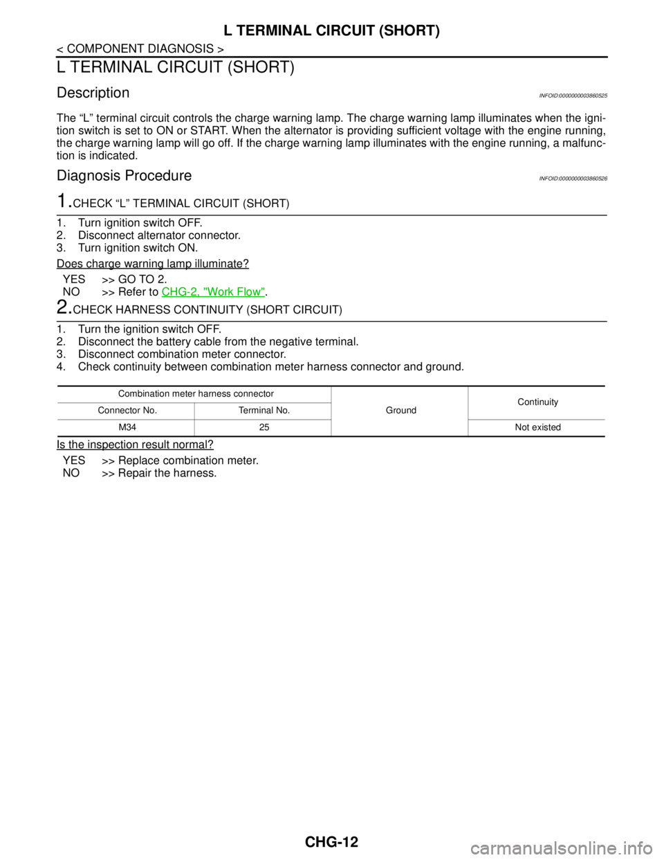
The “L” terminal circuit controls the charge warning lamp. The charge warning lamp illuminates when the igni-
tion switch is set to ON or START. When the alternator is providing sufficient voltage with the engine running,
the charge warning lamp will go off. If the charge warning lamp illuminates with the engine running, a malfunc-
tion is indicated.
Diagnosis ProcedureINFOID:0000000003860526
1.CHECK “L” TERMINAL CIRCUIT (SHORT)
1. Turn ignition switch OFF.
2. Disconnect alternator connector.
3. Turn ignition switch ON.
Does charge warning lamp illuminate?
YES >> GO TO 2.
NO >> Refer to CHG-2, "
Work Flow".
2.CHECK HARNESS CONTINUITY (SHORT CIRCUIT)
1. Turn the ignition switch OFF.
2. Disconnect the battery cable from the negative terminal.
3. Disconnect combination meter connector.
4. Check continuity between combination meter harness connector and ground.
Is the inspection result normal?
YES >> Replace combination meter.
NO >> Repair the harness.
Combination meter harness connector
GroundContinuity
Connector No. Terminal No.
M34 25 Not existed
Page 1111 of 5121
CHG
S TERMINAL CIRCUIT
CHG-13
< COMPONENT DIAGNOSIS >
C
D
E
F
G
H
I
J
K
L B A
O
P N
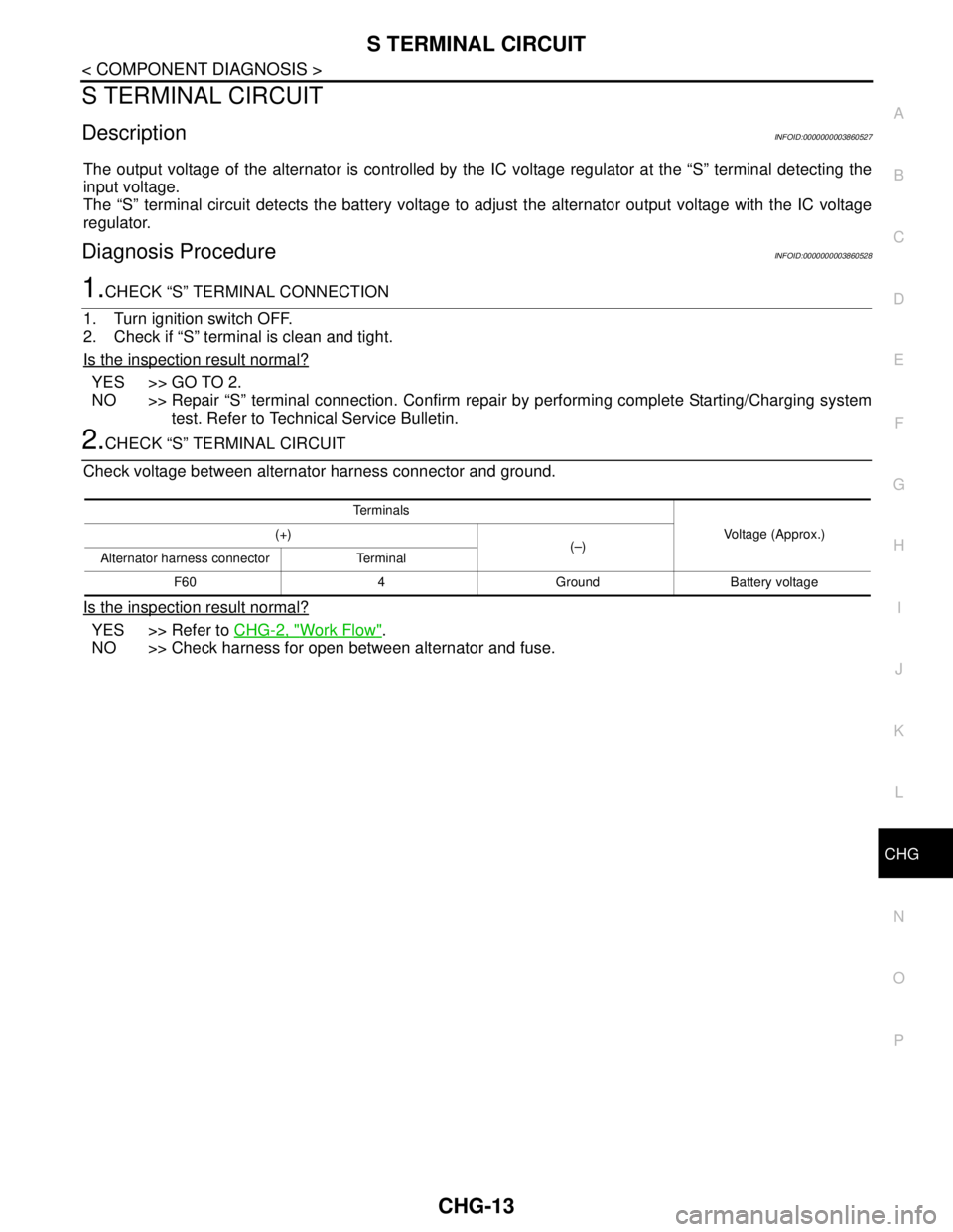
S TERMINAL CIRCUIT
DescriptionINFOID:0000000003860527
The output voltage of the alternator is controlled by the IC voltage regulator at the “S” terminal detecting the
input voltage.
The “S” terminal circuit detects the battery voltage to adjust the alternator output voltage with the IC voltage
regulator.
Diagnosis ProcedureINFOID:0000000003860528
1.CHECK “S” TERMINAL CONNECTION
1. Turn ignition switch OFF.
2. Check if “S” terminal is clean and tight.
Is the inspection result normal?
YES >> GO TO 2.
NO >> Repair “S” terminal connection. Confirm repair by performing complete Starting/Charging system
test. Refer to Technical Service Bulletin.
2.CHECK “S” TERMINAL CIRCUIT
Check voltage between alternator harness connector and ground.
Is the inspection result normal?
YES >> Refer to CHG-2, "Work Flow".
NO >> Check harness for open between alternator and fuse.
Te r m i n a l s
Voltage (Approx.) (+)
(–)
Alternator harness connector Terminal
F60 4 Ground Battery voltage
Page 1117 of 5121
CHG
PREPARATION
CHG-19
< PREPARATION >
C
D
E
F
G
H
I
J
K
L B A
O
P N
PREPARATION
PREPARATION
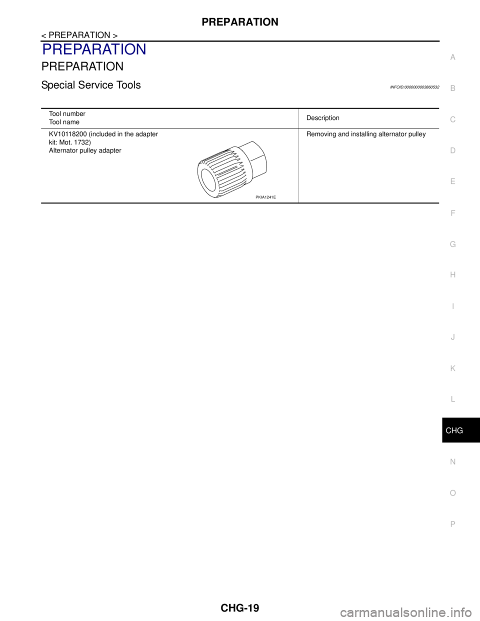
Special Service ToolsINFOID:0000000003860532
Tool number
Tool nameDescription
KV10118200 (included in the adapter
kit: Mot. 1732)
Alternator pulley adapterRemoving and installing alternator pulley
PKIA1241E
Page 1118 of 5121
CHG-20
< ON-VEHICLE MAINTENANCE >
CHARGING SYSTEM PRELIMINARY INSPECTION
ON-VEHICLE MAINTENANCE
CHARGING SYSTEM PRELIMINARY INSPECTION
Inspection ProcedureINFOID:0000000003860533
1.CHECK BATTERY TERMINALS CONNECTION
Check if battery terminals are clean and tight.
Is the inspection result normal?
YES >> GO TO 2.
NO >> Repair battery terminals connection.
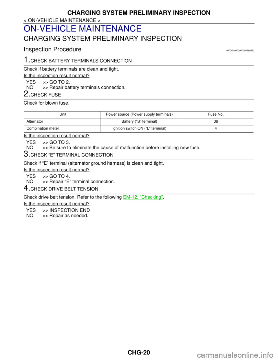
2.CHECK FUSE
Check for blown fuse.
Is the inspection result normal?
YES >> GO TO 3.
NO >> Be sure to eliminate the cause of malfunction before installing new fuse.
3.CHECK “E” TERMINAL CONNECTION
Check if “E” terminal (alternator ground harness) is clean and tight.
Is the inspection result normal?
YES >> GO TO 4.
NO >> Repair “E” terminal connection.
4.CHECK DRIVE BELT TENSION
Check drive belt tension. Refer to the following EM-12, "
Checking".
Is the inspection result normal?
YES >> INSPECTION END
NO >> Repair as needed.
Unit Power source (Power supply terminals) Fuse No.
Alternator Battery (“S” terminal) 36
Combination meter Ignition switch ON (“L” terminal) 4
Page 1119 of 5121
CHG
ALTERNATOR
CHG-21
< ON-VEHICLE REPAIR >
C
D
E
F
G
H
I
J
K
L B A
O
P N
ON-VEHICLE REPAIR
ALTERNATOR
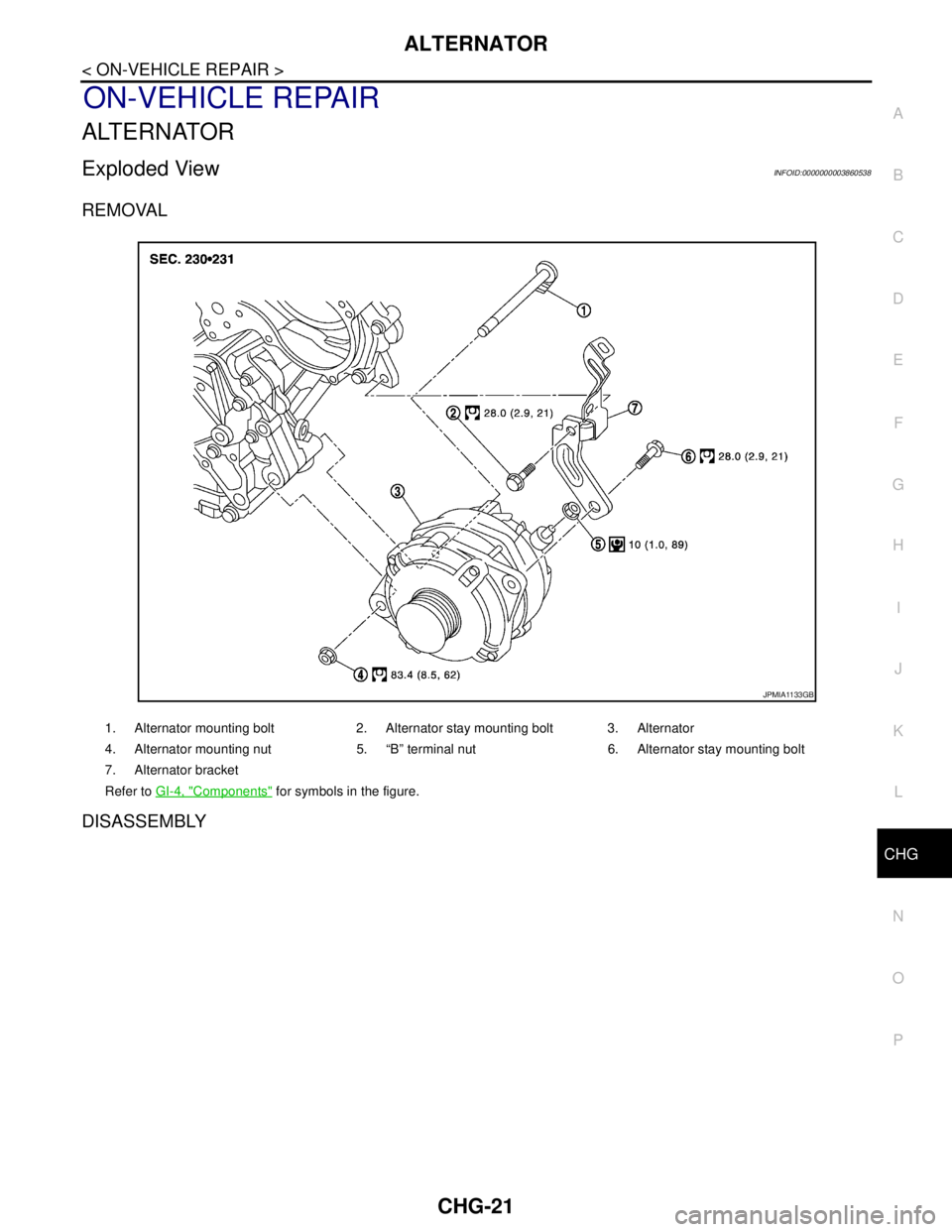
Exploded ViewINFOID:0000000003860538
REMOVAL
DISASSEMBLY
1. Alternator mounting bolt 2. Alternator stay mounting bolt 3. Alternator
4. Alternator mounting nut 5. “B” terminal nut 6. Alternator stay mounting bolt
7. Alternator bracket
Refer to GI-4, "
Components" for symbols in the figure.
JPMIA1133GB
Page 1120 of 5121
CHG-22
< ON-VEHICLE REPAIR >
ALTERNATOR
Type: A003TJ1791
Removal and InstallationINFOID:0000000003860539
REMOVAL
1. Disconnect the negative battery terminal.
2. Remove engine cover.
3. Remove front wheel and tire (RH).
4. Remove splash guard (RH) Refer to EXT-22, "
FENDER PROTECTOR : Exploded View".
5. Remove air cleaner and air duct assembly. Refer to EM-26, "
Removal and Installation".
6. Remove drive belt. Refer to EM-25, "
Removal and Installation".
7. Remove A/C compressor. Refer to HA-36, "
Removal and Installation".
8. Remove idler pulley.
9. Disconnect the oil pressure switch.
10. Disconnect the alternator harness connectors.
11. Remove the alternator bolt and nuts.
12. Slide the alternator out and remove.
INSTALLATION
Installation is in the reverse order of removal.
CAUTION:
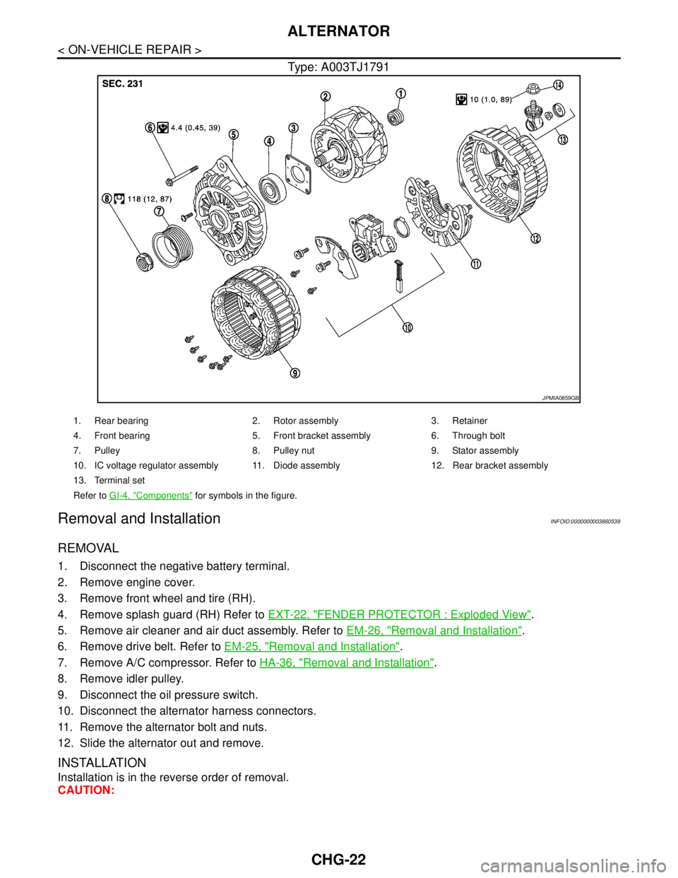
JPMIA0859GB
1. Rear bearing 2. Rotor assembly 3. Retainer
4. Front bearing 5. Front bracket assembly 6. Through bolt
7. Pulley 8. Pulley nut 9. Stator assembly
10. IC voltage regulator assembly 11. Diode assembly 12. Rear bracket assembly
13. Terminal set
Refer to GI-4, "
Components" for symbols in the figure.
Page 1121 of 5121
CHG
ALTERNATOR
CHG-23
< ON-VEHICLE REPAIR >
C
D
E
F
G
H
I
J
K
L B A
O
P N
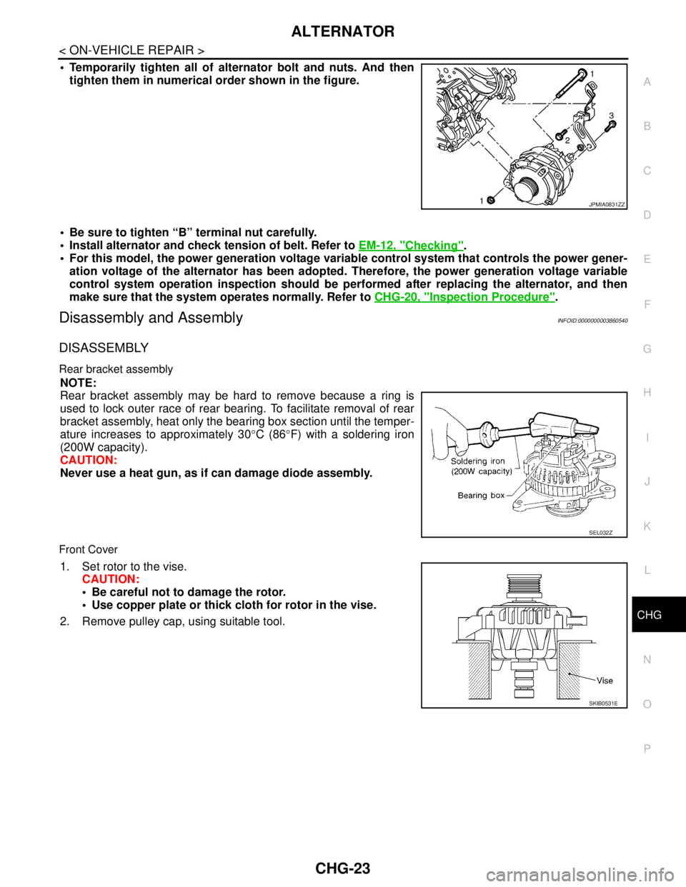
Temporarily tighten all of alternator bolt and nuts. And then
tighten them in numerical order shown in the figure.
Be sure to tighten “B” terminal nut carefully.
Install alternator and check tension of belt. Refer to EM-12, "
Checking".
For this model, the power generation voltage variable control system that controls the power gener-
ation voltage of the alternator has been adopted. Therefore, the power generation voltage variable
control system operation inspection should be performed after replacing the alternator, and then
make sure that the system operates normally. Refer to CHG-20, "
Inspection Procedure".
Disassembly and AssemblyINFOID:0000000003860540
DISASSEMBLY
Rear bracket assembly
NOTE:
Rear bracket assembly may be hard to remove because a ring is
used to lock outer race of rear bearing. To facilitate removal of rear
bracket assembly, heat only the bearing box section until the temper-
ature increases to approximately 30°C (86°F) with a soldering iron
(200W capacity).
CAUTION:
Never use a heat gun, as if can damage diode assembly.
Front Cover
1. Set rotor to the vise.
CAUTION:
Be careful not to damage the rotor.
Use copper plate or thick cloth for rotor in the vise.
2. Remove pulley cap, using suitable tool.
JPMIA0831ZZ
SEL032Z
SKIB0531E