2008 NISSAN TEANA alternator
[x] Cancel search: alternatorPage 2183 of 5121
![NISSAN TEANA 2008 Service Manual EXL-154
< ECU DIAGNOSIS >[XENON TYPE]
IPDM E/R (INTELLIGENT POWER DISTRIBUTION MODULE ENGINE ROOM)
If No CAN Communication Is Available With BCM
IGNITION RELAY MALFUNCTION DETECTION FUNCTION
IPDM E/](/manual-img/5/57391/w960_57391-2182.png "NISSAN TEANA 2008 Service Manual EXL-154
< ECU DIAGNOSIS >[XENON TYPE]
IPDM E/R (INTELLIGENT POWER DISTRIBUTION MODULE ENGINE ROOM)
If No CAN Communication Is Available With BCM
IGNITION RELAY MALFUNCTION DETECTION FUNCTION
IPDM E/")
EXL-154
< ECU DIAGNOSIS >[XENON TYPE]
IPDM E/R (INTELLIGENT POWER DISTRIBUTION MODULE ENGINE ROOM)
If No CAN Communication Is Available With BCM
IGNITION RELAY MALFUNCTION DETECTION FUNCTION
IPDM E/R monitors the voltage at the contact circuit and excitation coil circuit of the ignition relay inside it.
IPDM E/R judges the ignition relay error if the voltage differs between the contact circuit and the excitation
coil circuit.
If the ignition relay cannot turn OFF due to contact seizure, it activates the tail lamp relay for 10 minutes to
alert the user to the ignition relay malfunction when the ignition switch is turned OFF.
FRONT WIPER CONTROL
IPDM E/R detects front wiper stop position by a front wiper auto stop signal.
When a front wiper auto stop signal is in the conditions listed below, IPDM E/R stops power supply to wiper
after repeating a front wiper 10 seconds activation and 20 seconds stop five times.
Control part Fail-safe operation
Cooling fan Turns ON the cooling fan relay-2 and the cooling fan relay-3 when ignition switch is
turned ON (Cooling fan operates at HI)
Turns OFF the cooling fan relay-1, the cooling fan relay-2 and the cooling fan relay-3
when the ignition switch is turned OFF (Cooling fan does not operate)
A/C compressor A/C relay OFF
Alternator Outputs the power generation command signal (PWM signal) 0%
Control part Fail-safe operation
Headlamp Turns ON the headlamp low relay when the ignition switch is turned ON
Turns OFF the headlamp low relay when the ignition switch is turned OFF
Headlamp high relay OFF
Parking lamps
License plate lamps
Illuminations
Tail lamps Turns ON the tail lamp relay when the ignition switch is turned ON
Turns OFF the tail lamp relay when the ignition switch is turned OFF
Front wiper The status just before activation of fail-safe control is maintained until the ignition
switch is turned OFF while the front wiper is operating at LO or HI speed.
The wiper is operated at LO speed until the ignition switch is turned OFF if the fail-
safe control is activated while the front wiper is set in the INT mode and the front wiper
motor is operating.
Front fog lamps Front fog lamp relay OFF
Horn Horn OFF
Ignition relay The status just before activation of fail-safe is maintained.
Starter motor Starter control relay OFF
Steering lock unit Steering lock relay OFF
Headlamp washer relay Headlamp washer relay OFF
Voltage judgment
IPDM E/R judgment Operation
Ignition relay contact sideIgnition relay excitation coil
side
ON ON Ignition relay ON normal —
OFF OFF Ignition relay OFF normal —
ON OFF Ignition relay ON stuck Detects DTC “B2098: IGN RELAY ON”
Turns ON the tail lamp relay for 10 min-
utes
OFF ON Ignition relay OFF stuck Detects DTC “B2099: IGN RELAY OFF”
Page 2355 of 5121
![NISSAN TEANA 2008 Service Manual EXL-326
< ECU DIAGNOSIS >[HALOGEN TYPE]
IPDM E/R (INTELLIGENT POWER DISTRIBUTION MODULE ENGINE ROOM)
If No CAN Communication Is Available With BCM
IGNITION RELAY MALFUNCTION DETECTION FUNCTION
IPDM](/manual-img/5/57391/w960_57391-2354.png "NISSAN TEANA 2008 Service Manual EXL-326
< ECU DIAGNOSIS >[HALOGEN TYPE]
IPDM E/R (INTELLIGENT POWER DISTRIBUTION MODULE ENGINE ROOM)
If No CAN Communication Is Available With BCM
IGNITION RELAY MALFUNCTION DETECTION FUNCTION
IPDM")
EXL-326
< ECU DIAGNOSIS >[HALOGEN TYPE]
IPDM E/R (INTELLIGENT POWER DISTRIBUTION MODULE ENGINE ROOM)
If No CAN Communication Is Available With BCM
IGNITION RELAY MALFUNCTION DETECTION FUNCTION
IPDM E/R monitors the voltage at the contact circuit and excitation coil circuit of the ignition relay inside it.
IPDM E/R judges the ignition relay error if the voltage differs between the contact circuit and the excitation
coil circuit.
If the ignition relay cannot turn OFF due to contact seizure, it activates the tail lamp relay for 10 minutes to
alert the user to the ignition relay malfunction when the ignition switch is turned OFF.
FRONT WIPER CONTROL
IPDM E/R detects front wiper stop position by a front wiper auto stop signal.
When a front wiper auto stop signal is in the conditions listed below, IPDM E/R stops power supply to wiper
after repeating a front wiper 10 seconds activation and 20 seconds stop five times.
Control part Fail-safe operation
Cooling fan Turns ON the cooling fan relay-2 and the cooling fan relay-3 when ignition switch is
turned ON (Cooling fan operates at HI)
Turns OFF the cooling fan relay-1, the cooling fan relay-2 and the cooling fan relay-3
when the ignition switch is turned OFF (Cooling fan does not operate)
A/C compressor A/C relay OFF
Alternator Outputs the power generation command signal (PWM signal) 0%
Control part Fail-safe operation
Headlamp Turns ON the headlamp low relay when the ignition switch is turned ON
Turns OFF the headlamp low relay when the ignition switch is turned OFF
Headlamp high relay OFF
Parking lamps
License plate lamps
Illuminations
Tail lamps Turns ON the tail lamp relay when the ignition switch is turned ON
Turns OFF the tail lamp relay when the ignition switch is turned OFF
Front wiper The status just before activation of fail-safe control is maintained until the ignition
switch is turned OFF while the front wiper is operating at LO or HI speed.
The wiper is operated at LO speed until the ignition switch is turned OFF if the fail-
safe control is activated while the front wiper is set in the INT mode and the front wiper
motor is operating.
Front fog lamps Front fog lamp relay OFF
Horn Horn OFF
Ignition relay The status just before activation of fail-safe is maintained.
Starter motor Starter control relay OFF
Steering lock unit Steering lock relay OFF
Headlamp washer relay Headlamp washer relay OFF
Voltage judgment
IPDM E/R judgment Operation
Ignition relay contact sideIgnition relay excitation coil
side
ON ON Ignition relay ON normal —
OFF OFF Ignition relay OFF normal —
ON OFF Ignition relay ON stuck Detects DTC “B2098: IGN RELAY ON”
Turns ON the tail lamp relay for 10 min-
utes
OFF ON Ignition relay OFF stuck Detects DTC “B2099: IGN RELAY OFF”
Page 3201 of 5121
ENGINE MAINTENANCE
MA-13
< ON-VEHICLE MAINTENANCE >
C
D
E
F
G
H
I
J
K
L
MB
MAN
OA
ENGINE MAINTENANCE
DRIVE BELT
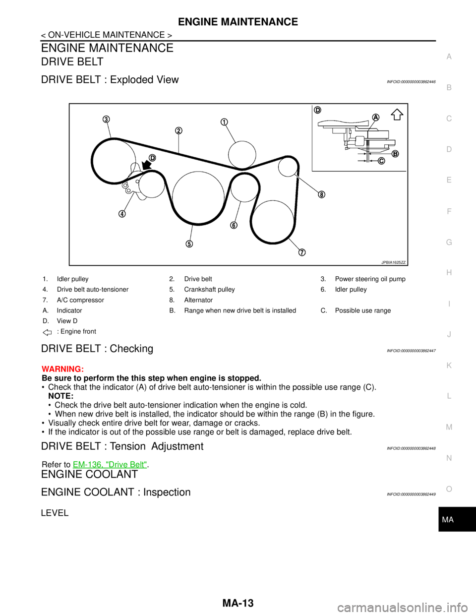
DRIVE BELT : Exploded ViewINFOID:0000000003862446
DRIVE BELT : CheckingINFOID:0000000003862447
WARNING:
Be sure to perform the this step when engine is stopped.
Check that the indicator (A) of drive belt auto-tensioner is within the possible use range (C).
NOTE:
Check the drive belt auto-tensioner indication when the engine is cold.
When new drive belt is installed, the indicator should be within the range (B) in the figure.
Visually check entire drive belt for wear, damage or cracks.
If the indicator is out of the possible use range or belt is damaged, replace drive belt.
DRIVE BELT : Tension AdjustmentINFOID:0000000003862448
Refer to EM-136, "Drive Belt".
ENGINE COOLANT
ENGINE COOLANT : InspectionINFOID:0000000003862449
LEVEL
JPBIA1625ZZ
1. Idler pulley 2. Drive belt 3. Power steering oil pump
4. Drive belt auto-tensioner 5. Crankshaft pulley 6. Idler pulley
7. A/C compressor 8. Alternator
A. Indicator B. Range when new drive belt is installed C. Possible use range
D. View D
: Engine front
Page 3203 of 5121
ENGINE MAINTENANCE
MA-15
< ON-VEHICLE MAINTENANCE >
C
D
E
F
G
H
I
J
K
L
MB
MAN
OA
If water drain plugs on cylinder block are removed, close and tighten them. Refer to EM-110, "Dis-
assembly and Assembly".
2. Check that each hose clamp has been firmly tightened.
3. Remove air duct assembly and air cleaner cases (upper and lower) assembly. Refer to EM-26, "
Exploded
View".
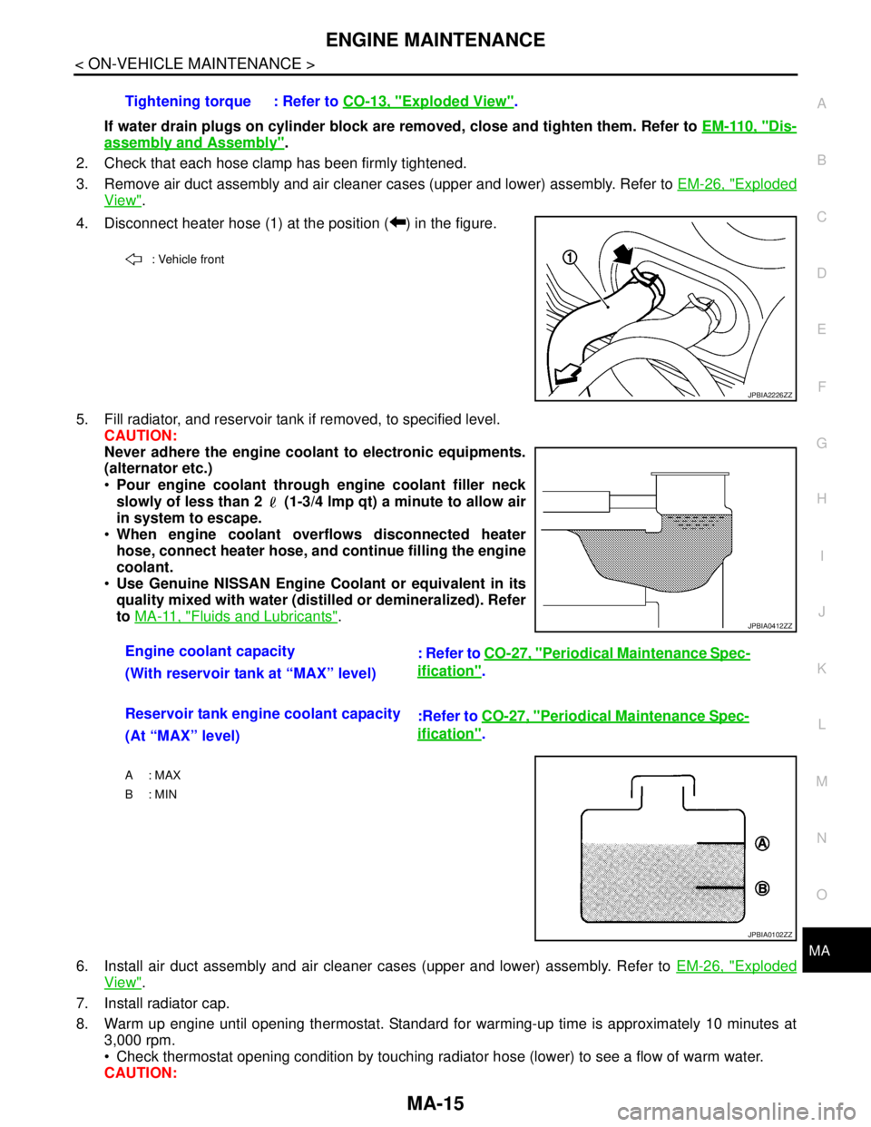
4. Disconnect heater hose (1) at the position ( ) in the figure.
5. Fill radiator, and reservoir tank if removed, to specified level.
CAUTION:
Never adhere the engine coolant to electronic equipments.
(alternator etc.)
Pour engine coolant through engine coolant filler neck
slowly of less than 2 (1-3/4 lmp qt) a minute to allow air
in system to escape.
When engine coolant overflows disconnected heater
hose, connect heater hose, and continue filling the engine
coolant.
Use Genuine NISSAN Engine Coolant or equivalent in its
quality mixed with water (distilled or demineralized). Refer
to MA-11, "
Fluids and Lubricants".
6. Install air duct assembly and air cleaner cases (upper and lower) assembly. Refer to EM-26, "
Exploded
View".
7. Install radiator cap.
8. Warm up engine until opening thermostat. Standard for warming-up time is approximately 10 minutes at
3,000 rpm.
Check thermostat opening condition by touching radiator hose (lower) to see a flow of warm water.
CAUTION:Tightening torque : Refer to CO-13, "
Exploded View".
: Vehicle front
JPBIA2226ZZ
Engine coolant capacity
: Refer to CO-27, "Periodical Maintenance Spec-
ification".
(With reservoir tank at “MAX” level)
Reservoir tank engine coolant capacity
:Refer to CO-27, "
Periodical Maintenance Spec-
ification".
(At “MAX” level)
A : MAX
B: MIN
JPBIA0412ZZ
JPBIA0102ZZ
Page 3204 of 5121
MA-16
< ON-VEHICLE MAINTENANCE >
ENGINE MAINTENANCE
Watch water temperature gauge so as not to overheat engine.
9. Stop the engine and cool down to less than approximately 50°C (122°F).
Cool down using fan to reduce the time.
If necessary, refill radiator up to filler neck with engine coolant.
CAUTION:
Never adhere the engine coolant to electronic equipments. (alternator etc.)
10. Refill reservoir tank to “MAX” level line with engine coolant.
11. Repeat steps 7 through 10 two or more times with radiator cap installed until engine coolant level no
longer drops.
12. Check cooling system for leakage with engine running.
13. Warm up the engine, and check for sound of engine coolant flow while running engine from idle up to
3,000 rpm with heater temperature controller set at several position between “COOL” and “WARM”.
Sound may be noticeable at heater unit.
14. Repeat step 13 three times.
15. If sound is heard, bleed air from cooling system by repeating step 5, and steps from 7 to 14 until engine
coolant level no longer drops.
ENGINE COOLANT : FlushingINFOID:0000000003862452
1. Install reservoir tank if removed, and radiator drain plug.
CAUTION:
Be sure to clean drain plug and install with new O-ring.
If water drain plugs on cylinder block are removed, close and tighten them. Refer to EM-110, "
Dis-
assembly and Assembly".
2. Remove air duct assembly and air cleaner cases (upper and lower) assembly. Refer to EM-26, "
Exploded
View".
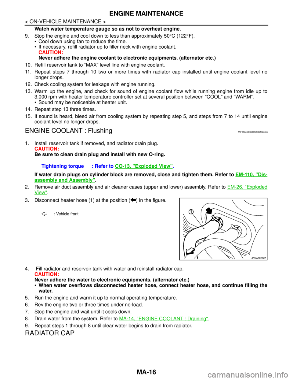
3. Disconnect heater hose (1) at the position ( ) in the figure.
4. Fill radiator and reservoir tank with water and reinstall radiator cap.
CAUTION:
Never adhere the water to electronic equipments. (alternator etc.)
When water overflows disconnected heater hose, connect heater hose, and continue filling the
water.
5. Run the engine and warm it up to normal operating temperature.
6. Rev the engine two or three times under no-load.
7. Stop the engine and wait until it cools down.
8. Drain water from the system. Refer to MA-14, "
ENGINE COOLANT : Draining".
9. Repeat steps 1 through 8 until clear water begins to drain from radiator.
RADIATOR CAP
Tightening torque : Refer to CO-13, "Exploded View".
: Vehicle front
JPBIA2226ZZ
Page 3311 of 5121
MWI
COMBINATION METER
MWI-57
< ECU DIAGNOSIS >
C
D
E
F
G
H
I
J
K
L
MB A
O
P
23
(B)Ground Ground —Ignition
switch
ON—0 V
24
(B/W)GroundFuel level sensor signal
ground—Ignition
switch
ON—0 V
25
(BR)Ground Alternator signal InputIgnition
switch
ONCharge warning lamp ON 2 V
Charge warning lamp OFF 12 V
26
(G/R)Ground Parking brake switch signal InputIgnition
switch
ONWhen parking brake is ap-
plied0 V
When parking brake is re-
leased5 V
27
(V)GroundBrake fluid level switch sig-
nalInputIgnition
switch
ONBrake fluid level is normal 12 V
Brake fluid level is less than
low level0 V
28
(L/O)Ground Security signal InputIgnition
switch
ONSecurity warning lamp OFF 12 V
Security warning lamp ON 0 V
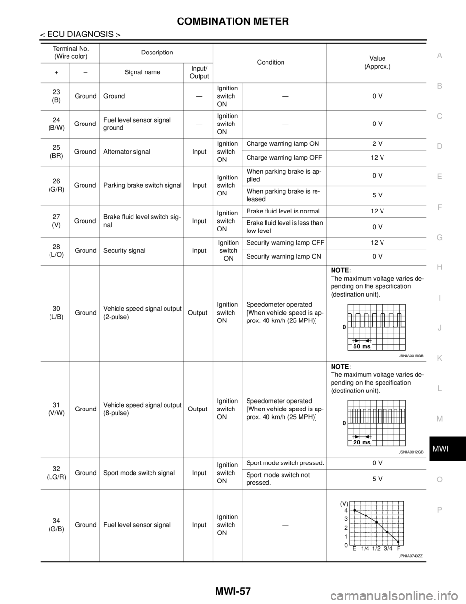
30
(L/B)GroundVehicle speed signal output
(2-pulse)OutputIgnition
switch
ONSpeedometer operated
[When vehicle speed is ap-
prox. 40 km/h (25 MPH)]NOTE:
The maximum voltage varies de-
pending on the specification
(destination unit).
31
(V/W)GroundVehicle speed signal output
(8-pulse)OutputIgnition
switch
ONSpeedometer operated
[When vehicle speed is ap-
prox. 40 km/h (25 MPH)]NOTE:
The maximum voltage varies de-
pending on the specification
(destination unit).
32
(LG/R)Ground Sport mode switch signal InputIgnition
switch
ONSport mode switch pressed. 0 V
Sport mode switch not
pressed.5 V
34
(G/B)Ground Fuel level sensor signal InputIgnition
switch
ON— Te r m i n a l N o .
(Wire color)Description
ConditionVa l u e
(Approx.)
+ – Signal nameInput/
Output
JSNIA0015GB
JSNIA0012GB
JPNIA0740ZZ
Page 3368 of 5121

MWI-114
< ECU DIAGNOSIS >
IPDM E/R (INTELLIGENT POWER DISTRIBUTION MODULE ENGINE ROOM)
If No CAN Communication Is Available With BCM
IGNITION RELAY MALFUNCTION DETECTION FUNCTION
IPDM E/R monitors the voltage at the contact circuit and excitation coil circuit of the ignition relay inside it.
IPDM E/R judges the ignition relay error if the voltage differs between the contact circuit and the excitation
coil circuit.
If the ignition relay cannot turn OFF due to contact seizure, it activates the tail lamp relay for 10 minutes to
alert the user to the ignition relay malfunction when the ignition switch is turned OFF.
FRONT WIPER CONTROL
IPDM E/R detects front wiper stop position by a front wiper auto stop signal.
When a front wiper auto stop signal is in the conditions listed below, IPDM E/R stops power supply to wiper
after repeating a front wiper 10 seconds activation and 20 seconds stop five times.
Control part Fail-safe operation
Cooling fan Turns ON the cooling fan relay-2 and the cooling fan relay-3 when ignition switch is
turned ON (Cooling fan operates at HI)
Turns OFF the cooling fan relay-1, the cooling fan relay-2 and the cooling fan relay-3
when the ignition switch is turned OFF (Cooling fan does not operate)
A/C compressor A/C relay OFF
Alternator Outputs the power generation command signal (PWM signal) 0%
Control part Fail-safe operation
Headlamp Turns ON the headlamp low relay when the ignition switch is turned ON
Turns OFF the headlamp low relay when the ignition switch is turned OFF
Headlamp high relay OFF
Parking lamps
License plate lamps
Illuminations
Tail lamps Turns ON the tail lamp relay when the ignition switch is turned ON
Turns OFF the tail lamp relay when the ignition switch is turned OFF
Front wiper The status just before activation of fail-safe control is maintained until the ignition
switch is turned OFF while the front wiper is operating at LO or HI speed.
The wiper is operated at LO speed until the ignition switch is turned OFF if the fail-
safe control is activated while the front wiper is set in the INT mode and the front wiper
motor is operating.
Front fog lamps Front fog lamp relay OFF
Horn Horn OFF
Ignition relay The status just before activation of fail-safe is maintained.
Starter motor Starter control relay OFF
Steering lock unit Steering lock relay OFF
Headlamp washer relay Headlamp washer relay OFF
Voltage judgment
IPDM E/R judgment Operation
Ignition relay contact sideIgnition relay excitation coil
side
ON ON Ignition relay ON normal —
OFF OFF Ignition relay OFF normal —
ON OFF Ignition relay ON stuck Detects DTC “B2098: IGN RELAY ON”
Turns ON the tail lamp relay for 10 min-
utes
OFF ON Ignition relay OFF stuck Detects DTC “B2099: IGN RELAY OFF”
Page 3398 of 5121
![NISSAN TEANA 2008 Service Manual PCS
POWER CONTROL SYSTEM
PCS-7
< FUNCTION DIAGNOSIS >[IPDM E/R]
C
D
E
F
G
H
I
J
K
L B A
O
P N
POWER CONTROL SYSTEM
System DiagramINFOID:0000000003773258
System DescriptionINFOID:0000000003773259
ALTER](/manual-img/5/57391/w960_57391-3397.png "NISSAN TEANA 2008 Service Manual PCS
POWER CONTROL SYSTEM
PCS-7
< FUNCTION DIAGNOSIS >[IPDM E/R]
C
D
E
F
G
H
I
J
K
L B A
O
P N
POWER CONTROL SYSTEM
System DiagramINFOID:0000000003773258
System DescriptionINFOID:0000000003773259
ALTER")
PCS
POWER CONTROL SYSTEM
PCS-7
< FUNCTION DIAGNOSIS >[IPDM E/R]
C
D
E
F
G
H
I
J
K
L B A
O
P N
POWER CONTROL SYSTEM
System DiagramINFOID:0000000003773258
System DescriptionINFOID:0000000003773259
ALTERNATOR CONTROL
IPDM E/R outputs power generation command signal (PWM signal) to the alternator according to the status of
the power generation command value signal received from ECM via CAN communication. Refer to CHG-7,
"System Diagram".
Component Parts LocationINFOID:0000000003773260
JPMIA0908GB
1. IPDM E/R
A. Engine room (LH)
JPMIA1037ZZ