2008 NISSAN TEANA headlamp
[x] Cancel search: headlampPage 2866 of 5121
![NISSAN TEANA 2008 Service Manual HAC-238
< PRECAUTION >[WITH 7 INCH DISPLAY]
PRECAUTIONS
Precaution for Procedure without Cowl Top Cover
INFOID:0000000003884814
When performing the procedure after removing cowl top cover, cover
the l NISSAN TEANA 2008 Service Manual HAC-238
< PRECAUTION >[WITH 7 INCH DISPLAY]
PRECAUTIONS
Precaution for Procedure without Cowl Top Cover
INFOID:0000000003884814
When performing the procedure after removing cowl top cover, cover
the l](/manual-img/5/57391/w960_57391-2865.png)
HAC-238
< PRECAUTION >[WITH 7 INCH DISPLAY]
PRECAUTIONS
Precaution for Procedure without Cowl Top Cover
INFOID:0000000003884814
When performing the procedure after removing cowl top cover, cover
the lower end of windshield with urethane, etc.
Precautions For Xenon Headlamp ServiceINFOID:0000000003884815
WARNING:
Comply with the following warnings to prevent any serious accident.
Disconnect the battery cable (negative terminal) or the power supply fuse before installing, remov-
ing, or touching the xenon headlamp (bulb included). The xenon headlamp contains high-voltage
generated parts.
Never work with wet hands.
Check the xenon headlamp ON-OFF status after assembling it to the vehicle. Never turn the xenon
headlamp ON in other conditions. Connect the power supply to the vehicle-side connector.
(Turning it ON outside the lamp case may cause fire or visual impairments.)
Never touch the bulb glass immediately after turning it OFF. It is extremely hot.
CAUTION:
Comply with the following cautions to prevent any error and malfunction.
Install the xenon bulb securely. (Insufficient bulb socket installation may melt the bulb, the connec-
tor, the housing, etc. by high-voltage leakage or corona discharge.)
Never perform HID circuit inspection with a tester.
Never touch the xenon bulb glass with hands. Never put oil and grease on it.
Dispose of the used xenon bulb after packing it in thick vinyl without breaking it.
Never wipe out dirt and contamination with organic solvent (thinner, gasoline, etc.).
Working with HFC-134a (R-134a)INFOID:0000000003884816
CAUTION:
CFC-12 (R-12) refrigerant and HFC-134a (R-134a) refrigerant are not compatible. Compressor mal-
function is likely to occur if the refrigerants are mixed, refer to “CONTAMINATED REFRIGERANT”
below. To determine the purity of HFC-134a (R-134a) in the vehicle and recovery tank, use Refriger-
ant Recovery/Recycling Recharging equipment and Refrigerant Identifier.
Use only specified lubricant for the HFC-134a (R-134a) A/C system and HFC-134a (R-134a) compo-
nents. Compressor malfunction is likely to occur if lubricant other than that specified is used.
The specified HFC-134a (R-134a) lubricant rapidly absorbs moisture from the atmosphere. The fol-
lowing handling precautions must be observed:
- Immediately cap (seal) the component to minimize the entry of moisture from the atmosphere when
removing refrigerant components from a vehicle.
- Never remove the caps (unseal) until just before connecting the components when installing refrig-
erant components to a vehicle. Connect all refrigerant loop components as quickly as possible to
minimize the entry of moisture into system.
- Use only the specified lubricant from a sealed container. Immediately reseal containers of lubricant.
Lubricant becomes moisture saturated and should not be used without proper sealing.
- Never allow lubricant (NISSAN A/C System Oil Type S) to come in to contact with styrene foam parts.
Damage may result.
CONTAMINATED REFRIGERANT
Take the appropriate steps shown below if a refrigerant other than pure HFC-134a (R-134a) is identified
in a vehicle:
Explain to the customer that environmental regulations prohibit the release of contaminated refrigerant into
the atmosphere.
PIIB3706J
Page 2891 of 5121

INL-12
< FUNCTION DIAGNOSIS >
ILLUMINATION CONTROL SYSTEM
ILLUMINATION CONTROL SYSTEM
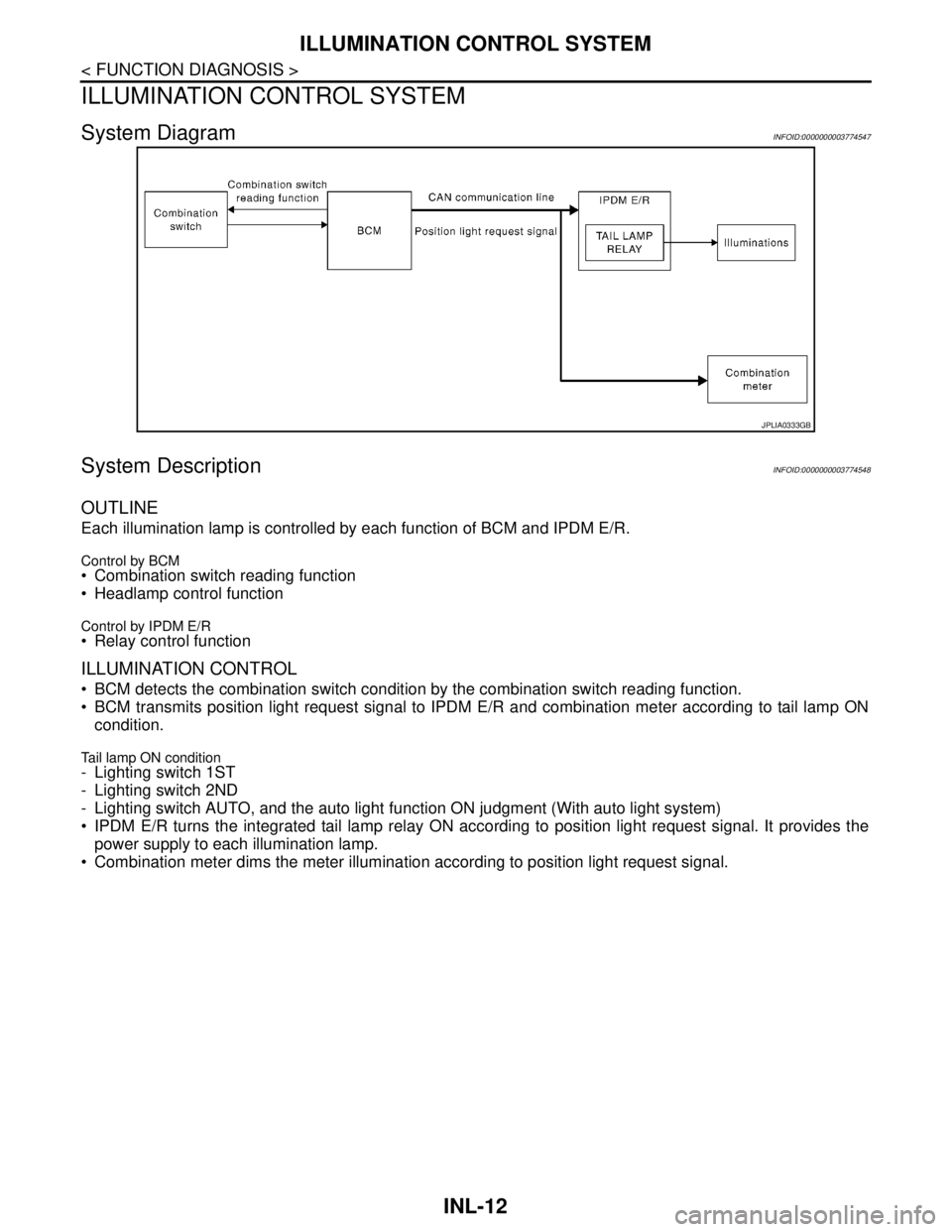
System DiagramINFOID:0000000003774547
System DescriptionINFOID:0000000003774548
OUTLINE
Each illumination lamp is controlled by each function of BCM and IPDM E/R.
Control by BCM Combination switch reading function
Headlamp control function
Control by IPDM E/R Relay control function
ILLUMINATION CONTROL
BCM detects the combination switch condition by the combination switch reading function.
BCM transmits position light request signal to IPDM E/R and combination meter according to tail lamp ON
condition.
Tail lamp ON condition- Lighting switch 1ST
- Lighting switch 2ND
- Lighting switch AUTO, and the auto light function ON judgment (With auto light system)
IPDM E/R turns the integrated tail lamp relay ON according to position light request signal. It provides the
power supply to each illumination lamp.
Combination meter dims the meter illumination according to position light request signal.
JPLIA0333GB
Page 3077 of 5121
![NISSAN TEANA 2008 Service Manual LAN-10
< FUNCTION DIAGNOSIS >[CAN FUNDAMENTAL]
TROUBLE DIAGNOSIS
Example: Main Line Between Data Link Connector and ABS Actuator and Electric Unit (Control Unit) Open Circuit
Example: CAN-H, CAN-L Har NISSAN TEANA 2008 Service Manual LAN-10
< FUNCTION DIAGNOSIS >[CAN FUNDAMENTAL]
TROUBLE DIAGNOSIS
Example: Main Line Between Data Link Connector and ABS Actuator and Electric Unit (Control Unit) Open Circuit
Example: CAN-H, CAN-L Har](/manual-img/5/57391/w960_57391-3076.png)
LAN-10
< FUNCTION DIAGNOSIS >[CAN FUNDAMENTAL]
TROUBLE DIAGNOSIS
Example: Main Line Between Data Link Connector and ABS Actuator and Electric Unit (Control Unit) Open Circuit
Example: CAN-H, CAN-L Harness Short Circuit
SKIB8740E
Unit name Symptom
ECM Engine torque limiting is affected, and shift harshness increases.
BCM Reverse warning chime does not sound.
The front wiper moves under continuous operation mode even though the front wip-
er switch being in the intermittent position.
EPS control unit The steering effort increases.
Combination meter The shift position indicator and OD OFF indicator turn OFF.
The speedometer is inoperative.
The odo/trip meter stops.
ABS actuator and electric unit (control unit) Normal operation.
TCM No impact on operation.
IPDM E/RWhen the ignition switch is ON,
The headlamps (Lo) turn ON.
The cooling fan continues to rotate.
SKIB8741E
Page 3078 of 5121
![NISSAN TEANA 2008 Service Manual LAN
TROUBLE DIAGNOSIS
LAN-11
< FUNCTION DIAGNOSIS >[CAN FUNDAMENTAL]
C
D
E
F
G
H
I
J
K
L B A
O
P N
CAN Diagnosis with CONSULT-IIIINFOID:0000000003767672
CAN diagnosis on CONSULT-III extracts the root NISSAN TEANA 2008 Service Manual LAN
TROUBLE DIAGNOSIS
LAN-11
< FUNCTION DIAGNOSIS >[CAN FUNDAMENTAL]
C
D
E
F
G
H
I
J
K
L B A
O
P N
CAN Diagnosis with CONSULT-IIIINFOID:0000000003767672
CAN diagnosis on CONSULT-III extracts the root](/manual-img/5/57391/w960_57391-3077.png)
LAN
TROUBLE DIAGNOSIS
LAN-11
< FUNCTION DIAGNOSIS >[CAN FUNDAMENTAL]
C
D
E
F
G
H
I
J
K
L B A
O
P N
CAN Diagnosis with CONSULT-IIIINFOID:0000000003767672
CAN diagnosis on CONSULT-III extracts the root cause by receiving the following information.
Response to the system call
Control unit diagnosis information
Self-diagnosis
CAN diagnostic support monitor
Self-DiagnosisINFOID:0000000003767673
CAN Diagnostic Support MonitorINFOID:0000000003767674
MONITOR ITEM (CONSULT-III)
Unit name Symptom
ECM Engine torque limiting is affected, and shift harshness increases.
Engine speed drops.
BCM Reverse warning chime does not sound.
The front wiper moves under continuous operation mode even though the front
wiper switch being in the intermittent position.
The room lamp does not turn ON.
The engine does not start (if an error or malfunction occurs while turning the igni-
tion switch OFF.)
The steering lock does not release (if an error or malfunction occurs while turning
the ignition switch OFF.)
EPS control unit The steering effort increases.
Combination meter The tachometer and the speedometer do not move.
Warning lamps turn ON.
Indicator lamps do not turn ON.
ABS actuator and electric unit (control unit) Normal operation.
TCM No impact on operation.
IPDM E/RWhen the ignition switch is ON,
The headlamps (Lo) turn ON.
The cooling fan continues to rotate.
DTCSelf-diagnosis item
(CONSULT-III indication)DTC detection condition Inspection/Action
U1000 CAN COMM CIRCUITWhen ECM is not transmitting or receiving CAN
communication signal of OBD (emission-related
diagnosis) for 2 seconds or more.
Start the inspection. Re-
fer to the applicable sec-
tion of the indicated
control unit. When a control unit (except for ECM) is not
transmitting or receiving CAN communication
signal for 2 seconds or more.
U1001 CAN COMM CIRCUITWhen ECM is not transmitting or receiving CAN
communication signal other than OBD (emis-
sion-related diagnosis) for 2 seconds or more.
U1002 SYSTEM COMMWhen a control unit is not transmitting or receiv-
ing CAN communication signal for 2 seconds or
less.
U1010 CONTROL UNIT [CAN]
When an error is detected during the initial diag-
nosis for CAN controller of each control unit.Replace the control unit
indicating “U1010” or
“P0607”. P0607 ECM
Page 3090 of 5121
![NISSAN TEANA 2008 Service Manual LAN
CAN COMMUNICATION SYSTEM
LAN-23
< FUNCTION DIAGNOSIS >[CAN]
C
D
E
F
G
H
I
J
K
L B A
O
P N
NOTE:
Refer to LAN-19, "
Abbreviation List" for the abbreviations of the connecting units.
T: Transmit R: NISSAN TEANA 2008 Service Manual LAN
CAN COMMUNICATION SYSTEM
LAN-23
< FUNCTION DIAGNOSIS >[CAN]
C
D
E
F
G
H
I
J
K
L B A
O
P N
NOTE:
Refer to LAN-19, "
Abbreviation List" for the abbreviations of the connecting units.
T: Transmit R:](/manual-img/5/57391/w960_57391-3089.png)
LAN
CAN COMMUNICATION SYSTEM
LAN-23
< FUNCTION DIAGNOSIS >[CAN]
C
D
E
F
G
H
I
J
K
L B A
O
P N
NOTE:
Refer to LAN-19, "
Abbreviation List" for the abbreviations of the connecting units.
T: Transmit R: Receive
Signal name/Connecting unitECM
ADP
AV
HVAC
M&A
STRG
BCM
ABS
TCM
IPDM-E
A/C compressor request signal TR
Accelerator pedal position signal T R R
ASCD CRUISE indicator signal T R
ASCD operation signal T R
ASCD SET indicator signal T R
Closed throttle position signal T R
Cooling fan speed request signal TR
Engine and CVT integrated control signalTR
RT
Engine coolant temperature signal T R
Engine speed signal T R R R
Engine status signal T R R
Fuel consumption monitor signal T R
Malfunctioning indicator lamp signal T R
Power generation command value signal TR
System setting signalTR
RT R
RT
Rear window defogger switch signal T R
A/C switch signal R T T
Blower fan motor switch signal R T T
Distance to empty signal R T
Fuel level low warning signal R T
Sleep-ready signalTR
RT
Sport mode switch signal T R
Vehicle speed signalRR T R RR
RR R R T
Wake up signal T R
Steering angle sensor signal T R
Buzzer output signal R T
Door switch signal R R R T R
Door unlock signal R T
Front fog light request signal R T R
Front wiper request signalTR
Headlamp washer request signal T R
High beam request signal R T R
Hood switch signalTR
Horn reminder signalTR
Ignition switch ON signalTR
RT
Page 3189 of 5121

MA-1
MAINTENANCE
C
DE
F
G H
I
J
K L
M B
MA
SECTION MA
N
O A
CONTENTS
MAINTENANCE
PREPARATION .............
...............................3
PREPARATION .............................................. .....3
Special Service Tool ........................................... ......3
Commercial Service Tool ..........................................3
Pre-Delivery Inspection Item .....................................3
ON-VEHICLE MAINTENANCE .....................5
GENERAL MAINTENANCE ........................... .....5
General Maintenance .......................................... ......5
PERIODIC MAINTENANCE ................................6
Periodic Maintenance .......................................... ......6
RECOMMENDED FLUIDS AND LUBRI-
CANTS ................................................................
11
Fluids and Lubricants .......................................... ....11
SAE Viscosity Number ............................................11
Engine Coolant Mixture Ratio .................................12
ENGINE MAINTENANCE ...................................13
DRIVE BELT .......................................................... ....13
DRIVE BELT : Exploded View ................................13
DRIVE BELT : Checking .........................................13
DRIVE BELT : Tension Adjustment ........................13
ENGINE COOLANT ............................................... ....13
ENGINE COOLANT : Inspection .............................13
ENGINE COOLANT : Draining ................................14
ENGINE COOLANT : Refilling ................................14
ENGINE COOLANT : Flushing ...............................16
RADIATOR CAP .................................................... ....16
RADIATOR CAP : Inspection ..................................17
RADIATOR ............................................................ ....17
RADIATOR : Inspection ..........................................17
FUEL LINES .......................................................... ....17
FUEL LINES : Inspection ........................................18
AIR CLEANER FILTER ......................................... ....18
AIR CLEANER FILTER : Removal and Installation
....
18
ENGINE OIL ........................................................... ....18
ENGINE OIL : Draining ............................................18
ENGINE OIL : Refilling ............................................19
OIL FILTER ............................................................ ....19
OIL FILTER : Removal and Installation ...................19
OIL FILTER : Inspection ..........................................20
SPARK PLUG ........................................................ ....20
SPARK PLUG : Removal and Installation ...............20
SPARK PLUG : Inspection ......................................21
POSITIVE CRANKCASE VENTILATION SYSTEM ....21
POSITIVE CRANKCASE VENTILATION SYS-
TEM : Inspection ......................................................
21
EVAP VAPOR LINES ............................................ ....22
EVAP VAPOR LINES : Inspection ...........................22
CHASSIS MAINTENANCE ...............................23
HEADLAMP AIMING ADJUSTMENT (XENON
TYPE) .......... ................................. ..............................
23
HEADLAMP AIMING ADJUSTMENT (XENON
TYPE) : Description ............................................. ....
23
HEADLAMP AIMING ADJUSTMENT (XENON
TYPE) : Aiming Adjustment Procedure (Low
Beam) ......................................................................
24
HEADLAMP AIMING ADJUSTMENT (XENON
TYPE) : Aiming Adjustment Procedure (High
Beam) ......................................................................
25
HEADLAMP AIMING ADJUSTMENT (HALOGEN
TYPE) ........................................... ..............................
27
HEADLAMP AIMING ADJUSTMENT (HALOGEN
TYPE) : Description ............................................. ....
27
HEADLAMP AIMING ADJUSTMENT (HALOGEN
TYPE) : Aiming Adjustment Procedure (Low
Beam) ......................................................................
29
Page 3190 of 5121

MA-2
HEADLAMP AIMING ADJUSTMENT (HALOGEN
TYPE) : Aiming Adjustment Procedure (High
Beam) .....................................................................
30
EXHAUST SYSTEM ..................................................31
EXHAUST SYSTEM : Inspection ...........................32
CVT FLUID: RE0F10A ..............................................32
CVT FLUID: RE0F10A : Inspection ........................32
CVT FLUID: RE0F10A : Changing .........................33
CVT FLUID: RE0F09B ..............................................34
CVT FLUID: RE0F09B : Inspection ........................34
CVT FLUID: RE0F09B : Changing .........................35
WHEELS (BONDING WEIGHT TYPE) .....................35
WHEELS (BONDING WEIGHT TYPE) : Adjust-
ment ........................................................................
35
BRAKE FLUID LEVEL AND LEAKS ........................37
BRAKE FLUID LEVEL AND LEAKS : Inspection ...37
BRAKE LINES AND CABLES ..................................37
BRAKE LINES AND CABLES : Inspection .............38
BRAKE FLUID ..........................................................38
BRAKE FLUID : Changing ......................................38
DISC BRAKE ............................................................38
DISC BRAKE : Inspection ......................................38
DISC BRAKE : Front Disc Brake ............................39
DISC BRAKE : Rear Disc Brake .............................39
STEERING GEAR AND LINKAGE ...........................39
STEERING GEAR AND LINKAGE : Inspection ......39
POWER STEERING FLUID AND LINES ..................39
POWER STEERING FLUID AND LINES : Inspec-
tion ..........................................................................
40
AXLE AND SUSPENSION PARTS ...........................40
AXLE AND SUSPENSION PARTS : Inspection .....40
DRIVE SHAFT ...........................................................40
DRIVE SHAFT : Inspection .....................................41
BODY MAINTENANCE .....................................42
LOCKS, HINGES AND HOOD LATCH .....................42
LOCKS, HINGES AND HOOD LATCH : Lubricat-
ing ...........................................................................
42
SEAT BELT, BUCKLES, RETRACTORS, AN-
CHORS AND ADJUSTERS ......................................
42
SEAT BELT, BUCKLES, RETRACTORS, AN-
CHORS AND ADJUSTERS : Inspection .................
42
BODY CORROSION .................................................42
BODY CORROSION : Checking Body Corrosion ...42
SERVICE DATA AND SPECIFICATIONS
(SDS) ..........................................................
44
SERVICE DATA AND SPECIFICATIONS
(SDS) .................................................................
44
DRIVE BELTS ...........................................................44
DRIVE BELTS : Drive Belt ......................................44
ENGINE COOLANT ..................................................44
ENGINE COOLANT : Periodical Maintenance
Specification ............................................................
44
ENGINE OIL ..............................................................44
ENGINE OIL :
Periodical Maintenance Specification ....................
44
SPARK PLUG ...........................................................44
SPARK PLUG : Spark Plug ....................................44
ROAD WHEEL ..........................................................44
ROAD WHEEL : Road Wheel .................................44
Page 3193 of 5121

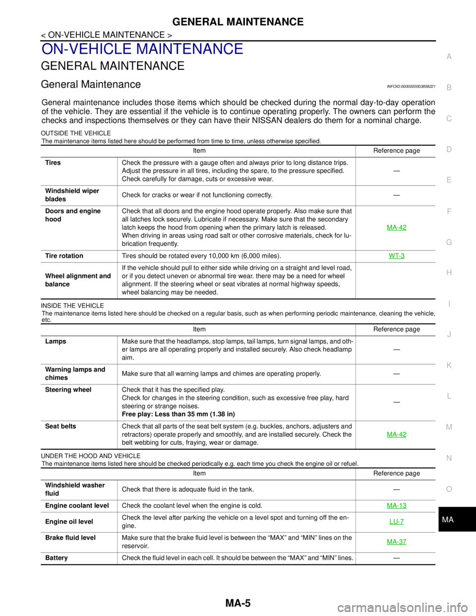
GENERAL MAINTENANCE
MA-5
< ON-VEHICLE MAINTENANCE >
C
D
E
F
G
H
I
J
K
L
MB
MAN
OA
ON-VEHICLE MAINTENANCE
GENERAL MAINTENANCE
General MaintenanceINFOID:0000000003858221
General maintenance includes those items which should be checked during the normal day-to-day operation
of the vehicle. They are essential if the vehicle is to continue operating properly. The owners can perform the
checks and inspections themselves or they can have their NISSAN dealers do them for a nominal charge.
OUTSIDE THE VEHICLE
The maintenance items listed here should be performed from time to time, unless otherwise specified.
INSIDE THE VEHICLE
The maintenance items listed here should be checked on a regular basis, such as when performing periodic maintenance, cleaning the vehicle,
etc.
UNDER THE HOOD AND VEHICLE
The maintenance items listed here should be checked periodically e.g. each time you check the engine oil or refuel.
Item Reference page
TiresCheck the pressure with a gauge often and always prior to long distance trips.
Adjust the pressure in all tires, including the spare, to the pressure specified.
Check carefully for damage, cuts or excessive wear.—
Windshield wiper
bladesCheck for cracks or wear if not functioning correctly. —
Doors and engine
hoodCheck that all doors and the engine hood operate properly. Also make sure that
all latches lock securely. Lubricate if necessary. Make sure that the secondary
latch keeps the hood from opening when the primary latch is released.
When driving in areas using road salt or other corrosive materials, check for lu-
brication frequently.MA-42
Tire rotationTires should be rotated every 10,000 km (6,000 miles).WT-3
Wheel alignment and
balanceIf the vehicle should pull to either side while driving on a straight and level road,
or if you detect uneven or abnormal tire wear. there may be a need for wheel
alignment. If the steering wheel or seat vibrates at normal highway speeds,
wheel balancing may be needed.
Item Reference page
LampsMake sure that the headlamps, stop lamps, tail lamps, turn signal lamps, and oth-
er lamps are all operating properly and installed securely. Also check headlamp
aim.—
Warning lamps and
chimesMake sure that all warning lamps and chimes are operating properly. —
Steering wheelCheck that it has the specified play.
Check for changes in the steering condition, such as excessive free play, hard
steering or strange noises.
Free play: Less than 35 mm (1.38 in)—
Seat beltsCheck that all parts of the seat belt system (e.g. buckles, anchors, adjusters and
retractors) operate properly and smoothly, and are installed securely. Check the
belt webbing for cuts, fraying, wear or damage.MA-42
Item Reference page
Windshield washer
fluidCheck that there is adequate fluid in the tank. —
Engine coolant levelCheck the coolant level when the engine is cold.MA-13
Engine oil levelCheck the level after parking the vehicle on a level spot and turning off the en-
gine.LU-7
Brake fluid levelMake sure that the brake fluid level is between the “MAX” and “MIN” lines on the
reservoir.MA-37
BatteryCheck the fluid level in each cell. It should be between the “MAX” and “MIN” lines. —